Bonetti - Measurement Resources
Bonetti - Measurement Resources
Bonetti - Measurement Resources
- No tags were found...

Create successful ePaper yourself
Turn your PDF publications into a flip-book with our unique Google optimized e-Paper software.
BONT ® Glass Level GaugesTypes, Material Schedules, ApplicationsIn this Bulletin we give the description of our level gauges madeof metallic materials and omit that ones of non-metallic materials(Ebonite, Polypropylene, PTFE, etc.): information on request.Max operating conditionsRating ▲Fig.MaterialType Page Press. Temp. ASME PN864 Schedulebar °C Class barFluidBR14 - GP11 6BR 14 - G11 652 20 211 25 Water steam, other fluidsBR12 - GP11 7 52 32 236 40 Water steamBR12 - G11 7 52, 6464 12040 300Other fluids (Remark 14)BR22 - GP11 8 52 12 187 16 Water steamBR22 - GP12 8 52, 6428 3810 300Other fluids (Remark 14)BR23 - GP11 9 52 22 216 Water steamBR23 - GP12 9 52, 63, 64105 3880 300600 100 Other fluids (Remark 14)BR24 - GP11 10 52 32 236 Water steamBR24 - GP12 10 52, 63, 64165 38105 300900 100 Other fluids (Remark 14)BR28 - G41 1151, 52 200 38 Any fluids, water steam1500 25063, 64 160 300 excepted (Remark 14)BR28 - GP12 11 52, 63, 64165 38 Any fluids, water steam105 300 excepted (Remark 14)BR25 - GP12 12 52, 63, 64105 38 Any fluids, water steam900 10062 300 excepted (Remark 14))BR13 - G51 13 52 400 120 (2500) (400) Any fluids (Remark 9)BR26 & BR27 1452, 55, 61 Any fluids, water steam(600)62, 63, 64 } excepted (Remark 10)52 6 158 Water steam (Remark 11)BTV - GP11 1552, 63, 64 12 38 Not dangerous fluidsBT23 - GP11 16 52 12 187 Water steam (Remark 12)BT23 - GP12 16 52, 63, 6451 3830 300300 Other fluids (Remark 14)BT24 - GP11 17 52 20 211 Water steam (Remark 12)BT24 - GP12 17 52, 63, 64105 3862 300600 100 Other fluids (Remark 14)BT25 - GP12 18 52, 63, 64105 38 Any fluids, water steam600 10062 300 excepted (Remark 14)BT28 - GP11 19 52 50 264 Water steam (Remark 12)BT28 - GP12 19 52, 63, 64120 3880 300600 100 Other fluids (Remark 14)BT29 - G41 20 52, 63, 64165 38 Any fluids, water steam900 160100 300 excepted (Remark 14)BT33 - G52 22 51 90 302 Water steamBT32 - G52 23 51 103 313 Water steamBT26 & BT27 2652, 55, 61 Any fluids, water steam(600)62, 63, 64 } excepted (Remark 10)BC24 - GP11 24 52 20 211 Water steamBC28 - GP11 24 52 40 249See alsotable atWater steamBC33 - G52 24 52 90 302 page 24Water steamBC32 - G52 24 51 103 313 Water steamBC1 - G55 25 51 210 368 Water steamNOTE: Maximum allowable temperature according to DIN 7081 / 1999-05.For operating condition with temperature over 300 °C, please apply to our Sales or Technical department.▲ The shown rating is an indication only: level gauge rating can change according the level gauge valve fitted on it.See also notes on page 5 and apply to us for further informationBICOLOUR TRANSPARENT REFLEX4BONT
Reflex BONT ® Level Gaugestype BR14 with GP11 and G11 valvesFig. 836.1Type BR14-GP11Size Length length Visible CC min CC min. Weightof glass of body length with GP11 with G11G B V G kg3 165 178 145 291 279 9,04 190 203 170 316 304 9,45 220 233 200 346 334 9,86 250 263 230 376 364 10,37 280 293 260 406 394 10,88 320 333 300 446 434 11,39 340 353 320 466 454 11,71 Connections between gauge and valves are made by end tubesand stuffing boxes.2 According to the position of the shut-off valves compared withthe gauge body, the level gauge is named “right-handed” or“left-handed”. Fig. 836.1 shows a left-handed gauge.Each level gauge can be assembled right-handed or left-handed.Usually two level gauges (1 right and 1 left) are installed onsteam vessels.3 According to some Steam Boiler Regulations, the visiblelength of the level gauges installed on steam boilers must benot shorter than a fixed length. Therefore the suitability ofthe smaller sizes must be checked.4 When ordering a level gauge please state:– Centre to centre distance between connections (CC)– Standard, Size and Finishing of connections– Whether right-handed or left-handed.5 Flanges are finished to customer prescriptions. Please state:– Standard – Size– Pressure class – FinishingThe inside passage through the gauge is 10 mm.6 Instead of flanges, connections can be delivered with threadedends. Standard is 3/4” NPT, union. Other Standard and sizeon request.7 BR14 gauges are fitted with reflex glasses type A (see page 38).8 Operating conditions and material schedules on pages 4 and 5.9 Applicable optionals and bolting torques on pages 27, 36, 37.6BONT
Reflex BONT ® Level Gaugestype BR12 with GP11, GP12, G11 and G12 valvesFig. 837Type BR12-GP11Size length length Visible CC min. CC min. CC min. CC min. Weightof glass of body length with with with withG B V GP11 GP12 G11 G12 kg1 115 128 95 241 209 229 178 11,72 140 153 120 266 234 254 203 12,13 165 178 145 291 259 279 228 12,94 190 203 170 316 284 304 253 13,35 220 233 200 346 314 334 283 14,16 250 263 230 376 344 364 313 157 280 293 260 406 374 394 343 15,58 320 333 300 446 414 434 383 16,59 340 353 320 466 434 454 403 17,22x4 190 413 380 526 494 514 463 18,22x5 220 473 440 586 554 574 523 19,82x6 250 533 500 646 614 634 583 21,72x7 280 593 560 706 674 694 643 22,62x8 320 673 640 786 754 774 723 24,62x9 340 713 680 826 794 814 763 263x6 250 803 770 916 884 904 853 28,43x7 280 893 860 1006 974 994 943 29,83x8 320 1013 980 1126 1094 1114 1063 32,83x9 340 1073 1040 1186 1154 1174 1123 34,94x7 280 1193 1160 1306 1274 1294 1243 36,94x8 320 1353 1320 1466 1434 1454 1403 40,94x9 340 1433 1400 1546 1514 1534 1483 43,75x7 280 1493 1460 1606 1574 1594 1543 44,35x8 320 1693 1660 1806 1774 1794 1743 49,15x9 340 1793 1760 1906 1874 1894 1843 52,66x8 320 2033 2000 2146 2114 2134 2083 57,26x9 340 2153 2120 2266 2234 2254 2203 61,47x9 340 2513 2480 2626 2594 2614 2563 70,301 Connections between gauge and valves are made:- for BR12 with GP11 or G11, by end tubes and stuffing boxes- for BR12 with GP12 or G12, by NPT screwed nipples.02 According to the position of the shut-off valves compared withthe gauge body, the level gauge is named “right-handed” or“left-handed”. Fig. 837 shows a left-handed gauge.Each level gauge can be assembled right-handed or left-handed.Usually two level gauges (1 right and 1 left) are installed onsteam vessels.03 According to some Steam Boiler Regulations, the visiblelength of the level gauges installed on steam boilers must benot shorter than a fixed length. Therefore the suitability ofthe smaller sizes must be checked.04 When ordering a level gauge please state:– Centre to centre distance between connections (CC)– Standard, Size and Finishing of connections– Whether right-handed or left-handed.05 Flanges are finished to customer prescriptions. Please state:– Standard – Size– Pressure class – FinishingThe inside passage through the gauge is 10 mm.060Instead of flanges, connections can be delivered with threadedends. Standard is 3/4” NPT, union. Other Standard and sizeon request.07 BR12 gauges are fitted with reflex glasses type A (see page 38).08 Operating conditions and material schedules on pages 4 and 5.09 Applicable optionals and bolting torques on pages 27, 36, 37.10 Gauge bodies without valves can be supplied:– end connected (threaded or flanged)– side connected (threaded or flanged)– back connected (threaded or flanged).Please state connecting dimensions and Standard.BONT7
Reflex BONT ® Level Gaugestype BR22 with GP11, GP12, G41/42 and GS41/42 valvesFig. 838.1Type BR22-GP11Size length length Visible CC minimum Weight CC min. Weightof glass of body length G & GSG B V GP11 GP12 kg 41 & 42 kg1 115 128 95 241 209 10,0 218 15,02 140 153 120 266 234 10,3 243 15,73 165 178 145 291 259 10,8 268 16,24 190 203 170 316 284 11,1 293 16,55 220 233 200 346 314 11,3 323 16,76 250 263 230 376 344 12,0 353 17,47 280 293 260 406 374 12,2 383 17,68 320 333 300 446 414 12,8 423 18,29 340 353 320 466 434 13,0 443 18,42x4 190 413 380 526 494 13,9 503 19,32x5 220 473 440 586 554 14,4 563 19,82x6 250 533 500 646 614 15,7 623 21,12x7 280 593 560 706 674 16,1 683 21,52x8 320 673 640 786 754 17,4 763 22,82x9 340 713 680 826 794 17,8 803 23,23x6 250 803 770 916 884 19,4 893 24,83x7 280 893 860 1006 974 20,0 983 25,43x8 320 1013 980 1126 1094 21,9 1103 27,33x9 340 1073 1040 1186 1154 22,5 1163 27,94x7 280 1193 1160 1306 1274 23,9 1283 29,34x8 320 1353 1320 1466 1434 26,5 1443 31,94x9 340 1433 1400 1546 1514 27,3 1523 32,75x7 280 1493 1460 1606 1574 27,8 1583 33,25x8 320 1693 1660 1806 1774 31,0 1783 36,45x9 340 1793 1760 1906 1874 32,0 1883 37,46x8 320 2033 2000 2146 2114 35,6 2123 41,06x9 340 2153 2120 2266 2234 36,8 2243 42,27x9 340 2513 2480 2626 2594 41,5 2603 46,901 Connections between gauge and valves are made–for BR22-GP11, by end tubes and stuffing boxes–for BR22-GP12, by NPT screwed nipples–for BR22-G41/42 & GS41/42, by NPT screwed nipples.Minimum CC distance, shown on table is referred to 1/2”NPT connections.On request 3/4” NPT connection can be supplied.02 According to the position of the shut-off valves compared withthe gauge body, the level gauge is named “right-handed” or“left-handed”. Fig. 838.1 shows a left-handed gauge.Each level gauge can be assembled right-handed or left-handed.Usually two level gauges (1 right and 1 left) are installed onsteam vessels.03 According to some Steam Boiler Regulations, the visiblelength of the level gauges installed on steam boilers must benot shorter than a fixed length. Therefore the suitability ofthe smaller sizes must be checked.04 When ordering a level gauge please state:– Centre to centre distance between connections (CC)– Standard, Size and Finishing of connections– Whether right-handed or left-handed.05 Flanges are finished to customer prescriptions. Please state:– Standard – Size– Pressure class – FinishingThe inside passage through the gauge is 10 mm.060Instead of flanges, connections can be delivered with threadedends. Standard is 3/4” NPT, union. Other Standard and sizeon request.07 BR22 gauges are fitted with reflex glasses type B (see page 38).08 Operating conditions and material schedules on pages 4 and 5.Graph below shows rating for size 9 and smaller, combinedincluded.09 Applicable optionals and bolting torques on pages 27, 36, 37..10 Gauge bodies without valves can be supplied:– end connected (threaded or flanged)– side connected (threaded or flanged)– back connected (threaded or flanged).Please state connecting dimensions and Standard.11 For level gauges type BR22-G41, BR22-G42, BR22-GS41,BR22-GS42, see page 30-31.8BONT
Reflex BONT ® Level Gaugestype BR23 with GP11, GP12, G41/42 and GS41/42 valvesFig. 839.1Type BR23-GP11Size length length Visible CC minimum Weight CC min. Weightof glass of body length G & GSG B V GP11 GP12 kg 41 & 42 kg1 115 128 95 241 209 10,4 218 15,82 140 153 120 266 234 10,8 243 16,23 165 178 145 291 259 11,7 268 17,14 190 203 170 316 284 12,2 293 17,65 220 233 200 346 314 13,0 323 18,46 250 263 230 376 344 13,9 353 19,37 280 293 260 406 374 14,2 383 19,68 320 333 300 446 414 15,2 423 20,69 340 353 320 466 434 15,7 443 21,12x4 190 413 380 526 494 18,0 503 23,42x5 220 473 440 586 554 19,5 563 24,92x6 250 533 500 646 614 21,4 623 26,82x7 280 593 560 706 674 22,0 683 27,42x8 320 673 640 786 754 23,9 763 29,32x9 340 713 680 826 794 24,9 803 30,33x6 250 803 770 916 884 28,9 893 34,33x7 280 893 860 1006 974 29,7 983 35,13x8 320 1013 980 1126 1094 32,7 1103 38,13x9 340 1073 1040 1186 1154 34,2 1163 39,64x7 280 1193 1160 1306 1274 37,5 1283 42,94x8 320 1353 1320 1466 1434 41,5 1443 46,94x9 340 1433 1400 1546 1514 43,5 1523 48,95x7 280 1493 1460 1606 1574 45,3 1583 50,75x8 320 1693 1660 1806 1774 50,2 1783 55,65x9 340 1793 1760 1906 1874 52,8 1883 58,26x8 320 2033 2000 2146 2114 58,1 2123 63,56x9 340 2153 2120 2266 2234 62,0 2243 67,47x9 340 2513 2480 2626 2594 71,3 2603 76,701 Connections between gauge and valves are made–for BR23-GP11, by end tubes and stuffing boxes–for BR23-GP12, by NPT screwed nipples–for BR23-G41/42 & GS41/42, by NPT screwed nipples.Minimum CC distance, shown on table is referred to 1/2”NPT connections.On request 3/4” NPT connection can be supplied.02 According to the position of the shut-off valves compared withthe gauge body, the level gauge is named “right-handed” or“left-handed”. Fig. 839.1 shows a left-handed gauge.Each level gauge can be assembled right-handed or left-handed.Usually two level gauges (1 right and 1 left) are installed onsteam vessels.03 According to some Steam Boiler Regulations, the visiblelength of the level gauges installed on steam boilers must benot shorter than a fixed length. Therefore the suitability ofthe smaller sizes must be checked.04 When ordering a level gauge please state:– Centre to centre distance between connections (CC)– Standard, Size and Finishing of connections– Whether right-handed or left-handed.05 Flanges are finished to customer prescriptions. Please state:– Standard – Size– Pressure class – FinishingThe inside passage through the gauge is 10 mm.060Instead of flanges, connections can be delivered with threadedends. Standard is 3/4” NPT, union. Other Standard and sizeon request.07 BR23 gauges are fitted with reflex glasses type B (see page 38).08 Operating conditions and material schedules on pages 4 and 5.Graph below shows rating for size 9 and smaller, combinedincluded.09 Applicable optionals and bolting torques on pages 27, 36, 37.10 Gauge bodies without valves can be supplied:– end connected (threaded or flanged)– side connected (threaded or flanged)– back connected (threaded or flanged).Please state connecting dimensions and Standard.11 For level gauges type BR23-G41, BR23-G42, BR23-GS41,BR23-GS42, see page 30-31.BONT9
Reflex BONT ® Level GaugesType BR24 with GP11, GP12, G41/42 and GS41/42 valvesFig. 840.1Type BR24-GP11Size length length Visible CC minimum Weight CC min. Weightof glass of body length G & GSG B V GP11 GP12 kg 41 & 42 kg1 115 128 95 241 209 11,3 218 16,72 140 153 120 266 234 11,8 243 17,23 165 178 145 291 259 12,8 268 18,24 190 203 170 316 284 13,3 293 18,75 220 233 200 346 314 14,3 323 19,76 250 263 230 376 344 15,3 353 20,77 280 293 260 406 374 15,8 383 21,28 320 333 300 446 414 16,9 423 22,39 340 353 320 466 434 17,7 443 23,12x4 190 413 380 526 494 19,2 503 24,62x5 220 473 440 586 554 21,3 563 26,72x6 250 533 500 646 614 23,1 623 28,52x7 280 593 560 706 674 24,4 683 29,82x8 320 673 640 786 754 26,3 763 31,72x9 340 713 680 826 794 27,9 803 33,33x6 250 803 770 916 884 31,0 893 36,43x7 280 893 860 1006 974 33,0 983 38,43x8 320 1013 980 1126 1094 35,7 1103 41,13x9 340 1073 1040 1186 1154 38,1 1163 43,54x7 280 1193 1160 1306 1274 41,7 1283 47,14x8 320 1353 1320 1466 1434 45,1 1443 50,54x9 340 1433 1400 1546 1514 48,2 1523 53,65x7 280 1493 1460 1606 1574 50,3 1583 55,75x8 320 1693 1660 1806 1774 54,6 1783 60,05x9 340 1793 1760 1906 1874 58,4 1883 63,86x8 320 2033 2000 2146 2114 64,0 2123 69,46x9 340 2153 2120 2266 2234 68,6 2243 74,07x9 340 2513 2480 2626 2594 78,7 2603 84,101 Connections between gauge and valves are made–for BR24-GP11, by end tubes and stuffing boxes–for BR24-GP12, by NPT screwed nipples–for BR24-G41/42 & GS41/42, by NPT screwed nipples.Minimum CC distance, shown on table is referred to 1/2”NPT connections.On request 3/4” NPT connection can be supplied.02 According to the position of the shut-off valves compared withthe gauge body, the level gauge is named “right-handed” or“left-handed”. Fig. 840.1 shows a left-handed gauge.Each level gauge can be assembled right-handed or left-handed.Usually two level gauges (1 right and 1 left) are installed onsteam vessels.03 According to some Steam Boiler Regulations, the visiblelength of the level gauges installed on steam boilers must benot shorter than a fixed length. Therefore the suitability ofthe smaller sizes must be checked.04 When ordering a level gauge please state:– Centre to centre distance between connections (CC)– Standard, Size and Finishing of connections– Whether right-handed or left-handed.05 Flanges are finished to customer prescriptions. Please state:– Standard – Size– Pressure class – FinishingThe inside passage through the gauge is 10 mm.060Instead of flanges, connections can be delivered with threadedends. Standard is 3/4” NPT, union. Other Standard and sizeon request.07 BR24 gauges are fitted with reflex glasses type B (see page 38).08 Operating conditions and material schedules on pages 4 and 5.Graph below shows rating for size 9 and smaller, combinedincluded.09 Applicable optionals and bolting torques on pages 27, 36, 37.10 Gauge bodies without valves can be supplied:– end connected (threaded or flanged)– side connected (threaded or flanged)– back connected (threaded or flanged).Please state connecting dimensions and Standard.11 For level gauges type BR24-G41, BR24-G42, BR24-GS41,BR24-GS42, see page 30-31.10BONT
Reflex BONT ® Level Gaugestype BR28 with GP12, G41/42 and GS41/42 valvesFig. 856Type BR28-G41Size length length Visible CC min. Weight CC min. Weightof glass of body length with G & GSG B V GP12 kg 41 & 42 kg1 115 165 95 246 18,8 255 24,22 140 190 120 271 19,6 280 25,03 165 215 145 296 20,5 305 25,94 190 240 170 321 21,5 330 26,95 220 270 200 351 22,7 360 28,16 250 300 230 381 24,1 390 29,57 280 330 260 411 25,4 420 30,88 320 370 300 451 26,8 460 32,29 340 390 320 471 27,7 480 33,12x4 190 450 380 531 38,9 540 44,32x5 220 510 440 591 41,3 600 46,72x6 250 570 500 651 44,1 660 49,52x7 280 630 560 711 46,7 720 52,12x8 320 710 640 791 49,5 800 54,92x9 340 750 680 831 51,3 840 56,73x6 250 840 770 921 64,1 930 69,53x7 280 930 860 1011 68,0 1020 73,43x8 320 1050 980 1131 72,2 1140 77,63x9 340 1110 1040 1191 74,9 1200 80,34x7 280 1230 1160 1311 89,3 1320 94,74x8 320 1390 1320 1471 94,9 1480 100,34x9 340 1470 1400 1551 98,5 1560 103,95x7 280 1530 1460 1611 110,6 1620 116,05x8 320 1730 1660 1811 117,6 1820 123,05x9 340 1830 1760 1911 122,1 1920 127,56x8 320 2070 2000 2151 140,3 2160 145,76x9 340 2190 2120 2271 145,7 2280 151,17x9 340 2550 2480 2631 169,3 2640 174,701 Connections between gauge and valves are made–for BR28-GP11, by end tubes and stuffing boxes–for BR28-GP12, by NPT screwed nipples–for BR28-G41/42 & GS41/42, by NPT screwed nipples.Gauge/valve standard NPT connection is 1/2”.On request 3/4” NPT connection can be supplied.02 According to the right of left position of the stop valves handleof the gauge body, the level gauges are named righthandled or left-handed. Fig. 856 shows a left-handed levelgauges.03 When ordering a level gauge please state:– Centre to centre distance between connections (CC)– Standard, Size and Finishing of connections– Whether right-handed or left-handed.04 Flanges are finished to customer prescriptions. Please state:– Standard – Size– Pressure class – FinishingThe inside passage through the gauge is 12,5 mm.050Instead of flanges, connections can be delivered with threaded ends.It is standard 3/4” NPT union.06 BR28 gauges are fitted with reflex glasses type B (see page38).07 Operating conditions and material schedules on pages 4 and5. Graph below shows rating for size 9 and smaller, combined included.08 Applicable optionals and bolting torques on pages 27, 36, 37.09 Gauge bodies without valves can be supplied:– end connected (threaded or flanged)– side connected (threaded or flanged)– back connected (threaded or flanged).Please state connecting dimensions and Standard.10 For level gauges type BR28-G42, BR28-GS41, BR28-GS42,see page 30-31.BONT11
Reflex BONT ® Level Gaugestype BR25 with GP12, G41/42 and GS41/42 valvesFig. 841Type BR25-GP12Size length length Visible CC min. Weight CC min. Weightof glass of body length with G & GSG B V GP12 kg 41 & 42 kg1 115 158 95 239 14,4 248 19,82 140 183 120 264 15,5 273 20,93 165 208 145 289 16,6 298 22,04 190 233 170 314 18,6 323 24,05 220 263 200 344 19,0 353 24,46 250 293 230 374 20,3 383 25,77 280 323 260 404 22,8 413 28,28 320 363 300 444 23,3 453 28,79 340 383 320 464 24,2 473 29,62x4 190 443 380 524 26,6 533 32,02x5 220 503 440 584 29,2 593 34,62x6 250 563 500 644 31,8 653 37,22x7 280 623 560 704 34,4 713 39,82x8 320 703 640 784 37,9 793 43,32x9 340 743 680 824 39,6 833 45,03x6 250 833 770 914 43,3 923 48,73x7 280 923 860 1004 47,2 1013 52,63x8 320 1043 980 1124 52,4 1133 57,83x9 340 1103 1040 1184 55,0 1193 60,44x7 280 1223 1160 1304 60,0 1313 65,44x8 320 1383 1320 1464 66,9 1473 72,34x9 340 1463 1400 1544 70,4 1553 75,85x7 280 1523 1460 1604 72,8 1613 78,25x8 320 1723 1660 1804 81,5 1813 86,95x9 340 1823 1760 1904 85,8 1913 91,26x8 320 2063 2000 2144 96,0 2153 101,46x9 340 2183 2120 2264 101,2 2273 106,67x9 340 2543 2480 2624 116,6 2633 122,01 Type BR25-GP12 level gauge is LARGE CHAMBERED. Thegauge body is machined from a tube having thick wall andinternal Ø of about 40 mm. Large chamber level gaugesshould be used where the medium boils or surges.2 Connections between gauge and valves are made by NPTscrewed nipples.Minimum CC distance, shown on table is referred to 1/2”NPT connections.On request 3/4” NPT connection can be supplied.3 According to the position of the shut-off valves compared withthe gauge body, the level gauge is named “right-handed” or“left-handed”. Fig. 841 shows a left-handed gauge.Each level gauge can be assembled right-handed or left-handed.4 When large chamber body is required with butt-welding endcaps, length of body (B) and minimum C. to C. (CC min)have to be increased of 40 mm.5 When ordering a level gauge please state:– Centre to centre distance between connections (CC)– Standard, Size and Finishing of connections– Whether right-handed or left-handed.6 Flanges are finished to customer prescriptions. Please state:– Standard – Size– Finishing – Pressure classThe inside passage through the gauge is 40 mm.70 Instead of flanges, connections can be delivered with threadedends. Standard is 3/4” NPT, union. Other Standard and sizeon request.8 BR25 gauges are fitted with reflex glasses type B (see page 38).9 Operating conditions and material schedules on pages 4 and 5.Graph below shows rating for size 9 and smaller, combinedincluded.10 Applicable optionals and bolting torques on pages 27, 36, 37.11 Gauge bodies without valves can be supplied:– end connected (threaded or flanged)– side connected (threaded or flanged)– back connected (threaded or flanged).Please state connecting dimensions and Standard.12 For level gauges type BR25-G41, BR25-G42, BR25-GS41,BR25-GS42, see page 30-31.12BONT
Reflex BONT ® Level Gaugestype BR13 with G51 valvesFig. 857Type BR13-G511 Connections between gauge and valves are made by flanges.Gauge body cannot be rotated on its axis. Other connectionson request.2 According to the right or left position of the handwheel of thestop valves on the gauge body, the level gauges are namedright-handed or left-handed fig. 857 shows a right-handedlevel gauge.3 When ordering a level gauge please state:- Centre to centre distance between connections (CC)- Standard. Size and Finishing of connections- Whether right-handed or left-handed.4 Flanges are finished to customer prescriptions. Please state:– Standard – Size– Pressure class – FinishingThe inside passage through the gauge is at least 12,5 mm.5 Instead of flanges, connections to vessel can be delivered withthreaded ends or with weld ends.6 BR13 gauges are fitted with reflex glasses type A-BR13 (seepage 38), that ARE NOT COMPRESSED by the tighteningscrew. Joint Dimensions and Maintenance Instructions onrequest.7 Operating conditions and material schedules on pages 4 and 5.8 Applicable optionals and bolting torques on pages 27, 36, 37.9 Gauge bodies without valves can be supplied:– end connected (threaded or flanged)– side connected (threaded or flanged)– back connected (threaded or flanged).Please state connecting dimensions and Standard.Size length length Visible CC min. Weightof glass of body length lengthG B V kg3 165 481 143 331 75,04 190 506 168 356 78,05 220 536 198 386 81,06 250 566 228 416 85,07 280 596 258 446 88,08 320 636 298 486 92,09 340 656 318 506 94,02x4 190 721 383 571 106,02x5 220 794 456 644 112,02x6 250 867 529 717 120,02x7 280 897 559 747 126,02x8 320 980 642 830 134,02x9 340 1043 705 893 138,03x6 250 1168 830 1018 155,03x7 280 1198 860 1048 164,03x8 320 1324 986 1174 176,03x9 340 1430 1092 1280 182,04x7 280 1499 1161 1349 202,04x8 320 1668 1330 1518 218,04x9 340 1817 1479 1667 226,05x7 280 2012 1674 1862 260,05x8 320 2204 1866 2054 270,05x9 340 2356 2018 2206 302,06x8 320 2591 2253 2441 314,06x9 340 2700 2362 2550 344,07x9 340 2978 2640 2828 358,0BONT13
Reflex BONT ® Level GaugesWeld - on Bodies, type BR26 and BR27Fig. 717 Type BR26 Fig. 821 Type BR27Size Length. Length. Visible Weightof glass of body length BR26 BR27G B V kg kg1 115 128 95 4.8 3.62 140 153 120 5.7 4.33 165 178 145 6.6 5.04 190 203 170 7.5 5.75 220 233 200 8.6 6.66 250 263 230 9.8 7.57 280 293 260 10.9 8.38 320 333 300 12.4 9.49 340 353 320 13.1 10.01 These gauge bodies are suitable for welding directly on thevessel. Therefore, no valves can be fitted between vessel andgauge, and incase of glass breakage, the fluid flowing from thevessel cannot be stopped.2 It is necessary to control the suitability of the vessel wall, onwhich the gauge body is to be welded as this must not beexcessively weakened by the holes or communicating windowwith the gauge. Steel plates to strengthen the vessel wallshould be used whenever this is possible.3 During the welding operation, be careful to not expose thegauge body for long time to high temperatures, as this mightdamage the flatness of the glass sealing surface.5 When enquiring or ordering BR27 please state the externalradius (R) of the vessel on which the gauge must be welded.6 For visible lengths over 320 mm two or more single gaugebodies will have to be welded on the vessel. In this case it isadvisable to fit the gauge bodies not along the same verticalline, but offset.7 BR26 and BR27 are fitted with reflex glasses type B (seepage 38).8 Operating conditions and material schedules on pages 4 and 5.9 Applicable optionals and bolting torques on pages 36, 37.4 For BR26 the connecting lip is provided to facilitate the weldingoperation.14BONT
Tubular glass BONT ® Level Gaugestype BTV-GP11Fig. 842 Type BTV-GP11 Fig. 720 Fig. 721Dimensions:Max C. to C. CC max = 2000 mmGlass tube length G = CC –28 mmVisible length V = CC –110 mmWeight nearly kg 7,01 Type BTV-GP11 level gauges are equipped with a transparentglass tube of 16 mm outside diameter. The limitation of theoperating conditions is due to the glass tube, while the valvestype GP11 are suitable for higher pressure and temperature.2 As the glass tubes are usually found on sale up to a maximumstandard length of about 2000 mm, when the centre tocentre distance is longer than this size, the installation of several,cascade disposed level gauges or the application of anintermediate support with stuffing-boxes are necessary. In thelatter case the length of each glass tube will be half the centreto centre distance minus 17 mm.3 To protect the glass tube against shocks we supply on request– U shaped metallic protector (Fig. 720) to be fixed to thestuffing box gland and/or– acrylic resin tube protector (Fig. 721) sealed by O-Rings tothe stuffing box gland.4 According to the position of the shut-off valves compared withthe gauge body, the level gauge is named “right-handed” or“left-handed”. Fig. 842 shows a left-handed gauge.Each level gauge can be assembled right-handed or left-handed.Usually two level gauges (1 right and 1 left) are installed onsteam vessels.05 When ordering a level gauge please state:– Centre to centre distance between connections (CC)– Standard, Size and Finishing of connections– Whether right-handed or left-handed.06 Flanges are finished to customer prescriptions. Please state:– Standard – Size– Pressure class – FinishingThe inside passage through the gauge is 10 mm.070Instead of flanges, connections can be delivered with threadedends. Standard is 3/4” NPT, union. Other Standard and sizeon request.08 BTV-GP11 gauges are fitted with glass tubes having 16 mmoutside diameter and length equal to the centre to centre distanceminus 28 mm.09 Operating conditions and material schedules on pages 4 and 5.10 Applicable optionals on pages 27 and 37.BONT15
Transparent BONT ® Level Gaugestype BT23 with GP11, GP12, G41/42 and GS41/42 valvesFig. 843.1Type BT23-GP11Size length length Visible CC minimum Weight CC min. Weightof glass of body length G & GSG B V GP11 GP12 kg 41 & 42 kg1 115 128 95 241 209 10,9 218 16,32 140 153 120 266 234 11,5 243 16,93 165 178 145 291 259 12,3 268 17,74 190 203 170 316 284 12,9 293 18,35 220 233 200 346 314 13,9 323 19,36 250 263 230 376 344 14,6 353 20,07 280 293 260 406 374 15,6 383 21,08 320 333 300 446 414 16,7 423 22,19 340 353 320 466 434 17,4 443 22,82x4 190 413 380 526 494 18,9 503 24,32x5 220 473 440 586 554 20,8 563 26,22x6 250 533 500 646 614 22,4 623 27,82x7 280 593 560 706 674 24,5 683 29,92x8 320 673 640 786 754 26,7 763 32,12x9 340 713 680 826 794 27,7 803 33,13x6 250 803 770 916 884 30,3 893 35,73x7 280 893 860 1006 974 33,2 983 38,63x8 320 1013 980 1126 1094 36,4 1103 41,83x9 340 1073 1040 1186 1154 38,6 1163 44,04x7 280 1193 1160 1306 1274 41,9 1283 47,34x8 320 1353 1320 1466 1434 46,3 1443 51,74x9 340 1433 1400 1546 1514 49,2 1523 54,65x7 280 1493 1460 1606 1574 50,7 1583 56,15x8 320 1693 1660 1806 1774 56,2 1783 61,65x9 340 1793 1760 1906 1874 59,8 1883 65,26x8 320 2033 2000 2146 2114 66,1 2123 71,56x9 340 2153 2120 2266 2234 70,4 2243 75,87x9 340 2513 2480 2626 2594 80,9 2603 86,301 Connections between gauge and valves are made–for BT23-GP11, by end tubes and stuffing boxes–for BT23-GP12, by NPT screwed nipples–for BT23-G41/42 & GS41/42, by NPT screwed nipples.Minimum CC distance, shown on table is referred to 1/2”NPT connections.On request 3/4” NPT connection can be supplied.02 According to the position of the shut-off valves compared withthe gauge body, the level gauge is named “right-handed” or“left-handed”. Fig. 843.1 shows a left-handed gauge.Each level gauge can be assembled right-handed or left-handed.Usually two level gauges (1 right and 1 left) are installed onsteam vessels.03 According to some Steam Boiler Regulations, the visiblelength of the level gauges installed on steam boilers must benot shorter than a fixed length. Therefore the suitability ofthe smaller sizes must be checked.04 When ordering a level gauge please state:– Centre to centre distance between connections (CC)– Standard, Size and Finishing of connections– Whether right-handed or left-handed.05 Flanges are finished to customer prescriptions. Please state:– Standard – Size– Finishing – Pressure classThe inside passage through the gauge is 10 mm.060Instead of flanges, connections can be delivered with threadedends. Standard is 3/4” NPT, union. Other Standard and sizeon request.7 BT23 gauges are fitted with transparent glasses type B (seepage 38).08 Operating conditions and material schedules on pages 4 and 5.Graph below shows rating for size 9 and smaller, combinedincluded.09 Applicable optionals and bolting torques on pages 27, 36, 37.10 Gauge bodies without valves can be supplied:– end connected (threaded or flanged)– side connected (threaded or flanged)– back connected (threaded or flanged).Please state connecting dimensions and Standard.11 For level gauges type BT23-G41, BT23-G42, BT23-GS41,BT23-GS42, see page 30-31.16BONT
Transparent BONT ® Level Gaugestype BT24 with GP11, GP12, G41/42 and GS41/42 valvesFig. 844.1Type BT24-GP11Size length length Visible CC minimum Weight CC min. Weightof glass of body length G & GSG B V GP11 GP12 kg 41 & 42 kg1 115 128 95 241 209 12,1 218 17,52 140 153 120 266 234 13,1 243 18,53 165 178 145 291 259 13,9 268 19,34 190 203 170 316 284 14,9 293 20,35 220 233 200 346 314 16,1 323 21,56 250 263 230 376 344 17,2 353 22,67 280 293 260 406 374 18,4 383 23,88 320 333 300 446 414 19,8 423 25,29 340 353 320 466 434 21,0 443 26,42x4 190 413 380 526 494 23,1 503 28,52x5 220 473 440 586 554 25,3 563 30,72x6 250 533 500 646 614 27,6 623 33,02x7 280 593 560 706 674 30,2 683 35,62x8 320 673 640 786 754 32,8 763 38,22x9 340 713 680 826 794 34,8 803 40,23x6 250 803 770 916 884 38,1 893 43,53x7 280 893 860 1006 974 41,7 983 47,13x8 320 1013 980 1126 1094 45,7 1103 51,13x9 340 1073 1040 1186 1154 49,3 1163 54,74x7 280 1193 1160 1306 1274 53,4 1283 58,84x8 320 1353 1320 1466 1434 58,7 1443 64,14x9 340 1433 1400 1546 1514 63,4 1523 68,85x7 280 1493 1460 1606 1574 65,1 1583 70,55x8 320 1693 1660 1806 1774 71,7 1783 77,15x9 340 1793 1760 1906 1874 77,6 1883 83,06x8 320 2033 2000 2146 2114 84,7 2123 90,16x9 340 2153 2120 2266 2234 91,7 2243 97,17x9 340 2513 2480 2626 2594 105,9 2603 111,301 Connections between gauge and valves are made–for BT24-GP11, by end tubes and stuffing boxes–for BT24-GP12, by NPT screwed nipples–for BT24-G41/42 & GS41/42, by NPT screwed nipples.Minimum CC distance, shown on table is referred to 1/2”NPT connections.On request 3/4” NPT connection can be supplied.02 According to the position of the shut-off valves compared withthe gauge body, the level gauge is named “right-handed” or“left-handed”. Fig. 844.1 shows a left-handed gauge.Each level gauge can be assembled right-handed or left-handed.Usually two level gauges (1 right and 1 left) are installed onsteam vessels.03 According to some Steam Boiler Regulations, the visiblelength of the level gauges installed on steam boilers must benot shorter than a fixed length. Therefore the suitability ofthe smaller sizes must be checked.04 When ordering a level gauge please state:– Centre to centre distance between connections (CC)– Standard, Size and Finishing of connections– Whether right-handed or left-handed.05 Flanges are finished to customer prescriptions. Please state:– Standard – Size– Pressure class – FinishingThe inside passage through the gauge is 10 mm.060Instead of flanges, connections can be delivered with threadedends. Standard is 3/4” NPT, union. Other Standard and sizeon request.07 BT24 gauges are fitted with transparent glasses type B (seepage 38).08 Operating conditions and material schedules on pages 4 and 5.Graph below shows rating for size 9 and smaller, combinedincluded.09 Applicable optionals and bolting torques on pages 27, 36, 37.10 Gauge bodies without valves can be supplied:– end connected (threaded or flanged)– side connected (threaded or flanged)– back connected (threaded or flanged).Please state connecting dimensions and Standard.11 For level gauges type BT24-G41, BT24-G42, BT24-GS41,BT24-GS42, see page 30-31.BONT17
Transparent BONT ® Level Gaugestype BT25 with GP12, G41/42 and GS41/42 valvesFig. 845Type BT25-GP12Size length length Visible CC min. Weight CC min. Weightof glass of body length with G & GSG B V GP12 kg 41 & 42 kg1 115 158 95 239 16,9 248 22,32 140 183 120 264 18,4 273 23,83 165 208 145 289 19,9 298 25,34 190 233 170 314 21,3 323 26,75 220 263 200 344 23,1 353 28,56 250 293 230 374 24,9 383 30,37 280 323 260 404 26,6 413 32,08 320 363 300 444 29,0 453 34,49 340 383 320 464 30,1 473 35,52x4 190 443 380 524 33,4 533 38,82x5 220 503 440 584 36,9 593 42,32x6 250 563 500 644 40,4 653 45,82x7 280 623 560 704 44,0 713 49,42x8 320 703 640 784 48,7 793 54,12x9 340 743 680 824 51,0 833 56,43x6 250 833 770 914 56,0 923 61,43x7 280 923 860 1004 61,3 1013 66,73x8 320 1043 980 1124 68,4 1133 73,83x9 340 1103 1040 1184 72,0 1193 77,44x7 280 1223 1160 1304 78,7 1313 84,14x8 320 1383 1320 1464 88,1 1473 93,54x9 340 1463 1400 1544 92,8 1553 98,25x7 280 1523 1460 1604 96,0 1613 101,45x8 320 1723 1660 1804 107,8 1813 113,25x9 340 1823 1760 1904 113,7 1913 119,16x8 320 2063 2000 2144 127,5 2153 132,96x9 340 2183 2120 2264 134,6 2273 140,07x9 340 2543 2480 2624 155,5 2633 160,901 Type BT25-GP12 level gauge is LARGE CHAMBERED. Thegauge body is machined from a tube having thick wall andinternal Ø of about 40 mm. Large chamber level gaugesshould be used where the medium boils or surges.02 Connections between gauge and valves are made by NPTscrewed nipples.Minimum CC distance, shown on table is referred to 1/2”NPT connections.On request 3/4” NPT connection can be supplied.03 According to the position of the shut-off valves compared withthe gauge body, the level gauge is named “right-handed” or“left-handed”. Fig. 845 shows a left-handed gauge.Each level gauge can be assembled right-handed or left-handed.04 When large chamber body is required with butt-welding endcaps, length of body (B) and minimum C. to C. (CC min)have to be increased of 40 mm..05 When ordering a level gauge please state:– Centre to centre distance between connections (CC)– Standard, Size and Finishing of connections– Whether right-handed or left-handed.06 Flanges are finished to customer prescriptions. Please state:– Standard – Size– Pressure class – FinishingThe inside passage through the gauge is 40 mm.070Instead of flanges, connections can be delivered with threadedends. Standard is 3/4” NPT, union. Other Standard and sizeon request.08 BT25 gauges are fitted with transparent glasses type B (seepage 38).09 Operating conditions and material schedules on pages 4 and 5.Graph below shows rating for size 9 and smaller, combinedincluded.10 Applicable optionals and bolting torques on pages 27, 36, 37.11 Gauge bodies without valves can be supplied:– end connected (threaded or flanged)– side connected (threaded or flanged)– back connected (threaded or flanged).Please state connecting dimensions and Standard.12 For level gauges type BT25-G41, BT25-G42, BT25-GS41,18BONT
Transparent BONT ® Level Gaugestype BT28 with GP11, GP12, G41/42 and GS41/42 valvesFig. 846Type BT28-GP11Size length length Visible CC min.CC min. Weight CC min. Weightof glass of body length with with G & GSG B V GP11 GP12 kg 41 & 42 kg1 115 165 95 278 246 17,1 255 22,52 140 190 120 303 271 18,8 280 24,23 165 215 145 328 296 20,5 305 25,94 190 240 170 353 321 22,0 330 27,45 220 270 200 383 351 24,1 360 29,56 250 300 230 413 381 26,3 390 31,77 280 330 260 443 411 28,3 420 33,78 320 370 300 483 451 31,0 460 36,49 340 390 320 503 471 32,3 480 37,72x4 190 450 380 563 531 34,5 540 39,92x5 220 510 440 623 591 38,7 600 44,12x6 250 570 500 683 651 43,1 660 48,52x7 280 630 560 743 711 47,1 720 52,52x8 320 710 640 823 791 52,5 800 57,92x9 340 750 680 863 831 55,1 840 60,53x6 250 840 770 953 921 59,9 930 65,33x7 280 930 860 1043 1011 65,9 1020 71,33x8 320 1050 980 1163 1131 74,0 1140 79,43x9 340 1110 1040 1223 1191 77,9 1200 83,34x7 280 1230 1160 1343 1311 84,7 1320 90,14x8 320 1390 1320 1503 1471 95,5 1480 100,94x9 340 1470 1400 1583 1551 100,7 1560 106,15x7 280 1530 1460 1643 1611 103,5 1620 108,95x8 320 1730 1660 1843 1811 117,0 1820 122,45x9 340 1830 1760 1943 1911 123,5 1920 128,96x8 320 2070 2000 2183 2151 138,5 2160 143,96x9 340 2190 2120 2303 2271 146,3 2280 151,77x9 340 2550 2480 2663 2631 169,1 2640 174,501 Connections between gauge and valves are made–for BT28-GP11, by end tubes and stuffing boxes–for BT28-GP12, by NPT screwed nipples–for BT28-G41/42 & GS41/42, by NPT screwed nipples.Gauge/valve standard NPT connection is 1/2”.On request 3/4” NPT connection can be supplied.02 According to the position of the shut-off valves compared withthe gauge body, the level gauge is named “right-handed” or“left-handed”. Fig. 846 shows a left-handed gauge.Each level gauge can be assembled right-handed or left-handed.Usually two level gauges (1 right and 1 left) are installed onsteam vessels.03 According to some Steam Boiler Regulations, the visiblelength of the level gauges installed on steam boilers must benot shorter than a fixed length. Therefore the suitability ofthe smaller sizes must be checked.04 When ordering a level gauge please state:– Centre to centre distance between connections (CC)– Standard, Size and Finishing of connections– Whether right-handed or left-handed.05 Flanges are finished to customer prescriptions. Please state:– Standard – Size– Pressure class – FinishingThe inside passage through the gauge is 10 mm.060Instead of flanges, connections can be delivered with threadedends. Standard is 3/4” NPT, union. Other Standard and sizeon request.07 BT28 gauges are fitted with transparent glasses type B (seepage 38).08 Operating conditions and material schedules on pages 4 and 5.Graph below shows rating for size 9 and smaller, combinedincluded.09 Applicable optionals and bolting torques on pages 27, 36, 37.10 Gauge bodies without valves can be supplied:– end connected (threaded or flanged)– side connected (threaded or flanged)– back connected (threaded or flanged).Please state connecting dimensions and Standard.11 For level gauges type BT28-G41, BT28-G42, BT28-GS41,BT28-GS42, see page 30-31.12 The BT28 gauge body can be fitted with set of valves G42:this level gauge is called type BT28-G42 and is suitable forwater steam up to 50 bar and 263 °C.BONT19
Transparent BONT ® Level Gaugestype BT29 with GP12, G41/42 and GS 41/42 valvesFig. 868Type BT29-G41Size length length Visible CC min. Weight CC min. Weightof glass of body length with G & GSG B V GP12 kg 41 & 42 kg1 115 165 95 246 17,1 255 22,52 140 190 120 271 18,8 280 24,23 165 215 145 296 20,5 305 25,94 190 240 170 321 22,0 330 27,45 220 270 200 351 24,1 360 29,56 250 300 230 381 26,3 390 31,77 280 330 260 411 28,3 420 33,78 320 370 300 451 31,0 460 36,49 340 390 320 471 32,3 480 37,72x4 190 450 380 531 34,5 540 39,92x5 220 510 440 591 38,7 600 44,12x6 250 570 500 651 43,1 660 48,52x7 280 630 560 711 47,1 720 52,52x8 320 710 640 791 52,5 800 57,92x9 340 750 680 831 55,1 840 60,53x6 250 840 770 921 59,9 930 65,33x7 280 930 860 1011 65,9 1020 71,33x8 320 1050 980 1131 74,0 1140 79,43x9 340 1110 1040 1191 77,9 1200 83,34x7 280 1230 1160 1311 84,7 1320 90,14x8 320 1390 1320 1471 95,5 1480 100,94x9 340 1470 1400 1551 100,7 1560 106,15x7 280 1530 1460 1611 103,5 1620 108,95x8 320 1730 1660 1811 117,0 1820 122,45x9 340 1830 1760 1911 123,5 1920 128,96x8 320 2070 2000 2151 138,5 2160 143,96x9 340 2190 2120 2271 146,3 2280 151,77x9 340 2550 2480 2631 169,1 2640 174,501 Connections between gauge and valves are made–for BT29-GP12, by NPT screwed nipples–for BT29-G41/42 & GS41/42, by NPT screwed nipples.Gauge/valve standard NPT connection is 1/2”.On request 3/4” NPT connection can be supplied.02 According to the position of the shut-off valves compared withthe gauge body, the level gauge is named “right-handed” or“left-handed”. Fig. 868 shows a left-handed gauge.03 When ordering a level gauge please state:– Centre to centre distance between connections (CC)– Standard, Size and Finishing of connections– Whether right-handed or left-handed.04 Flanges are finished to customer prescriptions. Please state:– Standard – Size– Pressure class – FinishingThe inside passage through the gauge is 10 mm.050Instead of flanges, connections can be delivered with threadedends. Standard is 3/4” NPT, union. Other Standard and sizeon request.06 BT29 gauges are fitted with transparent glasses type B (seepage 38).07 Operating conditions and material schedules on pages 4 and 5.Graph below shows rating for size 9 and smaller, combinedincluded.08 Applicable optionals and bolting torques on pages 27, 36, 37.09 Gauge bodies without valves can be supplied:– end connected (threaded or flanged)– side connected (threaded or flanged)– back connected (threaded or flanged).Please state connecting dimensions and Standard.10 For level gauges type BT29-G41, BT29-GS41, BT29-G42,BT29-GS42, see page 30-31.20BONT
BONT21
Transparent BONT ® Level Gaugestype BT33 with G52 valvesFig. 858Type BT33-G521 Connections between gauge and valves are made by flangesand bolts.Provided valves are closed, gauge body can be easily rotatedon its axis even with boiler under steam in order to adjust easyreading from control floor.22Size length length Visible CC min. Weightof glass of body length lengthG B V kg3 165 225 145 387 41,14 190 250 170 412 43,45 220 280 200 442 46,36 250 310 230 472 49,17 280 340 260 502 51,98 320 380 300 542 55,69 340 400 320 562 57,52x4 190 457 377 619 62,92x5 220 517 437 679 68,52x6 250 577 497 739 74,12x7 280 637 557 799 79,72x8 320 717 637 879 87,22x9 340 757 677 919 91,03x6 250 844 764 1006 99,23x7 280 934 854 1096 107,63x8 320 1054 974 1216 118,93x9 340 1114 1034 1276 124,54x7 280 1231 1151 1393 135,54x8 320 1391 1311 1553 150,54x9 340 1471 1391 1633 158,05x7 280 1528 1448 1690 163,35x8 320 1728 1648 1890 182,15x9 340 1828 1748 1990 191,56x8 320 2065 1985 2227 213,76x9 340 2185 2105 2347 224,97x9 340 2542 2462 2704 258,4BONT2 According to the right or left position of the stop valves handleon the gauge body, the level gauges are named right-handedor left-handed. Fig. 858 shows a right-handed level gauge.Usually two level gauges (1 right and 1 left) are installed onsteam vessels.3 According to some Steam Boiler Regulations, the visible lengthof the level gauges installed on steam boilers must be notshorter than a fixed length. Therefore the suitability of thesmaller sizes must be checked.4 For visible length over 320 mm we manufacture combinedlevel gauges having two or more gauge bodies on commoncentre piece. Side gauge for by-passing blind distance isrecommended (see Fig. 820, page 36).5 When ordering a level gauge please state:– Centre to centre distance between connections (CC)– Standard, Size and Finishing of connections– Whether right-handed or left-handed.6 Flanges are finished to customer prescriptions. Please state:– Standard – Size– Pressure class – FinishingThe inside passage through the gauge is at least 12.5 mm.70 Instead of flanges, connections can be delivered with weldingends (Socket welding or Butt welding). Please state connectingdimensions, size and Standard.8 BT33 gauges are fitted with transparent glasses type B (seepage 38).9 Operating conditions and material schedules on pages 4 and 5.10 Applicable optionals and bolting torques on pages 27, 36, 37.11 Gauge bodies without valves can be supplied:– end connected (threaded or flanged)– side connected (threaded or flanged)– back connected (threaded or flanged).Please state connecting dimensions and Standard.12 This level gauge is in compliance with ASME Boiler- Section I - requirements
Transparent BONT ® Level Gaugestype BT32 wit G52 valvesFig. 859Type BT32-G52Size length length Visible CC min. Weightof glass of body length lengthG B V kg3 165 225 145 387 51,74 190 250 170 412 55,25 220 280 200 442 59,46 250 310 230 472 63,67 280 340 260 502 67,88 320 380 300 542 73,59 340 400 320 562 76,32x4 190 497 417 659 89,92x5 220 557 477 719 98,42x6 250 617 537 779 106,82x7 280 677 597 839 115,22x8 320 757 677 919 126,52x9 340 797 717 959 132,13x6 250 924 844 1086 150,03x7 280 1014 934 1176 162,73x8 320 1134 1054 1296 179,53x9 340 1194 1114 1356 188,04x7 280 1351 1271 1513 210,14x8 320 1511 1431 1673 232,64x9 340 1591 1511 1753 243,85x7 280 1688 1608 1850 257,55x8 320 1888 1808 2050 285,65x9 340 1988 1908 2150 299,76x8 320 2265 2185 2427 338,76x9 340 2385 2305 2547 355,57x9 340 2782 2702 2944 411,41 Connections between gauge and valves are made by flangesand bolts.Provided valves are closed, gauge body can be easily rotatedon its axis even with boiler under steam in order to adjust easyreading from control floor.2 According to the right or left position of the stop valves handleon the gauge body, the level gauges are named right-handedor left-handed. Fig. 859 shows a right-handed level gauge.Usually two level gauges (1 right and 1 left) are installed onsteam vessels.3 According to some Steam Boiler Regulations, the visiblelength of the level gauges installed on steam boilers mustbe not shorter than a fixed length. Therefore the suitability ofthe smaller sizes must be checked.4 For visible length over 315 mm we manufacture combinedlevel gauges having two or more gauge bodies on commoncentre piece. Side gauge for by-passing blind distance isrecommended (see Fig. 820, page 36).5 When ordering a level gauge please state:– Centre to centre distance between connections (CC)– Standard, Size and Finishing of connections– Whether right-handed or left-handed.06 Flanges are finished to customer prescriptions. Please state:– Standard – Size– Pressure class – FinishingThe inside passage through the gauge is at least 12.5 mm.070 Instead of flanges, connections to the vessel can be deliveredwith welding ends (Socket welding or Butt welding). Pleasestate connecting dimensions, size and Standard.08 BT32 gauges are fitted with transparent glasses type B (seepage 38).09 Operating conditions and material schedules on pages 4 and 5.10 Applicable optionals and bolting torques on pages 27, 36, 37.11 Gauge bodies without valves can be supplied:– end connected (threaded or flanged)– side connected (threaded or flanged)– back connected (threaded or flanged).Please state connecting dimensions and Standard.12 This level gauge is in compliance with ASME Boiler- Section I - requirementsBONT23
Bicolour BONT ® Level Gaugestype BC24, BC28, BC33, BC32Fig. 824.1 Type BC24 - BC28 Fig. 825.1 Type BC33Fig. 825.2 Type BC32Design and working principleBONT® bicolour level gauges are made of:– 1 metallic centre piece containing steam and water of whichlevel is to be measured;– 1 or more flat transparent glasses (long or circular) on the frontface of the gauges;– an equal number of identical glasses on the back face of thegauge;– 1 or more front covers and an equal number of back coversholding the glass assemblies against the centre piece;– 1 illuminator case containing suitable lamps and two colouredglass screens (normally one green and one red);– 1 set of shut-off valves for connection to boiler or tank.The bicolour level gauge has a trapezoidal body and consequentlythe front and the back glasses are non-parallel.They form a small angle. This special assembly and the differentindex of refraction of water and steam allows that the red and thegreen light of the illuminator entering the gauge passes throughthe gauge itself and is seen by the observer as follows:– RED in correspondence of STEAM– GREEN in correspondence of WATER.ApplicationBicolour level gauges are manufactured by our Company sincemore than 50 years. At the beginning only port-hole level gaugeswere produced (that is with small circular glasses) suitable for highpressure water/steam, up to 225 bar (see BONT® level gaugestype BC1-G55). For these severe conditions the small circularglasses are absolutely necessary and cannot be substituted byother types of glasses.In the recent year bicolour gauges have been very much appreciatedbecause of the brilliant and sure reading they give and thereforethey are more and more requested for low and medium pressurewater/steam also, for which long glasses can safely be used.In case of combined level gauges, with the bicolour reading it isnot necessary to use side bodies for the uninterrupted visibility,allowing a simplification of the instrument.For the same operating conditions, we produce both transparentand bicolour level gauges, (see Fig. 824, 825.1 and825.2).Dimensions (Body length, C to C Distance according to thedifferent type of valve sets, etc.), Description and MaintenanceInstructions of the Bicolour Level Gauges are identicalto those of the corresponding Transparent Level Gauge.Level GaugeMax. OperatingContidionsBicolour Transparent Pressure Temperaturebar °CFluidFig. 844BC24-GP11 BT24-GP11 20 211 Water steamBT24-GP11105 3862 300 Other fluidsFig. 846BC28-GP11 BT28-GP11 40 249 Water steamBT24-GP11120 3880 300 Other fluidsFig. 858BC33-G52- BT33-G52 90 302 Water steamFig. 859BC32-G52- BT32-G52 103 313 Water steam NOTE: Maximum allowable temperature according toDIN 7081 / 1999-05.For operating condition with temperature over300 °C, please apply to our Sales or Technicaldepartment.24BONT
Bicolour BONT ® Level Gaugestype BC1with G55 valvesFig. 860Type BC1-G55Size Number of C. to C. Length Visible Weightport-holes distance of body lengthCC min B V kg05 05 472 372 311 09406 06 545 445 384 10007 07 618 518 457 10708 08 691 591 530 11309 09 764 664 603 11910 10 837 737 676 12611 11 910 810 749 132Longer or shorter visible length can be suppliede on requestemerge from each medium, the other being absorbed in thewall of the gauge.In particular the circular glasses appear:- RED in correspondence of STEAM- GREEN in correspondence of WATERThe level can be:- read by observer standing directly IN FRONT of the levelgauge, at the same height of body,or it can be outfitted with:- special “periscope” mirrors able to transmit the signal to thecontrol station by means of a simple periscopic arrangementwith mirrors. The mirrors (both top and bottom) areadjustable to assist alignment,- closed TV circuit, also transmitting a 4÷20 mA signal- “Red Cherry” optics-fiber system: this system can transmitthe red and green light signal to the control station by meansof fiber-optic remote viewing device.Ask for peculiar bulletin.Needs of each plant should be known before stating supplyingdetails.04 The standard illuminator is explosion-proof and consists of astainless steel box containing as many bulbs as the number ofport holes and suitable for 12 V AC power supply. The illuminatoris slotted so as to fit into the level gauge centre piece.The red and green coloured filters are placed in front of thebulbs. The red filter must be placed in correspondence of thenarrow side of the gauge body; the green filter or the wide side.In this way the view of red steam andgreen water will be produced.Should a bulb fail it can be easily replaced by openingthe backside of the illuminator. We recommend to use originalbulbs as spares.05 We manufacture BC1 gauges with adequate number ofport holes on one single centre piece. Shorter or longer visiblelength than those listed in the table can be supplied on request.06 Centre to centre distance (CC) shown on table are referred tobodies with holes having standard pitch of 73 mm. To meetspecial visibility request, different pitch length can be supplied.1 According to the right or left position of the handwheel of thestop valves on the gauge body, the level gauges are namedright-handed or left-handed. Fig. 860 shows a left-handed levelgauge. Usually two level gauges (1 right and 1 left) are installedon steam vessel.2 This level gauge consists of one gauge type BC1, and one setof valves type G55. It MUST be installed with the gauge body invertical position.G55 set is connected to a vertical pipe, which links upper andbottom gauge parts. It avoid condensate to flow through gaugebody therefore granting better visibility and longer lifeof glasses.Gauge body is connected to pipe/valve assembly through twoflanges and can be easily removed for inspection and service.3 This gauge consists of a central body type BC1 and a certainnumber of covers attached to the front and the back of thebody: the covers contain small circular glasses.Central body is manufactured of stainless steel for a longerlife of the whole instrument.The illuminator is fitted with a bicolour filter: half of it is red andhalf green. The illumination of the gauge is based on thedifference of refractive indexes of steam and water. The lightsource projects its rays through the adjacent coloured filter andin the steam and water spaces these coloured light rays arerefracted to a different degree depending upon the refractiveindex of the medium. This permits only one colour of light to07 When ordering a level gauge please state:- Centre to centre distance between connections (CC)- Standard, Size and Finishing of connections- Whether right-handed or left-handed.08 Flanges are finished to customer prescriptions. Please state:- Standard - Size- Pressure class - FinishingThe inside passage through the gauge is at least 12,5 mm.09 Instead of flanges, connections can be delivered with weldingends (Socket welding or Butt welding). Please state connectingdimensions, size and Standard.10 BC1 gauges are fitted with transparent glass discs(∅ 31,6 x 12,7 mm).Dimensions of joints and mica and Maintenance Instructionson request.11 Operating conditions and material schedules on pages 4 and 5.12 Applicable optionals and bolting torques on pages. 27 and 37.13 Gauge bodies without valves can be supplied:– end connected (threaded or flanged)– side connected (threaded or flanged)– back connected (threaded or flanged).Please state connecting dimensions and Standard.12 This level gauge is in compliance with ASME Boiler- Section I - requirementsBONT25
Transparent BONT ® Level GaugesWeld - on Bodies, type BT26 and BT27Fig. 734 Type BT26 Fig. 822 Type BT27Size Length. Length. Visible Weightof glass of body length BT26 BT27G B V kg kg1 115 128 95 4.8 3.62 140 153 120 5.7 4.33 165 178 145 6.6 5.04 190 203 170 7.5 5.75 220 233 200 8.6 6.66 250 263 230 9.8 7.57 280 293 260 10.9 8.38 320 333 300 12.4 9.49 340 353 320 13.1 10.01 These gauge bodies are suitable for welding directly on thevessel. Therefore, no valves can be fitted between vessel andgauge, and in case of glass breakage, the fluid flowing from thevessel cannot be stopped.2 It is necessary to control the suitability of the vessel wall, onwhich the gauge body is to be welded as this must not beexcessively weakened by the holes or communicating windowwith the gauge. Steel plates to strengthen the vessel wallshould be used whenever this is possible.3 During the welding operation, be careful to not expose thegauge body for long time to high temperatures, as this mightdamage the flatness of the glass sealing surface.5 When enquiring or ordering BT27 please state the externalradius (R) of the vessel on which the gauge must be welded.6 For visible lengths over 320 mm two or more single gaugebodies will have to be welded on the vessel. In this case it isadvisable to fit the gauge bodies not along the same verticalline, but offset.7 BT26 and BT27 are fitted with transparent glasses type B (seepage 38).8 Operating conditions and material schedules on pages 4 and 5.9 Applicable optionals and bolting torques on pages 36, 37.4 For BT26 the connecting lip is provided to facilitate the weldingoperation.26BONT
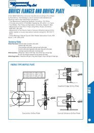
BONT ® Level GaugesOptionals for Sets of ValvesFig. 865Set Valve Plug Top and Operated by HeatingType Fig. top bottom drain vent drain vent bottom handwheel chain double weighted external internalball-check handwheel lever leverG11 737 S S S A A A A S NA A NA A NAG12 738 S S S A A A A S NA A NA A NAGP11 831 S S S A A A A S NA NA NA A NAGP12 832 S S S A A S A S NA NA NA A NAG41 747 S S A A A A S S NA A A A AG42 748 S S A A A A S S A A A A AGS41 854 S S A A A A S S NA A A A NAGS42 855 S S A A A A S S A A A A NAG51 861 S S S A NR NR A S A NA NA A NAG52 862 S S S A NR NR A S A NA NA A NAG55 863 S S S A NR NR A S A NA NA A NAKeys and Remarks to Fig. 865 S – Standard Equipment A – ApplicableNA – Not applicable NR – Possible, but not recommended1 We mean by Set the assembly of two valves (1 top and 1 bottom) for theconnection of the gauge body to the vessel The set stops fluid between vesseland level gauge in case of servicing.2 This bulletin shows steel level gauges only; the sets fitted on the levelgauges include the following patterns:- type G11 and G12, top and bottom: sleeve packed cocks; (see page 27)- type GP11 and GP12, top and bottom: piston valves; (see pages 28 and29)- type G41 and G42, “Offset” metallic seating valves, with stainless steelscrewed-in seat and stainless steel disk (see pages 30 and 31).- type GS41 and GS42, “Straight” metallic seating valves, with stainlesssteel screwed-in seat and stainless steel disk (see pages 30 and 31). type- G51, G52, G55, metallic seating valves, with Stellite faced trim (see pages32 and 33).3 Each set is usually supplied with or without some optionals according to itsoriginal design and its main application.4 EXTERNAL HEATING has electrical or steam tracing, installed on job site.By INTERNAL HEATING gauge body is inside traced for heating fluid.5 All sets can be supplied with INTERMEDIATE SUPPORT fitted on the vesselin the middle between top and bottom valve in case of very large C. toC. distance. Intermediate support usually clamps the gauge bodies only andis not in connection with the vessel inside.6 Optionals for gauge bodies on pages 36 and 37.BONT ® Gauge ValvesGeneral informationThese are the classical cocks for level gauges having a cylindrical plugwith soft tightening packing sleeve.The advantages of this design are:- circular through flow passage;- very long life of body and plug, since the elastic packing sleeve isinterposed between this two pieces;- no sensitivity to changes of temperature;- no possible plug seizure;- best performance at high temperature;- possibility to restore tightness during service by compressing packingsleeve;- complete interchangeability of worn pieces.Fig. 737-738Type G11/G12Offset Valves type G11 and G12suitable for ASME 300 and PN 400 (type G11)suitable for ASME 900 and PN 160 (type G12)These set are suitable for:- type G11 (connection to gauge by stuffing box) Fig. 737;ASME Class 300 and PN 40- type G12 (connection to gauge by screwed nipples) Fig. 738ASME Class 900 and PN 160Handles and plug are made so that each handle face downward whenthe gauge is in service, that is when shut-off (top and bottom) are openand drain cock is closed.According to the right or the left position of the shut-off cocks handle,the set (and therefore the level gauge) is named right handed or lefthanded.Centre to Centre distanceWhen these sets of cocks are chosen for the level gauge, the value ofthe minimum vessel C. to C. distance is given from the formula:- type G11: min. C. to C. = Length of body + 101 mm(CC min. = B + 101 mm) exceptionally CC min = B + 92 mm- type G12: min. C. to C. with 1/2” NPT nipples = Length of body + 50mm(CC min = B + 50 mm)Optionals- Double ended handle for chain operating;- Automatic safety ball check with removal device for bottom ballPlease apply to our sales organisation for more details and technicalInformation.Top and bottom cock1 Body2 Plug3 Tightening nut4 Packing sleeve with2 eyelets, type M2.26 Ring9 Handle♦10 Screw and washer♦11 Head joint12 Stud and nutDrain cock21 Body22 Plug23 Tightening nut24 Packing sleeve with2 eyelets, type M1.226 Ring29 Handle♦30 Screw and washer♦31 Tailpipe joint32 Tailpipe33 Union nut41 Connecting head42 P16 packing ring(16/23, 5/10)43 Stuffing box ring44 Stuffing box nut45 End tube46 Tube joint ring47 Drain joint ring52 NPT nipple54 NPT plugConnection ConnectionType G12 Type G11 ♦ Items No. 9, 10, 29 and 30 are in Carbon steel also for Material Schedule 63BONT27
BONT ® Gauge ValvesOffset Valves type GP11 and GP12suitable for ASME 300 and PN 400 (type GP11)suitable for ASME 900 and PN 160 (type GP12)Fig. 831Type GP11General informationThese sets of valves consist usually of:– 2 shut-off valves (1 top and 1 bottom)– 1 drain valve.The advantages of this design are:– excellent performance of Piston Valves, qualified according to:– API 6 FA and BS 6775: Fire Safe– TA Luft: German Clean Air, TÜV Mannheim– Druckbehälterverordnung § 22: for railway and road tankersdown to –40°C, TÜV München– easy servicing– easy dismantling of the gauge body, to facilitate replacementof the glass.These sets are suitable for:– type GP11 (connection to gauge body by stuffing box) Fig. 831ASME class 300 and PN 40– type GP12 (connection to gauge body by screwed nipples)Fig. 832:ASME class 900 and PN 160Maximum service temperature: 425°C (797°F).According to the position of the shut-off valves compared with thegauge body, the Set of valves (and therefore the level gauge) isnamed “right-handed” or “left-handed”.Fig. 831 shows a left-handed gauge. Each level gauge can be assembledright-handed or left-handedFig. 832Type GP12Connection to the vesselCan be:– flanged to customer requirements.Please state: – Standard – Size– Pressure class – FinishingThe flanges are integral with the body.Different sizes and finishing of flanges can be obtained accordingto the most used international Standards (ASME, AFNOR,BS, DIN, GOST, UNI, etc.).– screwed: – 3/4” NPT Male Plain Union– 3/4” NPT Male Spherical Union– 3/4” NPT Male Integral– welded: 3/4” Socket Welding– other connections on request.Connection to the gauge bodyCan be:– type GP11: connection by stuffing boxes and end tubes. (Fig. 831).– type GP12: connection by NPT screwed nipples (Fig. 832).In both choices the connection is made by means of head-pieces(item 41 or 51) and allows easy dismantling of the gauges for servicingand easy rotating on its axis for the best reading, providedvalves are closed even with vessel under pressure.Centre to Centre distanceWhen these sets of valves are chosen for the level gauge, the valueof the minimum vessel C. to C. distance is given from the formula:– type GP11:Minimum C. to C. = Body length + 113 mm(CC min = B + 107 mm)– type GP12:Minimum C. to C. with 1/2” NPT nipples = Body length + 81 mm(CC min = B + 81 mm)Fig. 833Material Body and Trim Remarks ApplicationSchedule wetted parts52 Forged carbon steel ASTM A 105 Stainless steel Exclusion of copper, silver and their alloys. General purpose63 Forged stainless steel AISI 316 Stainless steel AISI 316 External not wetted parts Corrosive fluids and/or fluids atof S.S. AISI 304 or 303. temperature lower than –29 °C64 Forged stainless steel AISI 316 Stainless steel AISI 316 External not wetted parts of carbon steel. Corrosive fluidsExclusion of copper, silver and their alloys.28BONT
Fig. 834 GP11 GP12Fig. 866Item PartPart Material for Material Schedule52 63 64Upper and Lower Valve0 1 Body ASTMA105 ASTM A182 F316 ASTM A182 F3162.1 Lower Valve Ring Graphite St. St. Graphite St. St. Graphite St. St.l02.2 Upper Valve Ring Graphite St. St. Graphite St. St. Graphite St. St.03 Lantern Bush Carbon Steel ASTM A479 T316 ASTM A479 T3160 4 Piston ASTM A479 T316 ASTM A479 T316 ASTM A479 T3160 6 Spindle ASTM A479 T410 ASTM A479 T304 ASTM A479 T4100 7 Handwheel Aluminium Aluminium Aluminium0 8 Handwheel Nut Carbon Steel Carbon Steel Carbon Steel0 9 Bonnet ASTM A105 ASTM A182 F316 ASTM A10510 Stud Bolt and Nut A193 B7 - A194 2H A193 B8 - A194 G8 A193 B7 - A194 2H11 Washer Carbon Steel Carbon Steel Carbon Steel12 Stud Bolt and Nut A193 B7 - A194 2H A193 B8 - A194 G8 A193 B7 - A194 2H14 Gasket Asbestosfree Asbestosfree AsbestosfreeDrain Valve21 Body ASTM A105 ASTM A182 F316 ASTM A182 F31622 Valve Ring Graphite St. St. Graphite St. St. Graphite St. St.23 Bonnet ASTM A105 ASTM A182 F316 ASTM A10524 Needle ASTM A479 T410 ASTM A479 T316 ASTM A479 T31625 Screw A193 B7 A193 B8 A193 B727 Handwheel Aluminium Aluminium Aluminium28 Handwheel Nut Carbon Steel Carbon Steel Carbon Steel41 Head GP11 ASTM A105 ASTM A479 T316 ASTM A479 T31642 Packing Ring Graphite St. St. Graphite St. St. Graphite St. St.43 Stuffing Box Ring Carbon Steel. ASTM A479 T316 ASTM A479 T31644 Stuffing Box Nut Carbon Steel ASTM A479 T316 Carbon Steel51 Head GP12 ASTM A105 ASTM A479 T316 ASTM A479 T31654 NPT Vent Plug Carbon Steel ASTM A479 T316 ASTM A479 T316Optionals– Vent Plug on the upper head-piece (standard for GP12)– Vent Valve on the upper head-piece– Automatic Safety Ball-Check, in the upper and lower valve– External tracing for heating or cooling, by electrical wire or pipe(to be made on field)– Intermediate support not connected with the vessel, for very longC. to C. distance.Material SchedulesStandard Material Schedules as per Fig. 833.Other Material Schedules available on request.Parts material is listed on Fig. 866.Request or OrderPlease state:– type of set Code GP11 or GP12– right-handed or left-handed– connections to the vessel to be detailed– optionals, if any– Material Schedule Fig. 833ServiceBefore the valves are put in service:– shut off the upper and lower valve and lightly follow up the bonnetNuts (10)– open the drain valve and lightly follow up the bonnet Screws (25)– follow up the Gaskets (14) by the Nuts (12).Spare partsOne complete set of sealing elements for 1 level gauge consists of:– 5 Valve Rings (item 2.1 - 2.2. - 22) B 10 x B 18 x 6– 2 Gaskets (item 14) B 20 x B 10,5 x 1– 2 Packing Rings (item 42) B 16 x B 23,5 x 5, for GP11 only.BONT29
BONT ® Gauge ValvesGeneral informationThese sets of valves are designed and manufactured expresslyfor use with level gauges and pressure gauges up to ASME 1500and PN 250. For use with water steam, we recommend the typeGS42 and G42, with outside screw and yoke.These valves have bolted bonnet and metallic trim with renewableseat.The valves are available:OFFSETwith Inside Screw (Fig. 747) . . . . . . . . . . .Code G41with Outside Screw and Yoke(Fig. 748) .Code G42STRAIGHTwith Inside Screw (Fig. 854) . . . . . . . . .Code GS41with Outside Screw and Yoke (Fig. 855) Code GS42They are both suitable for ASME 1500 and PN 250.- The Body is of drop forged steel.- The Bonnet is of drop forged steel and of the same material asbody. It is bolted to the body by means of four bolts with nut.The advantages of this design are quite obvious, with respectto a bonnet screwed into the body or to a bonnet connected tothe body by means of studs.- The Disk is integral on the Stem, is made of stainless steelAISI 316 and is backseating against the bonnet when the valveis full open, for easy repacking under pressure..- The Seat is of stainless steel AISI 316 (Monel or specialmaterial on request) and is easy renewable, being sealscrewed into the body.- One Safety Ball-Check of stainless steel AISI 316 (specialmaterial on request) is fitted to both valves as standard, forsafety in the event of glass breakage. The safety ball isremoved from its seat during the closing operation of the valveby means of the Stem extremity.- The Packing is made of an adequate number of preformedrings of an approved high pressure - temperature quality.Special material on request.- The Name Plate bears all prescribed indications and is fixed oneach valve.- For Operating three solutions are available:- Handwheel for plain-closing stem . . . . . . . . . . . . . . .Code 1- Weighted lever for quick-closing stem . . . . . . . . . . . .Code 2- Double-ended lever for quick-closing stem . . . . . . . .Code 3Connections to the vesselCan be:- flanged; - integral flange up to 125 mm o.D. (standard)- weld-on flange for major o.D.Please state:- Standard - Pressure class- Size - Finishing- screwed: - 3/4” NPT male union (standard)- 3/4” NPT male union spherical,- 3/4” NPT male integral.- welded : 3/4” socket welding- other connections on request.Connections to the gauge bodyCan be:- screwed 1/2” NPT female for nipple (standard) . . . . . . .Code 4- screwed 3/4” NPT female for nipple,- socket welding 1/2” or 3/4”- with union tailpipe 1/2” NPT male and union nut(standard) . . . . . . . . . . . . . . . . . . . . . . . . . . . . . . . . . . .Code 5- stuffing box for glass tube 16 mm. o.D. . . . . . . . . . . . . .Code 6Length of glass tube must be 21 mm. shorterthan the Centre to Centre distance- other connections on request.Set of Valves type G41, G42, GS41, GS42suitable for ASME 1500 and PN 250Centre to Centre distanceWhen these sets of valves are chosen for the level gauge, thevalue of the minimum vessel C. to C. distance is given by tablesfor each level gauge type, provided that the connection betweenthe level gauge and its valves is obtained by means of 1/2” NPTscrewed nipples.The min. C. to C. distance is given from the formula:- Minimum C. to C. with 1/2” NPT nipples = Body length + 90 mm(CC min = B + 90 mm)- If tailpipe connection with 1/2” NPT and Union nut is requested,50 mm must be added to the minimum CC length.- Minimum C. to C. with 3/4” NPT nipples becomes 30 mm longer.Connection to drain and ventCan be:- screwed 1/2” NPT female (standard) . . . . . . . . . . . . . . .Code 7- screwed 3/4” NPT female,- other connections on request.Optionals (see also page 29)- For Heating or Cooling the valves are available with internaltube (only G41 and G42).- For Very Low Temperature the inside screw valves (type G41and GS41) are available with prolonged stem.Material SchedulesMaterial Schedules currently manufactured on Fig. 749.Other Material Schedules with other materials on request.Part material is listed on Fig. 750.Request or OrderPlease state- OFFSET, inside screw . . . . . . . . . . . . . . . . . . . . . . .Code G41- OFFSET, outside screw . . . . . . . . . . . . . . . . . . . . . . Code G42- STRAIGHT, inside screw . . . . . . . . . . . . . . . . . . . . Code GS41- STRAIGHT, outside screw . . . . . . . . . . . . . . . . . . . Code GS42- Operating . . . . . . . . . . . . . . . . . . . . . . . . . . . .Code 1 or 2 or 3- Connections to the vessel . . . . . . . . . . . . . . . . .to be detailed- Connections to gauge body . . . . . . . . . . . . . .Code 4 or 5 or 6- Connections to drain and vent . . . . . . . . . . . . . . . . . . .Code 7- Material Schedule . . . . . . . . . . . . . . . . . .Code 52 or 55 or 63- Centre to Centre distance . . . . . . . . . . . . . . . . . . . .to be stateCodeWhen these sets are chosen with our standard variants, the use ofour Code is recommended. For instance:- 1 Set of valvesinside screw OFFSET . . . . . . . . . . . . . . . .Code G41.1.4.7.52operated by handwheel . . . . . . . . . . . . . . . . . . . . . . . . 1.4.7.52connections to gauge body screwed 1/2” NPT female. .4.7.52connections to drain and vent 1/2” NPT female. . . . . . . . . 7.52material schedule . . . . . . . . . . . . . . . . . . . . . . . . . . . . . . . . . 52Resulting CODE: . . . . . . . . . . . . . . . . . . . . . . . . G41.1.4.7.52It is to be stated in detail:- connections to the vessel,- Centre to Centre distance.MaintenanceThese sets don’t need any special maintenance. We only recommendto check from time to time the tightening of Packing gland(45) and of body-bonnet Bolts (5).Fig. 745 Type G41 and GS41 Fig. 746 Type G42 and GS4230BONT
Fig. 749Material Body bonnet and Trim and Remarks ApplicationSchedule wetted parts Ball-check52 Forged carbon steel Stainless steel Exclusion of cooper General purposeASTM A105 AISI 316 silver and their alloys55 Forged carbon steel Stainless steel External not wetted Non corrosive fluids at lowASTM A350 LF2 AISI 316 parts of S.S. temperature up to –45,6 °C (–50 °F).AISI 304 or 30363 Forged stainless steel Stainless steel External not wetted Corrosive fluids and/orAISI 316 AISI 316 parts of S.S. fluids at temperature lowerAISI 304 or 303than –45,6 °C (–50 °F)Fig. 747 Type G41 (offset 20 mm) Fig. 854 - 855 Type GS41 (straight)Type GS42 (straight)Fig. 748Type G42 (offset 20 mm)Note: remaining parts identical to:- Fig. 747 for GS41- Fig. 748 for GS 42Fig. 750Item Part Materials for Material Schedule52 55 6301 Body ASTM A105 ASTM A350 LF2 S.S. AISI 31602 Seat S.S. AISI 316 S.S. AISI 316 S.S. AISI 31603 Ball-check S.S. AISI 316 S.S. AISI 316 S.S. AISI 31604 Bonnet joint ring Soft iron S.S. AISI 316 S.S. AISI 31605 Bolt ASTM A193 B7 S.S. AISI 303 S.S. AISI 30306 Nut ASTM A194 2H S.S. AISI 303 S.S. AISI 30307 Bottom ring Carbon steel S.S. AISI 316 S.S. AISI 31608 Packing Preformed rings Preformed rings Preformed rings09.1 Handwheel Carbon steel Carbon steel Carbon steel09.2 Weighted lever Carbon steel Carbon steel Carbon steel09.3 Double-ended lever Carbon steel Carbon steel Carbon steel10 Name plate Stainless steel Stainless steel Stainless steel11 Washer Carbon steel Carbon steel Carbon steel12 Nut ASTM A194 2H S.S. AISI 303 S.S. AISI 30313 Taper plug (on request) Carbon steel S.S. AISI 316 S.S. AISI 31614 Union nut Carbon steel S.S. AISI 303 S.S. AISI 30315 Union tailpipe Carbon steel S.S. AISI 316 S.S. AISI 31616 Joint ring Suitable compressed materialItem Part Materials for Material Schedule52 55 6317 Nipple Carbon steel S.S. AISI 316 S.S. AISI 31618 Nut Carbon steel S.S. AISI 303 S.S. AISI 30319 Union tailpipe Carbon steel S.S. AISI 316 S.S. AISI 31620 Joint ring Suitable compressed material31 Stem S.S. AISI 316 S.S. AISI 316 S.S. AISI 31632 Bonnet ASTM A105 ASTM A350 LF2 S.S. AISI 31633 Bonnet flange ASTM A105 ASTM A350 LF2 S.S. AISI 30434 Gland Carbon steel S.S. AISI 304 S.S. AISI 30435 Gland nut Carbon steel S.S. AISI 304 S.S. AISI 30441 Stem S.S. AISI 316 S.S. AISI 316 S.S. AISI 31642 Stem bush S.S. AISI 410 S.S. AISI 410 S.S. AISI 41043 Bonnet ASTM A105 ASTM A350 LF2 S.S. AISI 31644 Packing gland Carbon steel S.S. AISI 304 S.S. AISI 30445 Bolt ASTM A193 B7 S.S. AISI 303 S.S. AISI 30346 Nut ASTM A194 2H S.S. AISI 303 S.S. AISI 303BONT31
BONT ® Gauge ValvesSet of Valves type G51, G52, G55suitable for ASME 2500 and PN 400General informationThese sets of valves consist of metallic seating valves.Each set is generally composed by:- 2 shut-off valves sized 1” (1 top and 1 bottom)- 1 drain valve sized 1/2”.The Set of valves fully comply with the main international Standardand specifically with ASME Code Section I, when applicable.The shut-off valves are bonnetless type, operated by handwheelwith rising non-rotating stem and stroke indicator.- The Body (1) is forged of carbon steel or stainless steel and isthe only valve part under pressure. Seat is integral of Stellitedeposited with highly specialized and automatic procedure.The Backseat ring (46) is threaded into the body and can beeasily replaced.- The Yoke (2) is always forged and is standard of carbon steel,has structural functions only and is not under pressure.Threaded outside the body and kept in place by means of onewelding tack that can be easily removed and remake forinspection or maintenance..- The Disk (3) is of alloy steel whit seating surface Stellite. Whenbackseated, disk is pulled against bonnet with axial (notrotating) movement.- The Stem (4) is of stainless steel, heat treated. Threads areACME. Being designed rising and non-rotating insures a lowerdriving and closing torque and less wear of packing rings.- The Yoke Bushing (11) is usually of special aluminium bronzeand is kept in place by two Antifriction Rings (43) and form aLocking Ring (39).- The Packing includes one Bottom Ring (5), one GraphitePacking (6), one Packing Flange (10), two Swing Bolts (8)turning for easier repacking.- The Safety Ball-check (80) are in stainless steel AISI 316 andtighten on a seat made of stainless steel AISI 316Connection to the drumCan be:- flanged- S W- B WConnection to the gauge bodyCan be:- type G51 (Fig. 861, 857): flanged on the side of the gauge body,- type G52 (Fig. 862, 858, 859): flanged on the axis of the gaugebody,- type G55 (Fig. 863, 860): flanged with the interposition of awater column,- different connections can be delivered, according to customerprescription.Fig. 863Type G55Top ValveFig. 867Item PartPart Material for Material Schedule51 64 631 Body ASTM 105 ASTM A182 F316 ASTM A182 F316+ Stellite Gr. 6 + Stellite Gr. 6 + Stellite Gr. 62 Yoke ASTM A105 ASTM A105 ASTM A1053 Disk ASTM A479 T.316 ASTM A479 T.316 ASTM A479 T.3164 Stem ASTM A182 F6 ASTM A564 T.630 ASTM A564 T.6305 Bottom rIng ASTM A479 T.316 ASTM A479 T.316 ASTM A479 T.3166 Packing Graphite Graphite Graphite8 Swing bolt ASTM A193 B7 ASTM A193 B7 ASTM A193 B89 Pin Alloy steel Alloy steel Alloy steel10 Packing flange ASTM A105 ASTM A182 F316 ASTM A182 F31611 Yoke bushing ASTM B150 - ASTM B150 - ASTM B150 -C62300 C62300 C6230012 Handwheel Carbon steel Carbon steel Carbon steel14 Disk pad ASTM A182 F6 Stainless steel Stainless steel+ treatment + treatment15 Handwheel nut Carbon steel Carbon steel Carbon steel15A Bolt nut ASTM A194 2H ASTM A194 2H ASTM A194 Gr. 820 Name plate Stainless steel Stainless steel Stainless steel23 Antirotationindicator Carbon steel. + Zinc. Carbon steel. + Zinc. Stainless Steel39 Locking ring ASTM A105 ASTM A105 ASTM A10542 Retaining ring Alloy steel Alloy steel Alloy steel43 Antifriction washer Carbon steel C70 Carbon steel C70 Carbon steel C7046 Backseat ring ASTM A564 T.630 ASTM A564 T.630 ASTM A564 T.63048 Gasket Graphite Graphite Graphite70 Connectingring Stellite Stellite Stellite80 Safety ball ASTM A479 T.316 ASTM A479 T.316 ASTM A479 T.31681 Bottom taper plugfor ball ASTM A105 ASTM A479 T.316 ASTM A479 T.31682 Top taper plugfor ball ASTM A105 ASTM A479 T.316 ASTM A479 T.31683 Welded nipple ASTM A105 ASTM A479 T.316 ASTM A479 T.31684 Connecting flange ASTM A105 ASTM A105 ASTM A479 T.31685 Lenticularjoint ring ASTM A479 T.316 ASTM A479 T.316 ASTM A479 T.31686 Joint ring Graphite Graphite GraphiteBottom Valve32BONT
Optionals (see also page 29)Following optionals can be supplied:- Vent valve on top valve,- Safety ball-check on bottom valve, vertical,- Safety ball-check on top valve, horizontal with removal device.Material Schedules (see Fig. 867)Material Schedules currently manufactured on Fig. 867.Other materials on request.MaintenanceThese sets of valves do not need particular maintenance. Wewould suggest to use good quality packings in the stuffing-box andto follow up the bolts of the packing gland from time to time.Fig. 861 Type G51 Top and bottom ValveFig. 862Type G52Top ValveBottom ValveBONT33
BONT ® Level GaugesReflex Gauge BodiesDescription and Maintenance InstructionsBolting torques- Type BR14 35 Nm - Type BR24 50 Nm- Type BR12 60 Nm - Type BR28 50 Nm- Type BR22 30 Nm - Type BR25 40 Nm- Type BR23 50 Nm1 Centre piece 8 Gauge body2 Sealing joint 9 Wedge piece3 Reflex glass 10 Tightening bolt4 Cushion joint 11 Bolt with nut5 Cover plate 12 Clamp6 U stud bolt with nuts 13 Angular piece7 O stud bolt with nutsFig. 817Type BR14Fig. 816 Type BR12 Fig. 760 Type BR22 Fig. 761 Type BR23Fig. 762 Type BR24 Fig. 819 Type BR28 Fig. 763 Type BR25Service maintenanceBefore putting in service, check the bolting torque as recommendedon top of this page. Tighten the bolts alternatively,starting from centre of gauge. To avoid glass thermal shocks duringstart-up, the gauge temperature must gradually increase in orderto allow both the metallic structure and the glass to reach the operatingtemperature. Proceed as follows: close bottom shut-off valve,completely open drain, partially open top shut-off valve to allow aminimum flow outlet of steam. Maintain flow outlet until proper temperatureis reached, then close drain valve; the condensate comingthrough top valve will fill the gauge column. At this step completelyopen very slowly bottom shut-off valve, then completely open topshut-off valve.In case during operation fluid impurities affect glass, proceed togauge washing as above describedImportant noticeMaintenance must be made immediately when:- leakage appears, even if very small. In this case: shut of and cooldown the gauge. Tighten the gauge nuts at the recommendedbolting torque;- the glass appears opaque or slightly white specially in the steamarea;- grooves of the reflex glass show sign of corrosion and/or erosionand the reading of the level is not clear.The lack of maintenance and the lack of replacement of the deterioratedparts can cause the breakage of the glass with all the relevantconsequences.Dismantling- Shut off the valves, let out the pressure and remove the levelgauge body from the valves.34BONT- Loosen the tightening bolts and remove all component pieces.- Clean the sealing and cushion surfaces very carefully, makingsure that they are clear of any remnants of joints.- Smear the threads of the tightening bolts with a thin layer ofgraphite grease;Reassembling- Fit in a new glass with new joints (never re-use joints which havealready been in service!): remember that the sealing joint must beplaced on the side where the grooves are.- Reassemble all the components in the right sequence. Tighten thebolts alternatively, starting from centre of gauge.- Never grip the level gauge body in a vice during the reassembling,but put it on a plane surface.- Never use adhesive or hermetic mastic. Remember that all surfacesmust be perfectly clean.Spare parts- When ordering spare parts please state:- type and size of the gauge body- item number of the spare part, as shown in the above list- construction material.- As regards reflex glasses and their joints, please remember that:- each type BR12, BR14 gauge is fitted with 1 reflex glasstype A (section 30x17 mm),- each type BR22, BR23, BR24, BR25, BR28 gauge is fitted with1 reflex glass type B (section 34x17 mm).For type BR13, separate instructions on request.
BONT ® Level GaugesTransparent Gauge BodiesDescription and Maintenance InstructionsBolting torques- Type BT23 50 Nm - Type BT29 80 Nm- Type BT24 50 Nm - Type BT33 80 Nm- Type BT25 40 Nm - Type BT32 90 Nm- Type BT28 80 Nm1 Centre piece 6 Cover plate2 Sealing joint 7 Bolt with nut3 Glass protection sheet 8 Stud bolt with nut(where applicable)9 Stud with nut4 Plate glass 13 Angular Piece5 Cushion joint 14 Belleville WasherFig. 764 Type BT23 Fig. 765 Type BT24 Fig. 766 Type BT25Fig. 767 Type BT28 & BT29 Fig. 814.1 Type BT33 Fig. 815.1 Type BT32Service maintenanceBefore putting in service, check the bolting torque as recommendedon top of this page. Tighten the bolts alternatively,starting from centre of gauge. To avoid glass thermal shocks duringstart-up, the gauge temperature must gradually increase in orderto allow both the metallic structure and the glass to reach the operatingtemperature. Proceed as follows: close bottom shut-off valve,completely open drain, partially open top shut-off valve to allow aminimum flow outlet of steam. Maintain flow outlet until proper temperatureis reached, then close drain valve; the condensate comingthrough top valve will fill the gauge column. At this step completelyopen very slowly bottom shut-off valve, then completely open topshut-off valve.In case during operation fluid impurities affect glass or protectionshield, proceed to gauge washing as above describedImportant noticeMaintenance must be made immediately when:- leakage appears, even if very small. In this case: shut of and cooldown the gauge. Tighten the gauge nuts at the recommendedbolting torque;- the glasses appear opaque or slightly white specially in the steamarea;- the reading of the level is not clear.The lack of maintenance and the lack of replacement of the deterioratedparts can cause the breakage of the glasses with all the relevantconsequences.Dismantling- Shut off the valves, let out the pressure and remove the levelgauge body from the valves.- Loosen and take out the tightening bolts and remove all componentpieces as well.- Clean the sealing surfaces of the centre piece and the cushionsurfaces of the cover plates very carefully, making sure that theyare clear of any remnants of joints.- Smear the threads with a thin layer of graphite grease.Reassembling- Fit in new glasses with new joints (never re-use joints whichhave already been in service!). Remember that the glass protectionsheet must be in direct contact with the inner side of theglasses (between the glass and the fluid), and that the sealingjoint must be placed on the sealing surface of the centre piece.Reassemble all the other components in the right sequence, andtighten the bolts alternatively, starting from centre of gauge.- Never grip the level gauge body in a vice during the reassembling,but put it on a plane surface.- Never use adhesive or hermetic mastic. Remember that all surfacesmust be perfectly clean.Spare parts- When ordering spare parts please state:- type and size of the gauge body- item number of the spare part, as shown in the above list- construction material.- As regards plate glasses their joints and protection sheets,remember that each level gauge is fitted with 2 plate glassestype B (section 34x17 mm).For type BC1 (bicolour), separate instructions on request.BONT35
BONT ® Level GaugesOptionals for Gauge BodiesFig. 826 Illuminator type GSI Fig. 827 Illuminator type EXGSI Fig. 828 Illuminator type EXPINFig. 820 Fig. 773-Remark 7 Fig.776 Fig. 829 Remark 7Fig. 869Fig. 773 - Non-frosting block for reflex levelgauge.Fig. 776 - Level gauge with external heatingor cooling tube. Reflex (as in figure) ortransparent.Fig. 820 - Combined level gauge with uninterruptedvisible length. Reflex (as in figure)or transparent.Fig. 826 - Illuminator type GSI, for lightingof the meniscus at water level from lowerposition, not explosion-proof.Fig. 827 - Illuminator type EXGSI, for lightingof the meniscus at water level fromlower position, explosion-proof.Fig. 828 - Illuminator type EXPIN, for diffusedlighting, explosion-proof.Fig. 829 - Non-frosting block for transparentlevel gauge, complete with illuminatortype EXPIN.Fig. 869 - Calibrated scale. The standardcalibrated scale is in stainless steel, withcalibration in cm. On request, any differentmaterial or calibration can be supplied.36BONT
BONT ® Level GaugesOptionals for Gauge Bodies - Bolting TorquesFig. 777TypeofGaugeType of glassOptionalsReflex Transparent Glass Protection Non frosting Heating or Applicable Scales Floats Uninterrupblockscooling illuminator ted visibleinternal external lengthABA-BR13TubeBDiskMica Kel-F Remark 7 internal external Remark No. Remark 9 Remark 9 Fig. 775BoltingTorqueNmeachBoltBR14 X – – – – – NA NA NA NA NA NA 1 A NA NA 35BR 12 X – – – – – NA NA NA NA NA NA 1 A NA NA 60BR22 – X – – – – NA NA NA NA A A 1 A NA A 30BR23 – X – – – – NA NA V A A A 1 A NA A 50BR24 – X – – – – NA NA V A A A 1 A NA A 50BR28 – X – – – – NA NA V A A A 1 A NA A 50BR25 – X – – – – NA NA V A A A 1 A NA A 40BR13 – – X – – – NA NA NA A A NA 1 A NA NA (Remark 8)BR26 – X – – – – NA NA V A A NA 1 A NA NA 40BR27 – X – – – – NA NA V A A NA 1 A NA NA 40BTV – – – X – – NA NA R NA A NA 1 A A – –BT23 – – – – X – A A V A A A 4 A A A 50BT24 – – – – X – A A V A A A 4 A A A 50BT25 – – – – X – A A V A A A 4 A A A 40BT28 – – – – X – A A V A A A 2, 3, 4 A A A 80BT29 – – – – X – A A V A A A 2, 3, 4 A A A 80BT33 – – – – X – A A V A A A 2, 3, 4 A A A 90BT32 – – – – X – A A V A A NA 2, 3, 4 A A A 80BT26 – – – – X – A A V A A NA 1 A NA NA 40BT27 – – – – X – A A V A A NA 1 A NA NA 40BC23 – – – – X – C NA NA NA NA NA 5 NA NA NA 50BC24 – – – – X – C NA NA NA NA NA 5 NA NA NA 50BC28 – – – – X – C NA NA NA NA NA 5 NA NA NA 80BC32 – – – – X – C NA NA NA NA NA 5 NA NA NA 80BC 1 – – – – – X C NA NA NA NA NA 6 NA NA NA (Remark 8)Keys and Remarks to Fig. 777X – Type of glass fitted in the gauge.A – Applicable.C – Compulsory.NA – Not applicableR – Recommended U shape metallic protector (Fig. 720) and/Vor acrylic resin tube protector sealed by O-Rings to thestuffing box gland (Fig. 721).– External glass protection (sheet of mica or Kel-F) may besuggested for protecting the glasses from corrosive environmental(see page 38).1 – Often not necessary. If necessary any usual lighting apparatuscan be utilised. Apply to our Technical Service fordetails.2 – Apparatus for lighting of the meniscus at water level fromlower position, not explosion-proof (Fig. 826). Type GSI.3 – Apparatus for lighting of the meniscus at water level fromlower position, explosion-proof. Please state relevantSafety Standard (Fig. 827). Type EXGSI.4 – Apparatus for diffused lighting, explosion-proof. Please staterelevant Safety Standard (Fig. 828). Type EXPIN.5 – Apparatus for bicolour lighting, explosion-proof,type EXGSIBC.6 – Apparatus for bicolour lighting, explosion-proof,type EXBSIN.7 – Non-frosting blocks:– for reflex gauge (Fig. 773)– for transparent gauge (Fig. 829) complete with1 explosion-proof illuminator.Recommended height of blocks, see page 38.8 – See specific instructions.9 – Other optionals:– Engraved scales to customer requirements.– Mirrors to transmit image below to the observer.– Closed circuit television equipment, which allows levelreading on monitor in the control room and/or transmit a 4÷20mA signal.– Fibre optic remote viewing device to transmit image in thecontrol room, by means of our Red Cherry System.Ask for peculiar bulletin.– Specific gravity glass floats can be provided in a transparentlevel gauge where the interface between two immiscibleliquids is to be observed.– Additional side connected bodies (reflex or transparent) toreach un-interrupted visible length (Fig. 820)– Heating or cooling tracing tubes for reflex or transparentgauges (Fig. 776).– For very long C to C distance, an intermediate support (notcommunicating with the vessel) can be fitted to the levelgauge body.BONT37
Sight Glasses for BONT ® Level GaugesStandards and QualityGlasses fitted in our level gauges and spare glasses comply withthe following Standards:- DIN 7081 - ONORM M 7354 - MIL G 18498 B- TGL 7210 - OMV H 2009 - Esso Eng. Spec. 123- BS 3463 - JIS B 8211 - S.O.D. Spec. 123Physical and chemical features:- Resistance to bending strain: >150 N/mm 2- Mean coefficient of linear expansion (30 °C to 300 °C):5,0 . 10 -6 . K -1 - DIN 52328- Transition temperature: 550 °C - DIN 52324.- Hydrolytic resistance: Class 1 - DIN 12111 and ISO 719- Alkali resistance: Class 2 - DIN 52322 and ISO 695- Acid resistance: Class 1 - DIN 12116Material is always borosilicate glass pre-stressed and opticallytested.”Pre-Stressed”, “hardened”, “extra hard” and similar definitionsare perfectly equivalent.We never use “soda-lime” glasses, since they have quite insufficientfeatures.Special attention shall be paid to length, width, thickness andespecially flatness tolerances. From the latter point of viewBONT® sight glasses have very strict tolerance values, definitelylower than most of the ones on the market. What above ensuresless stress and longer life of glass and joints.Reflex or transparent glassesThere are two types of sight glasses:Reflex GlassFig. 801These glasses have one smooth face (external face) and the otherface provided with moulded prismatic grooves (internal face).For application with reflex level gauges.Reflex glasses have following dimensions:Size Type A Type B Type A-BR13Length Width Thickn. Length Width Thickn. Length Width Thickn.L B S L B S L B S1 115 30 17 115 34 17 115 30 172 140 30 17 140 34 17 140 30 173 165 30 17 165 34 17 165 30 174 190 30 17 190 34 17 190 30 175 220 30 17 220 34 17 220 30 176 250 30 17 250 34 17 250 30 177 280 30 17 280 34 17 280 30 178 320 30 17 320 34 17 320 30 179 340 30 17 340 34 17 340 30 17- Sizes of glasses are now indicated by Arabic numerals (1, 2, etc.).Former size indication was in Roman numerals (I, II, etc.).Transparent GlassesFig. 802Transparent glasses have following dimensions:Size Type A Type B Type A-BT12Length Width Thickn. Length Width Thickn. Length Width Thickn.L B S L B S L B S1 115 30 17 115 34 17 – – –2 140 30 17 140 34 17 – – –3 165 30 17 165 34 17 163 27.6 16.84 190 30 17 190 34 17 188 27.6 16.85 220 30 17 220 34 17 218 27.6 16.86 250 30 17 250 34 17 248 27.6 16.87 280 30 17 280 34 17 278 27.6 16.88 320 30 17 320 34 17 318 27.6 16.89 340 30 17 340 34 17 338 27.6 16.8- Sizes of glasses are now indicated by Arabic numerals (1, 2, etc.).Former size indication was in Roman numerals (I, II, etc.).- Transparent glasses Type A (cross section 30 x 17 mm) areonly spare parts for old pattern level gauges manufactured byus before 1945.- Transparent glasses type A-BT12are only spare parts forFig. 792.4transparent bodies type BT12, nomore in production.- A special transparent glass isthe round glass for applicationwith high pressure(usually bicolour) level gauges.This glass is a small disc(Fig. 792.4) with very stricttolerances.Joints for glasses- Each sight glass is usually supplied with 2 joints (1 sealing joint+ 1 cushion joint).- Length and width of joint are the same as those of the respectiveglass.- Reflex glasses type A-BR13 - for fitting in reflex gauges typeBR13 - need special sized joints. See maintenance instructions.- Transparent glasses type A-BT12 - for fitting in transparentgauges type BT12, no more in production - need special sizedjoints. See maintenance instructions.Protection for glassesWhen glass protection against corrosive fluids is to be taken inconsideration (including boiler water pressured over 35 bar), youmust remember that only smooth surfaces can be shielded bysmooth sheets having same length and width as sight glass.Therefore:- reflex glasses: only external face can be shielded by micasheets or other materials against corrosive environmental agents,- transparent glasses: both faces can be shielded by mica ortransparent polytrifluorochloroethylene (Kel-F) sheets.Protection of the internal glass face in contact with fluid isusually sufficient.Mica sheets inside level gauges are always recommended forapplication with water steam: thickness of mica sheets isusually 0.15 to 0.20 mm.Non-frosting BlocksFrost on gauge obstructing level reading could develop when levelgauge operates at fairly low temperature.In such cases non-frosting block of transparent acrylic resin mustbe fastened and sealed outside the gauge body.This block shall protrude according to the thickness of the frost(see Fig. 773 and 829).Recommended protrusion:Workingtemperature of fluidProtrusionof block120 °C through –19 °C ........................................... 038 mm–120 °C through –49 °C ..........................................075 mm–150 °C through –99 °C ......................................... 150 mm–100 °C and lower ................................................. 200 mmThese glasses have both smooth faces.For application with transparent level gauges.38BONT
°C °F °C °F °C °F °C °Fbar °CConversion Table from °C to °F–270 –454–260 –436–250 –418–240 –400–230 –382–220 –364–210 –346–200 –328–190 –310–180 –292–170 –274–160 –256–150 –238–140 –220–130 –202–120 –184–110 –166–100 –148–095 –139–090 –130–085 –121–080 –112–075 –103–070 –094–065 –085–060 –076–055 –067–050 –058–045 –049–040 –040–035 –031–030 –022–025 –013–020 –004–017,8 000–015 5–010 14–005 230 325 4110 5015 5920 6825 7730 8635 9540 10445 11350 12255 13160 14065 14970 15875 16780 17685 18590 19495 203100 212105 221110 230115 239120 248125 257130 266135 275140 284145 293150 302155 311160 320165 329170 338175 347180 356185 365190 374195 383200 392205 401210 410215 419220 428225 437230 446235 455240 464245 473250 482255 491260 500265 509270 518275 527280 536285 545290 554295 563300 572305 581310 590315 599320 608325 617330 626335 635340 644345 653350 662355 671360 680365 689370 698375 707380 716385 725390 734395 743400 752405 761410 770415 779420 788425 797430 806435 815440 824445 833450 842455 851460 860465 869470 878475 887480 896485 905490 914495 923500 932505 941510 950515 959520 968525 977530 986535 995540 1004545 1013550 1022555 1031560 1040565 1049570 1058575 1067580 1076585 1085590 1094595 1103600 1112605 1121610 1130615 1139620 1148625 1157630 1166635 1175640 1184645 1193650 1202655 1211660 1220665 1229670 1238675 1247680 1256685 1265690 1274695 1283700 1292710 1310720 1328730 1346740 1364750 1382760 1400770 1418780 1436790 1454800 1472810 1490820 1508830 1526840 1544850 1562860 1580870 1598880 1616890 1634900 1652910 1670920 1688930 1706940 1724950 1742960 1760970 1778980 1796990 18141000 18321020 18681040 19041060 19401080 19761100 20121120 20481140 20841160 21201180 21561200 21921220 22281240 22641260 23001280 23361300 23721320 24081340 24441360 24801380 25161400 25521420 25881440 26241460 26601480 26961500 27321520 27681540 28041560 28401580 28761600 29121620 29481640 29841660 30201680 30561700 30921750 31821800 32721850 33621900 34521950 35422000 36322050 37222100 38122150 39022200 39922250 40822300 41722350 42622400 43522450 44422500 45322550 46222600 47122650 48022700 48922750 49822800 50722850 51622900 52522950 53423000 5432Pressure/Temperature Table for Saturated Water Steam1,0 99,11,5 110,72,0 119,62,5 126,73,0 132,83,5 138,14,0 142,94,5 147,25,0 151,15,5 154,76,0 158,06,5 161,17,0 164,17,5 167,18,0 169,68,5 172,29,0 174,59,5 176,710 179,011 183,212 187,013 190,714 194,115 197,316 200,417 203,318 206,119 208,820 211,422 216,224 220,726 225,028 228,930 232,735 241,440 249,145 256,250 262,755 268,660 274,265 279,570 284,475 289,180 293,685 297,890 301,995 305,8100 309,5105 313,3110 316,5115 319,8120 323,1125 326,2130 329,3135 332,2140 335,1145 337,8150 340,6155 343,2160 345,7165 348,3170 350,6175 353,0180 355,4185 357,5190 359,8195 361,9200 364,1205 366,1210 368,1215 370,2220 372,0225 374,0BONT39
NSWNSWSydney13WyongSirius-Road,HeadLaneOfficeCove NSW 2066Tel:10 Hereford+61 (0)2Street,9428 7377Berkeley Vale NSW 2261Fax:PO Box+615010(0)2 9428Chittaway7379NSW 2261Email:Tel: +61sydney@hmagroup.com.au(0)2 4389 6191Fax:+ 61 (0)2 4389 6199Wyong Email: info@hmagroup.com.au- Head Office10 Hereford Street, Berkeley Vale NSW 2261POArtarmonBox 5010 Chittaway NSW 2261Tel:48 Whiting+61 (0)2Street,4389Artarmon6191NSW 2064Fax:PO Box+61177,(0)2Artarmon4389 6199NSW 2064Email:Tel:+61info@hmagroup.com.au(0)2 9432 7300Fax: +61 (0)2 9432 7399Email: artarmon@hmagroup.com.auQLDBrisbane Gladesville4rd 33-37 Floor, College 49 Sherwood Street, Gladesville Road, Toowong NSW 2111 QLD 4066PO Tel: Box +61 106, (0)2 Toowong 9816 3377 QLD 4066Tel: Fax: +61 +61 (0)7 (0)23859 9816 6800 3806Fax: gladesville@hmagroup.com.au+61 (0)7 3859 6869Email: brisbane@hmagroup.com.auVicMackayMelbourne22-30 Southgate Drive,PO Box 647, Morwell VIC 3840Southgate Industrial Park, Paget QLD 4740Tel:+ 61 (0)3 5136 8445PO Box 6221, Mackay Mail Centre QLD 4741Mobile: +61 (0)429 176 688Tel: +61 (0)7 4998 6900Email: melbourne@hmagroup.com.auFax: +61 (0)7 4998 6999Email: Morwell mackay@hmagroup.com.au8 Jones Road, Morwell VIC 3840GladstonePO Box 647, Morwell VIC 38409 Neil Street, Gladstone QLD 4680Tel:+ 61 (0)3 5136 8400PO Box 1731, Gladstone QLD 4680Fax: +61 (0)3 5136 8499Tel: +61 (0)7 4978 3128Email: morwell@hmagroup.com.auFax: +61 (0)7 4978 3127Email: gladstone@hmagroup.com.auSATownsvilleAdelaidePOPOBoxBox347,1280,AitkenvaleNorth HavenQLDSA48145018Tel:Tel: +61+61(0)8(0)78341472880676300Fax:Fax:+61+61(0)7(0)84728834163888067Mobile:Mobile:+61+61(0)417(0)437996460694032Email:Email:townsville@hmagroup.com.auadelaide@hmagroup.com.auWAWAPerthPerth119 Dowd Street, Welshpool WA 6106Unit 1, 34 Ledgar Road, Balcatta WA 6021Tel: +61 (0)8 6254 9500Tel: +61 (0)8 9345 3688Fax: +61 (0)8 6254 9599Fax:+61 (0)8 9344 8707Email: perth@hmagroup.com.auEmail: perth@hmagroup.com.auVICQLDMelbournePO Brisbane Box 204, Narre Warren VIC 3805Mobile: 4th Floor, +61 49 (0)429 Sherwood 176 688Road, Toowong QLD 4066Email: PO Box melbourne@hmagroup.com.au106, Toowong QLD 4066Tel: +61 (0)7 3859 6800MorwellFax: +61 (0)7 3859 68698 Jones Road, Morwell VIC 3840Email: brisbane@hmagroup.com.auPO Box 647, Morwell VIC 3840Tel: Mackay + 61 (0)3 5136 8400Fax: 22-30 +61 Southgate (0)3 5136 Drive, 8499Email: Southgate morwell@hmagroup.com.auIndustrial Park, Paget QLD 4740PO Box 6221, Mackay Mail Centre QLD 4741SA Tel: +61 (0)7 4998 6900Fax:+61 (0)7 4998 6999AdelaideEmail: mackay@hmagroup.com.auPO Box 1280, North Haven SA 5018Tel: Gladstone +61 (0)8 8341 8067Fax: 9 Neil +61 St, (0)8 Gladstone 8341 8067 QLD 4680Mobile: PO Box +61 1731, (0)437 Gladstone 460 032QLD 4680Email: Tel: +61 adelaide@hmagroup.com.au(0)7 4978 3128Fax: +61 (0)7 4978 3127Email: gladstone@hmagroup.com.auNEW ZEALANDHamilton TownsvilleUnit PO 14, Box 9 347, Karewa Aitkenvale Place, Pukete, QLD 4814 Hamilton NZ 3200PO Tel: Box +61 10102, (0)7 4728 Te Rapa, 6300 Hamilton NZ 3241Tel: Fax: +64 +61 (0)7 (0)7 847 4728 1880 6388Fax: Mobile: +64 (0)7 +61 847 (0)417 1883 996 694Email: hamilton@hmagroup.co.nztownsville@hmagroup.com.auWellingtonNEW zEALANDTel: +64 (0)7 847 1880Fax: Hamilton +64 (0)7 847 1883Mobile: PO Box +64 89, 272 Ngaruawahia 612 744 3720 New ZealandEmail: Tel: +64 wellington@hmagroup.co.nz(0)7 824 5040Fax: +64 (0)7 824 5041DunedinEmail: hamilton@hmagroup.co.nzTel: +64 (0)27 511 6694Fax: Wellington +64 (0)7 847 1883Email: PO Box dunedin@hmagroup.co.nz13104, Johnsonville 6037 Wellington New ZealandTel: +64 (0)4 891 0312Fax: +64 (0)4 891 0313Email: wellington@hmagroup.co.nzHalley & Mellowes Australasia Group of Companies01/11 HM086