System Overview - Telesis Technologies, Inc.
System Overview - Telesis Technologies, Inc.
System Overview - Telesis Technologies, Inc.

You also want an ePaper? Increase the reach of your titles
YUMPU automatically turns print PDFs into web optimized ePapers that Google loves.
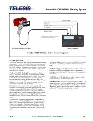
<strong>System</strong> <strong>Overview</strong><br />
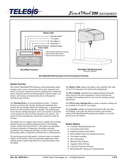
The <strong>Telesis</strong> ® BenchMark ® 200 marking system permanently prints<br />
messages into a variety of materials such as steel, aluminum, and<br />
plastic. An electric solenoid accelerates a hardened pin to indent dot<br />
matrix characters into the item being marked. Character shape, size,<br />
density, and location are determined by the user through the<br />
marking system software.<br />
The Marking Head is an electromechanical marker. A thermoformed<br />
cover houses the internal, mechanical components that<br />
position the pin cartridge and fire the marking pin. A spring returns<br />
the pin to its idle position within the cartridge. The marking head<br />
moves the pin cartridge through X- and Y-axis motions to reach the<br />
correct position for each dot of the characters to be marked. The<br />
system software automatically controls pin extension to mark the<br />
message.<br />
The marker uses two stepper-motor drives to rapidly and accurately<br />
position the pin at coordinate-defined locations in the marking<br />
window within 0.032 mm (0.00125"). The marker accommodates<br />
the rigorous dynamics of impacting, rebounding, and rapid<br />
positioning of the marking pin through a system of rigid rails and<br />
ball bearing saddles, timing belts, and direct-drive, toothed pulleys.<br />
The pin design permits high quality, consistent marks on irregular,<br />
slightly curved surfaces. It also accommodates applications where<br />
marking surfaces cannot be positioned at a consistent distance from<br />
the marker.<br />
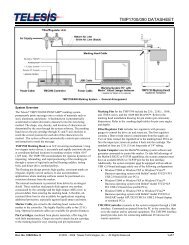
BenchMark200 Marking <strong>System</strong> General Arrangement Drawing<br />
DATASHEET<br />
The Marker Cable connects the marker to the controller. The cable<br />
is 4 m (13 ft.) long and is pre-wired to the marking head.<br />
The Pin Cartridge, machined from engineered plastic materials,<br />
offers long life with little maintenance. Screws attach the pin<br />
cartridge to the marking head for easy removal, cleaning, and pin<br />
replacement.<br />
The 25XLE-series Marking Pins are made of tungsten carbide and<br />
are available in 30° and 45° cone angles.<br />
The Controller includes an integrated keyboard with a four line<br />
LCD display. It provides the electrical interface and software<br />
control of the BenchMark200 marking head. (Refer to Controller<br />
Specifications for details.)<br />
<strong>System</strong> Options<br />
• Controller Mounting Bracket Kit<br />
• Foot Switch (Start Print)<br />
• Pushbutton Station (Start/Abort)<br />
• RD3 and RD5 Theta Axis Rotational Fixtures<br />
• Tool Stand Assembly<br />
• Bar Code Scanner<br />
• Backup Utility Software<br />
• Upgrade Utility Software<br />
• Logo/Font Generator Software<br />
• BenchMark200+ Enhanced Communications<br />
Doc. No. 30353 Rev. – © 2008 <strong>Telesis</strong> <strong>Technologies</strong>, <strong>Inc</strong>. – All Rights Reserved 1 of 6
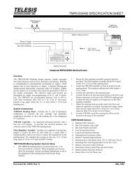
<strong>System</strong> Setup<br />
1. Mount the marking head to a suitable surface or tool post using<br />
four M8-1.25 bolts. Mounting bolts must extend into the<br />
back plate at least 9mm (0.375 in.) but not more than<br />
12mm (0.5 in.). See Mounting Drawing (above) for details.<br />
2. Adjust pin stroke for proper pin impact depth.<br />
Note: The controller is not a sealed unit. Protect it from<br />
potentially damaging conditions and contaminants. Do<br />
not block case vents. Ensure the marking system is<br />
electrically isolated from any devices that may generate<br />
extreme electromagnetic interference (EMI).<br />
3. Locate controller as close as practical to marking head.<br />
Standard marker cable length is 4 m (13 ft.).<br />
4. Ensure controller power switch (on back panel) is OFF;<br />
connect power cable to controller.<br />
5. Connect marker cable from marking head to controller;<br />
tighten securely.<br />
6. Position controller power switch to ON (on back panel) to<br />
start the marking system software.<br />
BenchMark200 Marking Head Mounting Drawing<br />
BenchMark200 Marking Head<br />
DATASHEET<br />
Specifications. The BenchMark200 marking head specifications<br />
are subject to change without prior notice.<br />
DIMENSIONS 226.6 x 240.1 x 255.3 mm (pin retracted)<br />
(H x W x D) 8.92 x 9.45 x 10.05 in<br />
230.4 x 240.1 x 255.3 mm (pin extended)<br />
9.07 x 9.45 x 10.05 in<br />
WEIGHT 5.63 Kg (12.375 lbs.) marking head and cable<br />
5.08 Kg (11.185 lbs.) marking head only<br />
OPERATING TEMP. 0° to 50° C (32° to 122° F), non-condensing<br />
MARKING AREA 100 x 100 mm (4.0 x 4.0")<br />
PIN TYPES 25XLE-series<br />
PIN MATERIAL Tungsten Carbide<br />
Marking Characteristics. The BenchMark200 can accommodate<br />
character sizes from .762 to 100 mm (.030 to 4.0") in .025 mm<br />
(.001") increments. Characters can be rotated in 1° increments with<br />
printing resolutions from 5 dots/cm (10 dots/in.) to 75 dots/cm<br />
(200 dots/in.) for an engraved look.<br />
Marking Speeds. Generally, the system will mark three characters<br />
per second using 5x7 font, 3 mm (.118") high, 2mm (.080") wide<br />
characters. Speeds will vary slightly depending on the selected<br />
character size, style, and dot density. Specific times can be verified<br />
by a <strong>Telesis</strong> representative.<br />
Doc. No. 30353 Rev. – 2 of 6
BenchMark200 Marking Head (continued)<br />
Marking Noise. Although every attempt is made to reduce noise,<br />
the material being marked significantly influences the noise level.<br />
For example, marking a solid lead block produces less noise than<br />
marking a thin-walled steel pipe.<br />
Pin Life. Pin life depends largely on the type of material being<br />
marked, how hard or abrasive it is, and the required marking depth.<br />
On typical metals with a hardness of Rockwell Rb47, marking at a<br />
depth of .127 mm (.005"), carbide pins average approximately<br />
9 million impressions before needing sharpened.<br />
Marking Depth. The BenchMark200 can obtain a marking depth<br />
of .127 mm (.005") in mild steel (Rb53) using a 25XLE carbide pin<br />
with a 45° cone angle. The depth of mark can be adjusted over a<br />
significant range by changing the impact force (via software<br />
parameter) or by changing the impact distance (pin stroke).<br />
Specific depths can be verified by a <strong>Telesis</strong> representative.<br />
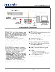
BenchMark Controller Mounting Drawing<br />
DATASHEET<br />
BenchMark Controller<br />
Specifications. The BenchMark controller specifications are<br />
subject to change without prior notice.<br />
DIMENSIONS see BenchMark Controller Mounting Drawing<br />
RATING NEMA 1 (I.P. 30)<br />
WEIGHT 2.15 Kg (4.75 lb.)<br />
OPERATING TEMP. 0° to 50°C (32° to 122° F), non-condensing<br />
REQUIRED POWER 95-130 VAC, 2 amps, 50-60 Hz single phase<br />
200-250 VAC, 1 amp, 50-60 Hz single phase<br />
INPUT SIGNALS 12 to 24 VDC (optional, customer-supplied)<br />
Doc. No. 30353 Rev. – 3 of 6
BenchMark Controller (continued)<br />
Environmental Considerations. The following environmental<br />
considerations must be taken into account when installing the<br />
BenchMark controller.<br />
Contaminants. The vented and fan-cooled controller is rated<br />
NEMA 1 (IP30). Accordingly, in environments where solid<br />
and/or liquid contaminants are present, the possibility exists that<br />
these contaminants can be drawn into the controller and possibly<br />
result in failure of a number of electronic components. For that<br />
reason, in these types of environments, the controller must be<br />
located in a sealed industrial enclosure.<br />
EMI Susceptibility. Although the system has been found to be<br />
in compliance with pertinent susceptibility standards, care should<br />
be taken when installing near welders and other extreme<br />
generators of electromagnetic interference (EMI). Particular care<br />
should be taken to ensure welder currents are not injected<br />
through the marking head chassis. The marking head chassis is<br />
connected to the electrical service earth ground through the<br />
marking head cable. The marking head should be electrically<br />
isolated from all surfaces which could become part of a welder<br />
current path.<br />
Back Panel. The power entry module contains fuses for circuit<br />
protection and connects the controller to facility electrical power.<br />
The back panel also provides a Marker port for connecting the<br />
marking head and an Aux Axis port for connecting an optional<br />
<strong>Telesis</strong> rotary drive (Theta Axis) fixture.<br />
Input Control Signals. The controller is configured for VDC input<br />
only. The TTL Input port may be used to connect a remote foot<br />
switch or remote pushbutton station for Start Print commands. The<br />
Discrete Input port may be used for remote Start Print and Abort<br />
signals. Cable connectors and connector pins are supplied with the<br />
controller for constructing appropriate interface cables.<br />
START PRINT Input signal, begins print cycle<br />
ABORT Input signal, aborts print cycle<br />
INPUT COMM For all inputs (+ or – supply)<br />
DATASHEET<br />
<strong>System</strong> Software. The marking system software is permanently<br />
installed in the controller. It provides the user interface for the<br />
operator to control the marker. The software also provides a library<br />
for storing, loading, and editing user-defined patterns. Patterns are<br />
files stored in the controller memory. The controller can store up to<br />
75 patterns. Each pattern contains one or more fields. A field<br />
defines a single object and how it will be printed. Fields may<br />
define text strings, arcs, arc text strings, Go-To or Pause<br />
commands, or machine-readable data matrix symbols. Text fields<br />
may include alphanumeric characters, symbols, and special<br />
message flags. The message flags automatically insert data into the<br />
text string, such as serial numbers, times, and dates.<br />
PC Utilities. The Host port on the controller back panel is used<br />
for connecting to an optional, customer-supplied PC to access<br />
<strong>Telesis</strong> software utilities. Utility software may be used to backup<br />
patterns stored in the controller, to download a custom font to the<br />
controller, or to download controller software upgrades.<br />
Bar Code Scanner Interface. The Host port also allows you to<br />
connect an optional bar code scanner. When the bar code scanner<br />
interface is used, the marking system reads the scanned data from<br />
the bar code, then inserts it into the variable text field of the<br />
current pattern. If more than one variable text field exists in the<br />
pattern, the operator must select which field is to receive the data.<br />
Doc. No. 30353 Rev. – 4 of 6
BenchMark200+ Enhanced Communications<br />
The BenchMark200+ Enhanced Communications option allows you<br />
to use the controller’s input/output signals and host communication<br />
capabilities to remotely control the marker.<br />
The I/O port allows you transmit I/O signals between the<br />
controller and a remote I/O device. The I/O device can remotely<br />
select patterns to be loaded and start or abort the marking cycle.<br />
Output signals from the marker may be transmitted to the I/O<br />
device to report its status.<br />
The TTL I/O port allows you to start printing operations using a<br />
Programmable Logic Controller (PLC) or by connecting a<br />
simple START PRINT contact closure.<br />
The Host port allows an RS-232 device to transmit data, select<br />
patterns for printing, and control the marker operation.<br />
Optionally, the host interface supports RS-485 communications<br />
for networking multiple markers to the same controller.<br />
I/O Control Signals. The TMC420 is configured for DC I/O only.<br />
The TTL I/O Port may be used to connect a remote pushbutton<br />
control for Start Print and Abort commands. The I/O Port may be<br />
used to connect a PLC or other DC I/O source. The I/O Port allows<br />
remote control of pattern selection, printing, aborting, placing the<br />
marker online, and monitoring of the Ready and Done output<br />
signals. Cable connectors and connector pins are supplied with the<br />
controller for constructing appropriate interface cables.<br />
START PRINT Input signal, begins print cycle<br />
SEL_0, 1, 2, 3 * Input signals, remote pattern selection (15* max.)<br />
SEL_3 * Input signal, marker online<br />
ABORT Input signal, aborts print cycle<br />
INPUT COMM For all inputs (+ or – supply)<br />
READY Output signal, ready for message or start print<br />
DONE Output signal, print cycle complete<br />
OUTPUT COMM For all outputs (+ or – supply)<br />
* <strong>System</strong> software allows SEL_3 signal to be configured for remotely<br />
selecting patterns or for remotely placing the marker online. If used<br />
for marker online, pattern selection is reduced to 7 patterns (max).<br />
Serial Interface. The Host Port is used for RS-232 and RS-485<br />
communications with serial devices such as a host computer or bar<br />
code scanner. Up to 31 controllers may be used in a multi-drop<br />
configuration using the RS-485 interface. The host computer can<br />
load patterns, download messages, place the marker on/offline, and<br />
monitor system errors. (See Serial Communications for details.)<br />
DATASHEET<br />
Serial Communications. The Host Port may be used for either<br />
RS-232 or RS-485 communication. The RS-232 interface is most<br />
often used with remote devices such as bar code readers or host<br />
computers. The RS-485 interface is normally used for long<br />
transmission distances or multi-drop networks of up to 31 TMC420<br />
controllers. The serial port may be configured to communicate<br />
using either the <strong>Telesis</strong> Programmable Protocol or <strong>Telesis</strong> Extended<br />
Protocol. The following describes the serial data character format<br />
on all transmissions to and from the TMC420 controller.<br />
• Asynchronous<br />
• 1200, 2400, 4800, 9600, or 19200 baud-host<br />
• One Start Bit<br />
• One or Two Stop Bit(s)<br />
• Seven or Eight Data Bits<br />
• None, Even or Odd Parity<br />
Programmable Protocol is used where very simple one-way<br />
communications are required (such as with bar code scanners).<br />
Programmable Protocol provides no error checking or<br />
acknowledgment of the transmitted data. Note that XON/XOFF<br />
Protocol applies even when Programmable Protocol is selected.<br />
Starting Character specifies where the software begins to count<br />
character positions. This number must be entered in ASCII<br />
decimal format such as 2 for STX.<br />
Terminating Character identifies the end of transmitted string<br />
(usually ASCII carriage return character, decimal 13).<br />
Character Position counted from the starting character ignoring<br />
all characters preceding it.<br />
Character Length accepts variable length messages (if set to 0)<br />
or messages of a pre-specified, fixed number of characters.<br />
Ignore Character identifies the character to ignore when sent<br />
from the host (usually ASCII line feed character, decimal 10).<br />
Message Type allows message-type recognition which defines<br />
how the marking system will use data it receives from the host..<br />
P loads a specific pattern identified by data extracted from host<br />
V updates first variable text field with data extracted from host<br />
1 overwrites first text field with data extracted from the host<br />
Q updates text in first query buffer with data extracted from host<br />
0 indicates that host will provide message type, field number<br />
(if applicable), and data; delegates message type selection to<br />
the host on message-by-message basis. The host message<br />
must use the format Tnn where:<br />
T = P, V, 1, or Q to indicate the message type.<br />
nn = two-digit number to indicate field number or<br />
query text buffer where data will be placed. Note<br />
that a number is not used with Message Type P.<br />
= pattern name (Message Type P) or field data<br />
(Message Types V, 1, or Q), as applicable.<br />
Doc. No. 30353 Rev. – 5 of 6
Extended Protocol includes error checking and transmission acknowledgment. It should be used in applications where serial<br />
communication is a vital part of the marking operation. Extended Protocol must be used in multi-drop applications.<br />
All communications are carried out in a master-slave relationship with the host being the master. Only the master has the ability<br />
to initiate communications. If the host does not receive a response within three seconds, it should re-transmit its original message. If<br />
no response is received after three tries, it should declare the link to be down.<br />
The following describes the message format as sent from the master to the TMC420 controller.<br />
SOH TYPE [##] STX [DATA TEXT] ETX BCC CR<br />
SOH ASCII Start of Header character (001H). The controller<br />
ignores all characters received prior to the SOH.<br />
TYPE A single, printable ASCII character that defines the<br />
meaning (type) and content of the message downloaded from the<br />
host, where:<br />
1 overwrites the specified field of currently loaded pattern,<br />
using the format 1nn where nn is the field number.<br />
V updates specified variable text field of currently loaded pattern,<br />
using the format Vnn where nn is the field number.<br />
Q updates specified query buffer with the data received from<br />
host, using the format Qnn where nn is the buffer<br />
number.<br />
P specifies pattern name to be loaded for printing<br />
O resets marker and places it online<br />
G initiates a print cycle to mark the currently loaded pattern<br />
I requests the marker output status; returns a single-digit<br />
hexadecimal value to report state of READY and DONE:<br />
Returned Value DONE READY<br />
0 off Off<br />
1 off ON<br />
2 ON Off<br />
3 ON ON<br />
S requests the marker error status; returns a value that<br />
represents a particular type of error:<br />
Returned Value TYPE OF ERROR<br />
0x0000 (no error)<br />
0x0001 ONLINE_ERROR<br />
0x0002 PATTERN_LOAD_ERROR<br />
0x0004 DISALLOWED_NO_PATTERN<br />
0x0008 DISALLOWED_OFFLINE<br />
0x0010 PATTERN_FIELD_ERROR<br />
0x0020 MARKER_ABORTED_ERROR<br />
0x0080 PIX_OUT_OF_RANGE_ERROR<br />
0x0100 RAM_ERROR<br />
0x0200 SN_RANGE_ERROR<br />
DATASHEET<br />
[##] Two optional ASCII decimal digits that specify the Station ID<br />
number for use in multi-drop network applications. The ID may<br />
range from 00-31. Note that “00” is reserved for applications where<br />
only one controller is used. In such applications, this field may be<br />
eliminated and “00” will be assumed.<br />
STX ASCII Start of Text Character (002H).<br />
[DATA TEXT] Optional field that may be required for certain<br />
message types.<br />
ETX ASCII end of text character (003H).<br />
BCC Optional Block Check Code that is generated and sent to<br />
improve link reliability by providing fault detection. The BCC is<br />
calculated by taking an eight bit addition of the TYPE and DATA<br />
TEXT characters and transmitting them as a three digit ASCII<br />
decimal number in the range from 000 to 255. If the sum is greater<br />
than 255, the most significant bit overflows and is discarded.<br />
CR ASCII Carriage Return Character (00DH).<br />
<strong>Telesis</strong> and BenchMark are registered trademarks of <strong>Telesis</strong><br />
<strong>Technologies</strong>, <strong>Inc</strong>. in the United States and/or other countries.<br />
Doc. No. 30353 Rev. – 6 of 6