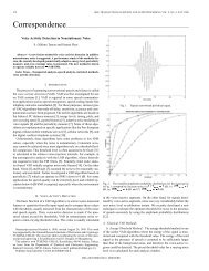
Thesis (PDF) - Signal & Image Processing Lab
Thesis (PDF) - Signal & Image Processing Lab
Thesis (PDF) - Signal & Image Processing Lab

You also want an ePaper? Increase the reach of your titles
YUMPU automatically turns print PDFs into web optimized ePapers that Google loves.
SELF-DUAL MORPHOLOGICAL<br />
OPERATORS BASED ON TREE<br />
REPRESENTATIONS OF IMAGES<br />
ALLA VICHIK
SELF-DUAL MORPHOLOGICAL OPERATORS<br />
BASED ON TREE REPRESENTATIONS OF<br />
IMAGES<br />
RESEARCH THESIS<br />
Submitted in Partial Fulfillment of the Requirements<br />
For the Degree of Master of Science<br />
in Electrical Engineering<br />
Alla Vichik<br />
SUBMITTED TO THE SENATE OF THE TECHNION — ISRAEL INSTITUTE OF TECHNOLOGY<br />
NISAN, 5766 HAIFA MARCH, 2006
The Research <strong>Thesis</strong> was done under the supervision of<br />
Dr. Renato Keshet and Prof. David Malah at the Electrical<br />
Engineering department.<br />
I would like to convey my deepest gratitude to Dr. Renato Keshet and<br />
Prof. David Malah for their extremely devoted guidance and support<br />
throughout the research. I would like to thank all the staff of <strong>Signal</strong><br />
and <strong>Image</strong> <strong>Processing</strong> <strong>Lab</strong> and especially to Nimrod Peleg, for the<br />
excellent organization and the warm relation and Ziva Avni for the<br />
technical support. Finally, I thank my own family, which accompany<br />
me in all steps.
Contents<br />
1 Introduction 5<br />
1.1 Self-Duality . . . . . . . . . . . . . . . . . . . . . . . . . . . . . . . . 5<br />
1.2 Background and motivation . . . . . . . . . . . . . . . . . . . . . . . 6<br />
1.3 Original contributions . . . . . . . . . . . . . . . . . . . . . . . . . . 8<br />
1.4 Summary and thesis organization . . . . . . . . . . . . . . . . . . . . 9<br />
2 Theoretical Background 12<br />
2.1 Graph theory notions . . . . . . . . . . . . . . . . . . . . . . . . . . . 12<br />
2.2 Known tree representations . . . . . . . . . . . . . . . . . . . . . . . 13<br />
2.2.1 Max-Tree and Min-Tree . . . . . . . . . . . . . . . . . . . . . 14<br />
2.2.2 Binary Tree . . . . . . . . . . . . . . . . . . . . . . . . . . . . 16<br />
2.2.3 Tree of Shapes . . . . . . . . . . . . . . . . . . . . . . . . . . 17<br />
2.3 Theoretical Background on semilattices . . . . . . . . . . . . . . . . . 18<br />
2.3.1 Complete Semilattices and Lattices . . . . . . . . . . . . . . . 18<br />
2.3.2 Morphology on Semilattices . . . . . . . . . . . . . . . . . . . 20<br />
2.3.3 Supremum and Dilations . . . . . . . . . . . . . . . . . . . . . 21<br />
2.4 Shape Tree Semilattice Background . . . . . . . . . . . . . . . . . . . 23<br />
2.4.1 Tree of Shapes . . . . . . . . . . . . . . . . . . . . . . . . . . 23<br />
2.4.2 Inf-Semilattice of Binary Sequences . . . . . . . . . . . . . . . 25<br />
2.4.3 <strong>Image</strong>s of Shape Sequences . . . . . . . . . . . . . . . . . . . . 26<br />
2.4.4 Inf-Semilattice of <strong>Image</strong>s of Shape Sequences . . . . . . . . . . 27<br />
2.4.5 Conclusion . . . . . . . . . . . . . . . . . . . . . . . . . . . . . 31<br />
2.5 Alternating Sequences Semilattice Background . . . . . . . . . . . . . 31<br />
2.5.1 Boundary Topographic Distance (BTD) . . . . . . . . . . . . 31<br />
2.5.2 An extension of boundary topographic distance definition . . . 32<br />
2.5.3 Boundary Topographic Variation (BTV) Transform . . . . . . 32<br />
2.5.4 Semilattice in BTV Domain . . . . . . . . . . . . . . . . . . . 35<br />
iii
iv CONTENTS<br />
3 Implementation of BTVT 37<br />
3.1 Topographic Distance Tree definition . . . . . . . . . . . . . . . . . . 37<br />
3.2 Topographic Distance Tree implementation . . . . . . . . . . . . . . . 38<br />
3.3 Implementation of the BTV Transform . . . . . . . . . . . . . . . . . 40<br />
4 The “trench” problem and the proposed solutions 44<br />
4.1 Filtering using an adaptive structuring element . . . . . . . . . . . . 48<br />
4.2 Filtering using multiple minimal paths . . . . . . . . . . . . . . . . . 53<br />
4.3 Filtering using a combined method . . . . . . . . . . . . . . . . . . . 55<br />
4.4 Results Comparison . . . . . . . . . . . . . . . . . . . . . . . . . . . 55<br />
4.4.1 Comparison of different methods for avoiding trenches . . . . 55<br />
4.4.2 Filtering of AS images versus traditional morphological filtering 55<br />
5 Tree Semilattices 62<br />
5.1 The Complete Inf-Semilattice of Tree Representations . . . . . . . . . 63<br />
5.2 <strong>Image</strong> <strong>Processing</strong> on Tree Semilattices . . . . . . . . . . . . . . . . . 69<br />
5.2.1 Proposed Approach . . . . . . . . . . . . . . . . . . . . . . . . 69<br />
5.2.2 Examples and Particular Cases . . . . . . . . . . . . . . . . . 71<br />
5.3 Semilattice of <strong>Image</strong>s . . . . . . . . . . . . . . . . . . . . . . . . . . . 72<br />
5.3.1 Structure Induction . . . . . . . . . . . . . . . . . . . . . . . . 72<br />
5.4 Summary and discussion . . . . . . . . . . . . . . . . . . . . . . . . . 73<br />
6 Extrema-Watershed Tree example 75<br />
6.1 Extrema watershed tree description . . . . . . . . . . . . . . . . . . . 76<br />
6.2 Morphological operations on the extrema-watershed tree . . . . . . 78<br />
6.2.1 Erosion and opening . . . . . . . . . . . . . . . . . . . . . . . 78<br />
6.2.2 Opening by reconstruction . . . . . . . . . . . . . . . . . . . 87<br />
6.3 Study of EWT properties . . . . . . . . . . . . . . . . . . . . . . . . 89<br />
6.3.1 Implicit segmentation . . . . . . . . . . . . . . . . . . . . . . 89<br />
6.3.2 Comparison to the Shape Tree . . . . . . . . . . . . . . . . . 92<br />
6.3.3 Filtering using Extrema watershed tree versus traditional mor-<br />
phological filtering . . . . . . . . . . . . . . . . . . . . . . . . 94<br />
6.4 Application examples . . . . . . . . . . . . . . . . . . . . . . . . . . 99<br />
6.4.1 Pre-processing for car license plate number recognition . . . 99
CONTENTS v<br />
6.4.2 Noise filtering for text OCR . . . . . . . . . . . . . . . . . . 101<br />
6.4.3 Initial step for dust and scratch removal . . . . . . . . . . . 105<br />
6.5 EWT conclusions . . . . . . . . . . . . . . . . . . . . . . . . . . . . 111<br />
7 Conclusions and further research 112<br />
7.1 Conclusions . . . . . . . . . . . . . . . . . . . . . . . . . . . . . . . . 112<br />
7.2 Further research topics . . . . . . . . . . . . . . . . . . . . . . . . . . 112<br />
A 114<br />
Bibliography 116
List of Tables<br />
2.1 The BTV transform of a 1-D function f. The boundary here are the<br />
first and last elements of the function. Notice that the point x = 5<br />
is a skeleton (or watershed) point of the transform, with two different<br />
transform possibilities. . . . . . . . . . . . . . . . . . . . . . . . . . . 34<br />
2.2 Infimum and supremum of pairs of alternating sequences. . . . . . . . 36<br />
6.1 OCR results comparison with different pre-processing methods. . . . 100<br />
6.2 Energy results comparison, with different pre-processing methods. . 106<br />
vi
List of Figures<br />
1.1 (a) A noisy binary image, (b) Erosion by a 3 × 3 squared structuring<br />
element, (c) The result of opening-closing with the same s.e., and (d)<br />
The result of closing-opening with the same s.e. . . . . . . . . . . . . 7<br />
2.1 Max Tree representation of images. . . . . . . . . . . . . . . . . . . . 15<br />
2.2 Example of Binary Partition Tree creation with a region merging al-<br />
gorithm. . . . . . . . . . . . . . . . . . . . . . . . . . . . . . . . . . . 16<br />
2.3 (a) The trees of connected components of upper and lower level sets of<br />
a simple image. (b) The resulting tree of shapes corresponding to the<br />
same image. Notice that D is a hole in F. . . . . . . . . . . . . . . . . 19<br />
2.4 Shape decomposition and associated Tree of shapes. (a) Original gray-<br />
scale image f and (b)-(f) its shapes. The white shapes correspond to<br />
connected components of the collection of upper levels sets {θt(f)},<br />
whereas the black shapes correspond to connected components of the<br />
collection of lower level sets {θt(f) c }. . . . . . . . . . . . . . . . . . . 24<br />
2.5 Tree of shapes associated with Fig. 2.4. (a) Original tree; the numbers<br />
in parenthesis are the gray-levels of the shapes. (b) Modified tree; the<br />
number in parenthesis are the differences s(τ) between the levels of<br />
each shape τ and its parent p(τ). Notice that shape F was duplicated. 25<br />
2.6 (a)-(b) Two grayscale images, and (c) their infimum according to ⊑.<br />
The supremum does not exist in this case. . . . . . . . . . . . . . . . 28<br />
2.7 Erosion in the complete inf-semilattice of shape sequences. (a) Origi-<br />
nal gray-scale image, (b) proposed self-dual erosion, and (c) standard<br />
erosion. The structuring element in both cases is the cross 7 × 7. . . . 29<br />
2.8 (a) Original grayscale image, (b) shape-tree erosion, (c) opening, and<br />
(d) top-hat. A square structuring element of size 2 × 2 was used in all<br />
cases. . . . . . . . . . . . . . . . . . . . . . . . . . . . . . . . . . . . . 30<br />
vii
viii LIST OF FIGURES<br />
2.9 An example of different topographic distance reference. (a) An original<br />
image. (b) An image of a topographic distance from the boundary. (c)<br />
An image of a topographic distance from a center flat zone. . . . . . . 33<br />
2.10 Plot of 1-D Function f(x). . . . . . . . . . . . . . . . . . . . . . . . . 35<br />
3.1 An example of a given image and its TD-tree. Each flat zone of the<br />
image corresponds to a node of the TD-tree (indicated by the letter<br />
V, followed by the node number), its gray-level (shown in the variable<br />
GL), and its boundary topographic distance (shown in the variable TD). 38<br />
3.2 Synthetic image with the corresponding image of topographic distances. 42<br />
3.3 Noisy image of Simba with the corresponding image of topographic<br />
distances. . . . . . . . . . . . . . . . . . . . . . . . . . . . . . . . . . 42<br />
3.4 <strong>Image</strong> of Lena 256x256 with the corresponding image of topographic<br />
distances. . . . . . . . . . . . . . . . . . . . . . . . . . . . . . . . . . 43<br />
3.5 Noisy <strong>Image</strong> of Lena 256x256 with the corresponding image of topo-<br />
graphic distances. . . . . . . . . . . . . . . . . . . . . . . . . . . . . . 43<br />
4.1 Result of BTV-based erosion ˆεB. (a) Original Synthetic <strong>Image</strong>, and<br />
(b) Erosion of Synthetic <strong>Image</strong> for a 2 × 2 structuring element. . . . . 45<br />
4.2 Result of BTV-based opening ˆγB. (a) Original Synthetic <strong>Image</strong>, and<br />
(b) Opening of Synthetic <strong>Image</strong> for a 2 × 2 structuring element. . . . 45<br />
4.3 Results of BTV-based erosion ˆεB. (a) Original Natural <strong>Image</strong>, and (b)<br />
erosion of Natural <strong>Image</strong> for a 2 × 2 structuring element. . . . . . . . 46<br />
4.4 Results of BTV-based opening ˆγB. (a) Original Natural <strong>Image</strong>, and<br />
(b) opening of Natural <strong>Image</strong> for a 2 × 2 structuring element. . . . . 46<br />
4.5 Results of BTV-based erosion ˆεB. (a) Function f(x), and (b) Erosion<br />
of f(x). . . . . . . . . . . . . . . . . . . . . . . . . . . . . . . . . . . 47<br />
4.6 A tree representing the BTV transform of function f(x). . . . . . . . 48<br />
4.7 An example of filtering a dual-pixel noise : A black component - 3, is<br />
located on brighter background - 1 and 2. After erosion with erosion<br />
depth limit of 1, the upper pixel of the 3-rd component is untouched. 49<br />
4.8 Results of BTV-based erosion ˆεB, using adaptive SE. (a) Original Nat-<br />
ural <strong>Image</strong>, and (b) erosion of Natural <strong>Image</strong> for a 2 × 2 structuring<br />
element. . . . . . . . . . . . . . . . . . . . . . . . . . . . . . . . . . . 50
LIST OF FIGURES ix<br />
4.9 Results of BTV-based opening ˆγB, using adaptive SE. (a) Original<br />
Natural <strong>Image</strong>, and (b) opening of Natural <strong>Image</strong> for a 2×2 structuring<br />
element. . . . . . . . . . . . . . . . . . . . . . . . . . . . . . . . . . . 50<br />
4.10 A Lena image with Salt&Pepper noise cleaned with an adaptive SE<br />
filter using filtering depth 1. Maximal size of structuring element here<br />
is 2×2. Notice that there are still part of the noise pixels. (a) Original<br />
<strong>Image</strong> (b) <strong>Image</strong> corrupted by the noise (c) erosion of Noisy <strong>Image</strong> (d)<br />
opening of Noisy <strong>Image</strong> . . . . . . . . . . . . . . . . . . . . . . . . . . 51<br />
4.11 A Lena image with Salt&Pepper noise cleaned with an adaptive SE<br />
filter using filtering depth 3. Maximal size of structuring element here<br />
is 2×2. Notice that there are still part of the noise pixels. (a) Original<br />
<strong>Image</strong> (b) <strong>Image</strong> corrupted by the noise (c) erosion of Noisy <strong>Image</strong> (d)<br />
opening of Noisy <strong>Image</strong> . . . . . . . . . . . . . . . . . . . . . . . . . . 52<br />
4.12 A Lena image with Salt&Pepper noise cleaned with a multiple minimal<br />
paths filter. Size of structuring element here is 2×2. Notice that there<br />
are still some craters. (a) Original <strong>Image</strong> (b) Noisy Lena <strong>Image</strong> (c)<br />
erosion of Noisy <strong>Image</strong> (d) opening of Noisy <strong>Image</strong> . . . . . . . . . . 54<br />
4.13 A Lena image with Salt&Pepper noise cleaned with a combined filter.<br />
Maximal size of structuring element here is 2 × 2. (a) Original <strong>Image</strong><br />
(b) Noisy Lena <strong>Image</strong> (c) erosion of Noisy <strong>Image</strong> (d) opening of Noisy<br />
<strong>Image</strong> . . . . . . . . . . . . . . . . . . . . . . . . . . . . . . . . . . . 56<br />
4.14 Trench problem in results of BTV-based erosion ˆεB and opening ˆγB.<br />
Maximal size of structuring element here is 2 × 2. (a) Original <strong>Image</strong><br />
(b) Noisy Simba <strong>Image</strong> (c) erosion of Noisy <strong>Image</strong> (d) opening of Noisy<br />
<strong>Image</strong> . . . . . . . . . . . . . . . . . . . . . . . . . . . . . . . . . . . 57<br />
4.15 A Simba image with Salt&Pepper noise cleaned with an adaptive SE<br />
filter. Maximal size of structuring element here is 2 × 2. (a) erosion of<br />
Noisy <strong>Image</strong> (b) opening of Noisy <strong>Image</strong> . . . . . . . . . . . . . . . . 58<br />
4.16 A Simba image with Salt&Pepper noise cleaned with an multiple min-<br />
imal paths filter. Size of structuring element here is 2 × 2. Notice that<br />
there are still some craters. (a) erosion of Noisy <strong>Image</strong> (b) opening of<br />
Noisy <strong>Image</strong> . . . . . . . . . . . . . . . . . . . . . . . . . . . . . . . . 58
x LIST OF FIGURES<br />
4.17 A Simba image with Salt&Pepper noise cleaned with an combined fil-<br />
ter. Maximal size of structuring element here is 2 × 2. (a) erosion of<br />
Noisy <strong>Image</strong> (b) opening of Noisy <strong>Image</strong> . . . . . . . . . . . . . . . . 59<br />
4.18 Traditional erosion and dilation of gray scale image . . . . . . . . . . 60<br />
4.19 Traditional opening and closing of gray scale image. . . . . . . . . . . 60<br />
4.20 Traditional pseudo-dual open-close and close-open operators. . . . . . 61<br />
4.21 Median operator compared to the combined method of self-dual open-<br />
ing of AS image. . . . . . . . . . . . . . . . . . . . . . . . . . . . . . 61<br />
5.1 Tree-based morphology. . . . . . . . . . . . . . . . . . . . . . . . . . . 62<br />
5.2 An example of image tree representation. An image with V1, V2, V3<br />
and V4 zones is represented as a tree. Each pixel in this zone is mapped<br />
to a corresponding label. . . . . . . . . . . . . . . . . . . . . . . . . . 63<br />
5.3 An example of order of trees. The tree representation (a) is bigger<br />
than (b), because of two reasons: tree (b) is included in tree (a), and<br />
there exists pixels in (b) that belong to label 1, while the same pixels<br />
belong to labels 2 and 3 in (a). . . . . . . . . . . . . . . . . . . . . . 64<br />
5.4 An example of trees intersection that is not a tree. . . . . . . . . . . 65<br />
5.5 An example of a projection of the mapping function. Mapping func-<br />
tions M1(x) and M2(x) of point x are projected to a subtree t1 ∧ t2. 66<br />
5.6 Problem of existence of image semilattice, based on tree representation 73<br />
6.1 EWT-based morphology. . . . . . . . . . . . . . . . . . . . . . . . . . 76<br />
6.2 Example of extrema watershed tree creation. . . . . . . . . . . . . . . 79<br />
6.3 The Extrema Watershed Tree associated to the example in Fig. 6.2. . 80<br />
6.4 Inverse transform of Extrema watershed tree of Lena image eroded by<br />
structuring element 2 × 2. (a) Original <strong>Image</strong> (b) Eroded <strong>Image</strong> . . . 82<br />
6.5 Inverse transform of Extrema watershed tree of Lena image opened by<br />
structuring element 2 × 2. (a) Original <strong>Image</strong> (b) Opened <strong>Image</strong> . . . 82<br />
6.6 A Lena image corrupted by the Salt&Pepper noise. (a) Original <strong>Image</strong><br />
(b) Noisy Lena <strong>Image</strong> . . . . . . . . . . . . . . . . . . . . . . . . . . . 83
LIST OF FIGURES xi<br />
6.7 Filtering Noisy Lena <strong>Image</strong> using t Extrema watershed tree. (a) In-<br />
verse transform of Extrema watershed tree eroded by structuring ele-<br />
ment 2 × 2 (b) Inverse transform of Extrema watershed tree opened by<br />
structuring element 2 × 2 . . . . . . . . . . . . . . . . . . . . . . . . . 83<br />
6.8 A comparison between filtering results of noisy and clean image. (a)<br />
Erosion result difference. (b) Opening result difference. . . . . . . . . 84<br />
6.9 A Simba image corrupted by the Salt&Pepper noise. (a) Original Im-<br />
age (b) Noisy Simba <strong>Image</strong> . . . . . . . . . . . . . . . . . . . . . . . . 85<br />
6.10 Filtering Noisy Simba <strong>Image</strong> using Extrema watershed tree. (a) In-<br />
verse transform of Extrema watershed tree eroded by structuring ele-<br />
ment 2 × 2 (b) Inverse transform of Extrema watershed tree opened by<br />
structuring element 2 × 2 . . . . . . . . . . . . . . . . . . . . . . . . . 85<br />
6.11 A Binary image corrupted by the Salt&Pepper noise. (a) Original<br />
<strong>Image</strong> (b) Noisy Binary <strong>Image</strong> . . . . . . . . . . . . . . . . . . . . . . 86<br />
6.12 Filtering Noisy Binary <strong>Image</strong> using the Extrema watershed tree. (a)<br />
Inverse transform of the Extrema watershed tree eroded by cross struc-<br />
turing element (b) Inverse transform of Extrema watershed tree opened<br />
by cross structuring element. . . . . . . . . . . . . . . . . . . . . . . 86<br />
6.13 Opening by reconstruction of simple image. . . . . . . . . . . . . . . 88<br />
6.14 (a) Original pears image. (b) Opened by reconstruction image using<br />
SE of 3x3. . . . . . . . . . . . . . . . . . . . . . . . . . . . . . . . . . 88<br />
6.15 (a) Original Lena image. (b) Opened by reconstruction image using<br />
SE of 3x3. . . . . . . . . . . . . . . . . . . . . . . . . . . . . . . . . . 89<br />
6.16 Trenches meaning. (a) Trench example (b) An infimum of A and B,<br />
is a common father E. Its sons, C and D are the roots of subtree1 and<br />
subtree2. Pruning the tree to C and D vertices, will create the required<br />
segmentation. . . . . . . . . . . . . . . . . . . . . . . . . . . . . . . 90<br />
6.17 An example of image a trench image. (a) Original pears image. (b)<br />
Trenches map image. . . . . . . . . . . . . . . . . . . . . . . . . . . 91<br />
6.18 Segmentation example. (a) Original pears image. (b) Sub-tree labels.<br />
Trenches depth threshold 450. . . . . . . . . . . . . . . . . . . . . . 92<br />
6.19 Segmented Lena image. (a) Original Lena image. (b) Sub-tree labels.<br />
Trenches depth threshold 800. . . . . . . . . . . . . . . . . . . . . . 93
xii LIST OF FIGURES<br />
6.20 A Lena image corrupted by the Salt&Pepper noise. (a) Original <strong>Image</strong><br />
(b) Noisy Lena <strong>Image</strong>. . . . . . . . . . . . . . . . . . . . . . . . . . . 95<br />
6.21 Difference between filtering results of Tree of shapes minus filtering<br />
results of Extrema watershed tree of Noisy Lena <strong>Image</strong>. In both filter-<br />
ing approaches we have used structuring element 2 × 2. (a) Difference<br />
between erosion results of Tree of shapes minus erosion results of Ex-<br />
trema watershed tree (b) Difference between opening results of Tree of<br />
shapes minus opening results of Extrema watershed tree. . . . . . . . 95<br />
6.22 Filtering Noisy Lena <strong>Image</strong> using Extrema watershed tree. (a) Inverse<br />
transform of Extrema watershed tree eroded by structuring element<br />
2×2 (b) Inverse transform of Extrema watershed tree opened by struc-<br />
turing element 2 × 2. . . . . . . . . . . . . . . . . . . . . . . . . . . . 96<br />
6.23 Filtering Noisy Lena <strong>Image</strong> using Tree of shapes. (a) Inverse trans-<br />
form of Tree of shapes eroded by structuring element 2 × 2 (b) Inverse<br />
transform of Tree of shapes opened by structuring element 2 × 2. . . . 96<br />
6.24 Traditional erosion and dilation of a gray scale image. . . . . . . . . . 97<br />
6.25 Traditional opening and closing of a gray scale image. . . . . . . . . . 97<br />
6.26 Traditional pseudo-dual open-close and close-open operators. . . . . . 98<br />
6.27 Median operator compared to the self-dual opening using Extrema<br />
watershed tree. . . . . . . . . . . . . . . . . . . . . . . . . . . . . . . 98<br />
6.28 The structuring element used in opening by reconstruction. . . . . . . 101<br />
6.29 License plate image without noise. . . . . . . . . . . . . . . . . . . . . 102<br />
6.30 License plate image corrupted with noise. . . . . . . . . . . . . . . . . 102<br />
6.31 License plate image in gray scale, as used by the OCR. . . . . . . . . 102<br />
6.32 License plate image filtered by EWT-based opening by reconstruction. 102<br />
6.33 License plate image filtered with an averaging filter. . . . . . . . . . . 103<br />
6.34 License plate image filtered with a median filter. . . . . . . . . . . . . 103<br />
6.35 License plate image filtered with regular opening by reconstruction. . 103<br />
6.36 License plate image filtered with regular self dual opening by recon-<br />
struction. . . . . . . . . . . . . . . . . . . . . . . . . . . . . . . . . . 103<br />
6.37 (a) A text image corrupted by Salt&Pepper noise. (b) <strong>Image</strong> restored<br />
by an opening on the watershed tree with 2x2 SE. . . . . . . . . . . . 104
LIST OF FIGURES xiii<br />
6.38 (a) <strong>Image</strong> restored by a median filter. (b) <strong>Image</strong> restored by an opening<br />
on the shape tree with 2x2 SE. . . . . . . . . . . . . . . . . . . . . . 104<br />
6.39 Top hat, using cross SE, as a pre-processing for dust and scratch re-<br />
moval. (a) Original image (b) Top hat by reconstruction based on<br />
EWT (c) Top hat using median (d) Top hat using an averaging filter. 107<br />
6.40 Zoom in. Top hat, using cross SE, as a pre-processing for dust and<br />
scratch removal. (a) Original image (b) Top hat by reconstruction<br />
based on EWT (c) Top hat using median (d) Top hat using an aver-<br />
aging filter. . . . . . . . . . . . . . . . . . . . . . . . . . . . . . . . . 108<br />
6.41 Top hat, using SE 5x5, as a pre-processing for dust and scratch removal.<br />
(a) Original image (b) Top hat by reconstruction based on EWT (c)<br />
Top hat using median (d) Top hat using an averaging filter. . . . . . 109<br />
6.42 Zoom in. Top hat, using SE 5x5, as a pre-processing for dust and<br />
scratch removal. (a) Original image (b) Top hat by reconstruction<br />
based on EWT (c) Top hat using median (d) Top hat using an aver-<br />
aging filter. . . . . . . . . . . . . . . . . . . . . . . . . . . . . . . . . 110
Abstract<br />
This research addresses a new image filtering methodology, based on mathematical<br />
morphology.<br />
In this thesis a new general framework for producing morphological, self-dual<br />
operators that are compatible to a given tree representation is proposed.<br />
For every tree representation, a set of morphological operators on a complete<br />
inf-semilattice in the corresponding tree-representation domain is derived. Morpho-<br />
logical erosion, opening, and opening by reconstruction operators are defined using<br />
this framework. The proposed image filtering scheme consists of three steps:<br />
1. Transform the input image to the corresponding tree representation,<br />
2. perform morphological operators in the tree representation domain, and<br />
3. transform the resulting tree representation back to the image domain.<br />
A particular case of this general framework is presented and studied. It involves a<br />
new tree representation,which we also developed in this research, called the Extrema-<br />
Watershed Tree. The particular case example emphasizes the ability of the general<br />
framework to generate new and useful sets of morphological operators.<br />
A number of potential applications for the Extrema-Watershed Tree is proposed.<br />
The new morphological operators excel in tasks suited for the application of classical<br />
morphological operators, but that require, in addition, self-duality. The proposed<br />
applications are pre-processing for OCR (Optical Character Recognition) algorithms,<br />
de-noising of images, and preprocessing for dust and scratch detection. In addition<br />
we show that the tree has an implicit segmentation property that could be used in<br />
image segmentation algorithms.<br />
In a previous work, Keshet has defined a complete inf-semilattice of images of<br />
alternating sequences. In this research an efficient implementation of morphological<br />
operators in this semilattice is proposed. In addition, the “trench” problem that<br />
1
2 ABSTRACT<br />
arises, when applying erosion and opening based on the semilattice, is studied. Possi-<br />
ble solutions for the trench problem are proposed. Moreover, the trenches are used in<br />
order to exploit the implicit segmentation property of the Extrema-Watershed Tree.
4<br />
List of Abbreviations and Symbols<br />
SE Structuring element<br />
RAG Region Adjacency Graph<br />
AS Alternating Sequences<br />
BTD Boundary Topographic Distance<br />
BTVT Boundary Topographic Variation Transform<br />
OCR Optical Character Recognition<br />
EWT Extrema Watershed Tree<br />
Z Set of integers<br />
E Euclidian space<br />
f, g, f(x), g(x) Functions from an Euclidian space to the reals<br />
τ Tree Transform<br />
t Tree<br />
T Tree Representation<br />
M Mapping function<br />
L Set of “labels”<br />
V Vertex of a tree<br />
E Edge connecting two vertices of a tree<br />
⊆ Contained or equal<br />
∪ Union<br />
∩ Intersection<br />
≤, �, ⊑, � Order relation in a complete semilattice<br />
∧, �, ⊓, △ Infimum in a complete semilattice<br />
∨, �, ⊔, ▽ Supremum in a complete semilattice<br />
δ Dilation in a complete semilattice<br />
ε Erosion in a complete semilattice<br />
γ Opening in a complete semilattice<br />
φ Closing in a complete semilattice<br />
Ψ Arbitrary operator<br />
∆ Gray levels delta
Chapter 1<br />
Introduction<br />
1.1 Self-Duality<br />
Morphological operators are widely used for image analysis and processing. The clas-<br />
sical mathematical morphology theory was originally developed by Matheron and<br />
Serra [1], and later generalized to a complete-lattice framework by Serra [2]. A prac-<br />
tical description of mathematical morphology and its uses can be found in Soille’s<br />
book [3]. An extension of mathematical morphology from complete lattices to com-<br />
plete semilattices was developed by Keshet [4], and later further studied by Heijmans<br />
and Keshet in [5].<br />
Most of existing morphological operators in complete lattices have the major dis-<br />
advantage of not being self-dual. A grayscale operator ψ is called self-dual when<br />
ψ(f) = −ψ(−f). Operators that are not self-dual typically do not treat bright and<br />
dark “objects” in a similar way, which is often an undesirable feature.<br />
For example, consider the problem of denoising the simple binary image in Fig. 1.1(a).<br />
A simple erosion operation (as a first step of an opening) does remove the bright<br />
components of the noise, but the dark components are actually dilated, as seen in<br />
Fig. 1.1(b). The standard approaches of opening-closing or closing-opening approxi-<br />
mately achieve self-duality, but are not actually self-dual; the filtering results depend<br />
on the order in which the opening and closing operators are applied. For instance,<br />
opening removes bright noise, but damages fine bright details of the image. Closing<br />
after opening can not restore the details damaged by the opening. In addition, lack<br />
of symmetry in the treatment of bright and dark components often causes damage to<br />
5
6 CHAPTER 1. INTRODUCTION<br />
the image edges, as can be seen in Figs. 1.1(c) and 1.1(d).<br />
The most popular approach to approximately achieve self-duality in mathematical<br />
morphology is to use alternating dual operators. For instance, opening-closing and<br />
closing-opening filters, or the more general alternating sequential filters (ASF’s) [1, 3].<br />
However, these are not really self-dual, and some of the difficulties related to the lack<br />
of self-duality still appear (as in the above example of Fig. 1.1).<br />
Development of self-dual morphological operators can be found, for instance, in<br />
the works of Serra, [1, chapter 8], Heijmans [6], and Mehnert & Jackway [7]. Al-<br />
though most of these operators are morphological filters (i.e., they are idempotent<br />
and increasing, see [1, 3]), the underlying approaches do not provide for adjunctions,<br />
or designing extensive or anti-extensive operators, see [1, 3]. As a consequence, the<br />
ability to design basic morphological operators (erosions, dilations, openings, and<br />
closings) is lost. Useful morphological tools, such as skeletons, granulometries and<br />
gradients [1, 3], are not available either.<br />
Another important branch of research is that of self-dual connected operators.<br />
Connected operators remove objects from an image without affecting the edges of<br />
the remaining objects. In [8], Heijmans provides a summary of the activity in this<br />
area, and characterizes in depth binary connected operators. A summary and char-<br />
acterization of grayscale connected operators can be found in the works of Serra and<br />
Salembier [9]. A subclass of connected operators are operators based on tree repre-<br />
sentations. Salembier and Garrido proposed a Binary Partition Tree for hierarchical<br />
segmentation in [10, 11]. A tree of shapes was proposed by Monasse and Guichard<br />
[12, 13] (see also [14, 15]). These representations are all self-dual and very powerful.<br />
However, the above methods do not define non-connected morphological operators,<br />
such as an erosion.<br />
1.2 Background and motivation<br />
A new semilattice, based on the so-called Boundary-Topographic-Variation (BTV)<br />
Transform, was defined by Keshet in [16]. The importance of that new semilattice is<br />
that it allows to define self-dual non-connected morphological operators (like open-<br />
ings, erosions, etc.) without need of a reference image.<br />
In contrast, the other morphological approaches have one or more of the following
1.2. BACKGROUND AND MOTIVATION 7<br />
(a) (b)<br />
(c) (d)<br />
Figure 1.1: (a) A noisy binary image, (b) Erosion by a 3 × 3 squared structuring<br />
element, (c) The result of opening-closing with the same s.e., and (d) The result of<br />
closing-opening with the same s.e.
8 CHAPTER 1. INTRODUCTION<br />
disadvantages:<br />
1. Are not really self-dual (see [1, 3]).<br />
2. Allow to design filters (see [9, 8, 10, 11]), but not openings (or erosions, etc.).<br />
3. Need a reference image (like in the reference semilattices, developed by Keshet<br />
[4], and further studied by Heijmans and Keshet in [5]).<br />
The erosion and opening operators that are based on the BTV Transform suffer<br />
from a “trench” problem. The “trench” problem arises, especially in complex gray-<br />
scale images, when the operators are applied (see Fig. 4.3(b)). Our initial goal in<br />
this research was to solve this problem. Afterwards, the next goal was to design<br />
improved self-dual morphological operators that are not necessary connected, and to<br />
check application possibilities for the new operators.<br />
1.3 Original contributions<br />
Initially, an efficient implementation of self-dual morphological operators in Boundary-<br />
Topographic-Variation (BTV) domain, is proposed. In addition, the “trench” problem<br />
introduced by the BTV morphological operators is studied and a few solutions are<br />
proposed.<br />
We also noticed that an efficient implementation of these morphological operators<br />
is achieved by first transforming the input image into an appropriate tree represen-<br />
tation.<br />
While working on our research, another, more robust semilattice (without trench<br />
problems) was introduced by Keshet [17]. This new semilattice is based on yet another<br />
tree representation, the tree of shapes, proposed by Monasse and Guichard [12, 13]<br />
(see also [14, 15]). The tree of shape is slightly different from that of the BTV.<br />
Notice that both the BTV and the shape tree semilattices, and their corresponding<br />
morphological operators, can be directly associated to self-dual tree representations.<br />
There are many other self-dual tree representations in the literature. For instance,<br />
Salembier and Garrido proposed a Binary Partition Tree for hierarchical segmenta-<br />
tion in [10, 11]. These tree representations are usually used for obtaining connected<br />
filtering operations on an image; however, they do not yield non-connected operators,
1.4. SUMMARY AND THESIS ORGANIZATION 9<br />
such as erosions, dilations or openings. It would be interesting to associate these<br />
tree representations with semilattice operators, to augment the set of imaging tools<br />
related to them.<br />
In this research we developed a general framework for tree-based morphological<br />
image processing. This framework yields a set of new morphological operators (ero-<br />
sion, dilation, opening, etc.), for each given tree representation of images. Because<br />
many of the properties of the tree are inherited by the resulting morphological opera-<br />
tors, the choice of the tree representation is of high importance. We focus mostly on<br />
self-dual trees, such as the Binary Partition Tree, which represent dark and bright ele-<br />
ments equally. The heart of the proposed approach is a novel complete inf-semilattice<br />
of tree representations of images.<br />
The proposed general framework is shown to unify previous schemes, and a new<br />
one is obtained by means of a new tree representation, Extrema-Watershed Tree.<br />
Following the general framework, we derive self-dual morphological operators from<br />
the Extrema-Watershed Tree, and demonstrate its application to denoising. The new<br />
morphological operators are effective in tasks suited for the application of classical<br />
morphological operators, but which require, in addition, self-duality. Moreover, we<br />
briefly study the implicit segmentation property of the Extrema-Watershed Tree, and<br />
suggest that it might be used for segmentation purposes (more research is required).<br />
”Example of applications discussed here are pre-processing for OCR (Optical Char-<br />
acter Recognition) algorithms, de-noising of images, and feature extraction as a pre-<br />
processing for dust and scratch detection. The particular case of Extrema-Watershed<br />
Tree stresses the strength of the general framework, as a tool for generating new,<br />
useful sets of operators.<br />
1.4 Summary and thesis organization<br />
The main contributions of this thesis are summarized bellow:<br />
1. An efficient implementation of the Boundary Topographic Variation (BTV)<br />
Transform, defined by Keshet in [16], was proposed.<br />
2. The “trench” problem related to operators defined by Keshet in [16] was solved.
10 CHAPTER 1. INTRODUCTION<br />
3. A general framework for producing morphological connected and non-connected<br />
operators associated to a given tree representations is developed.<br />
4. A new particular case of tree representation, named Extrema-Watershed Tree, is<br />
proposed. A novel set of morphological operators was defined on the Extrema-<br />
Watershed Tree, based on this general framework.<br />
5. Some applications using morphological filtering, based on the Extrema-Watershed<br />
Tree, are proposed. Those applications include pre-processing for OCR (Optical<br />
Character Recognition) algorithms, intermediate step for image segmentation<br />
and initial step for dust and scratch removal from images.<br />
The thesis is organized as follows:<br />
Chapter 2 provides a theoretical background on semilattices and graph theory,<br />
and summarizes the work presented in [17, 16] . In Chapter 3, we propose an efficient<br />
implementation of the methods defined in [16]. Chapter 4 proposes possible solutions<br />
for the “trench” problem that arises when applying erosion and opening in the semi-<br />
lattice defined in [16]. In Chapter 5 we develop a general framework for tree-based<br />
morphological image processing, which unifies the schemes presented in [17, 16], and<br />
enables the definition of new morphological operators that are based on tree represen-<br />
tations. The heart of the proposed approach is a novel complete inf-semilattice of tree<br />
representations of images. For every tree representation, a complete inf-semilattice<br />
on the tree-representation domain is derived, and a set of morphological operators on<br />
that inf-semilattice is obtained.<br />
Based on the general framework of Chapter 5, all that is needed in order to obtain<br />
a new set of morphological operators is a given tree representation. The more this tree<br />
representation is useful, the more useful these morphological operators will likely be,<br />
since many of the properties of the tree are inherited by the morphological operators<br />
(like self-duality).<br />
Chapter 6 is devoted to the Extrema-Watershed Tree semilattice; a particular<br />
case, obtained from the general framework, and to the investigation of its usefulness.<br />
The Extrema-Watershed Tree is a kind of “Binary Partitioning Tree”, which is<br />
a state-of-the-art general framework for tree generation, developed by Salembier in<br />
[10]. It was designed in order to be used for tasks such as self-dual filtering. The
1.4. SUMMARY AND THESIS ORGANIZATION 11<br />
result is a new set of morphological operators, derived from the Extrema Watershed<br />
Tree, by the general framework of chapter 5.
Chapter 2<br />
Theoretical Background<br />
2.1 Graph theory notions<br />
This section lists basic graph theory notions needed in the following chapters and is<br />
based on [18, chapter 1].<br />
A graph is a pair G = (V, E) of sets satisfying E ⊆ [V ] 2 ; thus, the elements of E<br />
are 2-element subsets of V . To avoid notational ambiguities, we shall always assume<br />
tacitly that V � E = ∅. The elements of V are the vertices of the graph G, the<br />
elements of E are its vertex edges.<br />
A path is a non-empty graph P = (V, E) of the form:<br />
V = {x0, x1, ..., xk} E = {x0x1, x1x2, ..., xk−1xk},<br />
where the xi are all distinct. The vertices x0 and xk are linked by P and are called<br />
its ends. Note that k is allowed to be zero.<br />
The degree of a vertex is the number of edges at that vertex. This is equal to the<br />
number of neighbors this vertex has in the graph.<br />
A graph not containing any cycles, is called a forest (or acyclic graph). A con-<br />
nected forest is called a tree. (Thus, a forest is a graph whose components are trees.)<br />
The vertices of degree 1 in a tree are its leaves. Every non trivial tree has at least<br />
two leaves, take, for example, the ends of a longest path.<br />
Sometimes it is convenient to consider one vertex of a tree as special; such a vertex<br />
is then called the root of this tree. A tree with a fixed root is a rooted tree. Choosing<br />
a root r in a tree t imposes the following partial ordering on V(t): x � y, if x ∈ rty.<br />
This means that x � y, if x belongs to the path rty, which is the path, connecting y<br />
12
2.2. KNOWN TREE REPRESENTATIONS 13<br />
to the root of the tree t. This is the tree-order on V(t) associated with t and r. Note<br />
that r is the least element in this partial order, every leaf x �= r of t is a maximal<br />
element, the ends of any edge of t are comparable, and every set of the form {x|x � y}<br />
(where y is any fixed vertex) is a chain, a set of pairwise comparable elements. The<br />
partial order may also be applied on trees and subtrees. We say that t1 � t2 if t1 ⊆ t2.<br />
From the above definition it is clear that the infimum between vertices is the<br />
common father vertex. When given 2 vertices x and y, the infimum z = x ∧ y is the<br />
vertex that is smaller or equal than x and y, thus z ∈ rtx and z ∈ rty, and there is<br />
no other vertex bigger than z that is smaller than x and y.<br />
2.2 Known tree representations<br />
<strong>Image</strong> representations can be different depending on their purpose. The raw infor-<br />
mation, that is the values of the samples, or pixels, is a too low level representation,<br />
and the image must be described by more elaborate models.<br />
Once the image is segmented, one way or another, the resulting topology must be<br />
described. The usual notion of segmentation is a partition of the image into connected<br />
regions, also called flat zones, and the relations between these regions are meaningful.<br />
In [19], Salembier defined flat zones as connected regions of the gray-level image,<br />
which are determined by a specified connectivity. In binary images these connected<br />
regions are called connected components. Each “flat zone” of a gray-level image can<br />
contain a range of gray levels or a single gray level. The range of gray levels contained<br />
in each connected region is denoted by [gray level, gray level+∆]. For the flat zone<br />
with single gray level: ∆ = 0; for a range of gray levels: ∆ > 0. Using ∆ > 0, it is<br />
possible to simplify the image by quantizing it into a set of gray scales. Thus all the<br />
pixels in the “flat zone” get the same value of gray level inside the specified range.<br />
This reduces the number of flat zones in the image and can be useful for filtering and<br />
segmentation. Of course, if ∆ > 0, some information is lost because of the gray scale<br />
quantization.<br />
In order to encode the adjacency relations between flat zones, we need to know<br />
when two regions have a common boundary. The classical way to represent this<br />
relation is through a graph, the Region Adjacency Graph (RAG): Each region (flat<br />
zone) is represented as a vertex in the graph and when two regions are adjacent,
14 CHAPTER 2. THEORETICAL BACKGROUND<br />
an edge links the corresponding vertices. Nevertheless, adjacency is not the only<br />
meaningful relation between regions. In addition, a hierarchy between regions can be<br />
created by building a tree based on a RAG, using a merging algorithm. A merging<br />
algorithm on a RAG is simply a technique, which removes some of the links and<br />
merges the corresponding nodes, creating new regions. When two or more regions are<br />
merged, a newly created region becomes the father of the original regions.<br />
To completely specify a merging algorithm one has to specify: the merging order<br />
(the order in which the links are processed), the merging criterion (each time a link<br />
is processed, the merging criterion decides if the merging has to be done or not), and<br />
the region model (when two regions are merged, the model defines how to represent<br />
the union). In the case of a Region Growing algorithm, the merging order is defined<br />
by a similarity measure between two regions (for example similar gray level), the<br />
merging criterion states that the pair of most similar regions have to be merged until<br />
a termination criterion is reached (for example a given number of regions has been<br />
obtained) and the region model is usually the mean of the pixels gray levels or color<br />
values. Note that the merging order (similarity between neighboring regions) is quite<br />
flexible and allows the definition of complex homogeneity models. By contrast, the<br />
merging criterion is very simple and crude: it states that the pair of most similar<br />
regions have always to be merged until the termination criterion is reached.<br />
Two examples of region tree representations are presented in [19] by Salembier:<br />
Max-tree (Min-tree) and Binary Partition Tree. An additional example of image rep-<br />
resentation, called Shape-Tree, is presented in [12, 13] by P. Monasse and F. Guichard.<br />
2.2.1 Max-Tree and Min-Tree<br />
The Max-tree (Min-tree) is a structured representation of the image, which is oriented<br />
towards the local maxima (minima) of the image. Each node V in the tree represents<br />
a connected component of the image, which is extracted by the following thresholding<br />
process: For a given threshold T , consider the set of pixels X that have a gray level<br />
value greater or equal to T and the set of pixels Y that have a gray level value<br />
equal to T : X = {x, such that f(x) ≥ T }, Y = {x, such that f(x) = T }. The<br />
tree nodes V represent the connected components Ci of X, such that Ci ∩ Y �= ∅.<br />
In other words, the nodes of the tree represent the binary connected components,
2.2. KNOWN TREE REPRESENTATIONS 15<br />
resulting from thresholding of the original image at all possible gray level values and<br />
the leaves of the Max-tree (Min-tree) correspond to the local maxima (minima) of<br />
the image. The root node corresponds to the lowest (highest) gray level value, which<br />
is the support of the entire image.<br />
An example of a Max-tree is shown in Fig. 2.1. The original image is made of<br />
7 flat zones: {A, ..., G}. The number following each letter defines the gray level<br />
value of the flat zones. The binary images, X , resulting from the thresholding with<br />
0 ≤ T ≤ 2 are shown in the center of the figure. Finally, the Max-tree is given in<br />
the right side. It is composed of 5 nodes that represent the connected components<br />
shown in black. The number inside each square represents the threshold value where<br />
the component was extracted. Finally, the links in the tree represent the inclusion<br />
relationships among the connected components following the threshold values. Note<br />
that, when the threshold is set to T = 1, the circular component does not create a<br />
connected component that is represented in the tree. This is because none of pixels<br />
of the circle G has a gray level value equal to 1, meaning that for T = 1, G ∩ Y = ∅.<br />
However, the circle itself is obtained when T = 2. The maxima are represented by<br />
three leaves and the tree root represents the entire image support.<br />
Figure 2.1: Max Tree representation of images.
16 CHAPTER 2. THEORETICAL BACKGROUND<br />
2.2.2 Binary Tree<br />
The second region-oriented image representation that is presented by Salembier in<br />
[19] is the Binary Partition Tree. The leaves of the tree represent all flat zones of<br />
the image. The remaining nodes represent regions that are obtained by merging the<br />
regions represented by the children. The root node represents the entire image sup-<br />
port. This representation can be considered as a compromise between representation<br />
accuracy and processing efficiency. Indeed, all possibilities of flat zones merging are<br />
not represented in the tree. Only the most “useful” merging steps are represented.<br />
However, as will be seen in the sequel, the main advantage of the tree representation<br />
is that it allows a fast implementation of sophisticated processing techniques.<br />
The Binary Partition Tree should be created in such a way that the most “use-<br />
ful” regions are represented. This issue can be application dependent. However, a<br />
possible solution, suitable for a large number of cases, is to create the tree by keeping<br />
track of the merging steps performed by a segmentation algorithm based on region<br />
merging. In the following, this information is called the merging sequence. Starting<br />
from the partition of flat zones, the algorithm merges neighboring regions following<br />
a homogeneity criterion until a single region is obtained. An example is shown in<br />
Fig. 2.2.<br />
Figure 2.2: Example of Binary Partition Tree creation with a region merging algorithm.<br />
The original partition involves four regions. The regions are indicated by numbers.<br />
Each flat zone has the different grey level value. The algorithm merges the four<br />
regions in three steps. In the first step, the pair of most similar regions, 1 and 2, are
2.2. KNOWN TREE REPRESENTATIONS 17<br />
merged to create region 5. Then, region 5 is merged with region 3 to create region 6.<br />
Finally, region 6 is merged with region 4 and this creates region 7, corresponding to<br />
the region of support of the whole image. In this example, the merging sequence is:<br />
(1; 2)|(5; 3)|(6; 4). This merging sequence progressively defines the Binary Partition<br />
Tree as shown in Fig. 2.2.<br />
2.2.3 Tree of Shapes<br />
The tree of shapes was proposed by P. Monasse in [20]. The tree of shapes represents<br />
an image as a hierarchy of shapes, were dark and light shapes are treated in the<br />
same way. It is build according to the inclusion order. Therefore each father vertex<br />
area includes also all sons area. An article by Monasse and Guichard [12] includes a<br />
compact definition of the tree of shapes. The following paragraphs are based on this<br />
paper.<br />
This tree is based on upper and lower level sets: Let E be an arbitrary set, and<br />
f : E ↦→ IR. The upper level sets (or just level sets) of f are the collection of sets<br />
{θt(f)}, t ∈ IR, given by:<br />
The sets {θt(f) c } are called the lower level sets.<br />
to:<br />
θt(f) △ = {x ∈ E|f(x) ≥ t}. (2.1)<br />
Given the collection of levels sets of f, the latter can be reconstructed according<br />
f(x) = sup{t ∈ IR|x ∈ θt(f)}. (2.2)<br />
Note that the level sets are nested; the family of upper (resp. lower) level sets is<br />
decreasing (resp. increasing):<br />
∀λ � t, θλ(f) ⊃ θt(f), θλ(f) c ⊂ θt(f) c<br />
(2.3)<br />
The relation (2.3) states that the level sets are nested. When going from the whole<br />
level sets to their connected components, these relations are of course still true. Now,<br />
a connected component can contain several connected components. These inclusions<br />
can be represented into a tree, as shown in Fig. 2.3(a). As we can see, the connected<br />
components of upper and lower level sets trees differ. In addition, we see that we
18 CHAPTER 2. THEORETICAL BACKGROUND<br />
end up with a non natural description of the inclusion. Naturally, in the example of<br />
Fig. 2.3(a), one would have expected to have the two small squares included into the<br />
gray rectangle, and included into the white background. But the inclusion for these<br />
trees is mostly driven by the gray level rather than by the geometrical inclusion.<br />
Finally, we see that we need both trees if we want to have the two small squares<br />
represented, since each of them appears in one description, and not in the other.<br />
Now, instead of upper and lower sets, lets us introduce a term of shape. A shape<br />
is a connected component of upper or lower set without any holes in it. If a hole<br />
exists, it is filled. The shape corresponds to the connected component and its filled<br />
”holes”.<br />
The sorting of shapes can then be made thanks to their geometrical inclusions.<br />
We can then create a tree structure as follows: each node corresponds to a shape;<br />
descendants are the shapes included into it, and the parent is the smallest shape that<br />
contains it (see Fig. 2.3(b) ). Each shape can specify either a gray level difference<br />
between it and its father or an absolute gray level.<br />
This will give us one single inclusion tree describing the image, in which a white<br />
object on black background is represented in the same manner as a black object on<br />
a white background.<br />
2.3 Theoretical Background on semilattices<br />
Mathematical Morphology is a nonlinear image processing theory, which was based<br />
on complete lattices. In [21] Keshet has extended its scope to complete semilattices,<br />
which are more general. This section provides a brief overview of Mathematical<br />
Morphology on complete semilattices.<br />
2.3.1 Complete Semilattices and Lattices<br />
A partially ordered set A is a set associated with a binary operator ≤, satisfying the<br />
following properties for any x, y, z ∈ A: reflexivity (x ≤ x), anti-symmetry (x ≤<br />
y, y ≤ x ⇒ x = y), and transitivity (x ≤ y, y ≤ z ⇒ x ≤ z). In a partially ordered<br />
set A, the least majorant ∨X (also called supremum) of a subset X ⊆ A is defined<br />
as an element a0 ∈ A, such that:
2.3. THEORETICAL BACKGROUND ON SEMILATTICES 19<br />
(a) (b)<br />
Figure 2.3: (a) The trees of connected components of upper and lower level sets of<br />
a simple image. (b) The resulting tree of shapes corresponding to the same image.<br />
Notice that D is a hole in F.
20 CHAPTER 2. THEORETICAL BACKGROUND<br />
1. x ≤ a0, ∀x ∈ X,<br />
2. if there exists y, such that x ≤ y ≤ a0, for all x ∈ X, then y = a0. One defines<br />
the greatest minorant ∧X (also called infimum) of X, dually.<br />
A partially ordered set P is an inf-semilattice (resp. sup-semilattice) if every two-<br />
element subset {X1, X2} in P has an infimum X1 ∧ X2 (resp., a supremum X1 ∨ X2)<br />
in P . If P is both an inf and a sup-semilattice, then it is called a lattice. An inf-<br />
semilattice (resp., sup-semilattice) is complete, when every non-empty subset B ⊂ P<br />
has an infimum ∧B (resp. supremum ∨B). In this case, there exists in the semilattice<br />
a unique element 0, called zero element, (resp., U, called universe), such that, for any<br />
X ∈ P , 0 ∧ X = 0 (resp. U ∨ X = U). A complete lattice is a lattice, which is both<br />
a complete inf and complete sup-semilattice.<br />
2.3.2 Morphology on Semilattices<br />
Some basic notions and tools of mathematical morphology on complete lattices were<br />
extended to semilattices in [21] by Keshet. In this section, we shortly review the<br />
extensions. Proofs of propositions will be omitted, but they are available in [21].<br />
Without loss of generality, we restrict our discussion to inf-semilattices, since all<br />
definitions and results are valid in sup-semilattices as well, by duality.<br />
Erosions and openings are basic notions that are directly and naturally extendible<br />
from complete lattices to complete inf-semilattices.<br />
Erosion is defined in complete inf-semilattice S as any operator that distributes<br />
over the infimum, see (2.4). Preservation of the universe is not required, because it<br />
does not necessarily exist in S.<br />
Definition 1. A binary operator ε in an inf-semilattice S is an erosion iff, for all<br />
{Xi} ⊆ S:<br />
ε( �<br />
Xi) = �<br />
ε(Xi) (2.4)<br />
Proposition 1. Erosions in inf-semilattices are increasing 1 .<br />
i<br />
The extension of algebraic openings to semilattices is also straightforward:<br />
1 A transform Ψ is increasing ⇔ ∀f ≤ g ⇒ Ψ(f) = Ψ(g).<br />
i
2.3. THEORETICAL BACKGROUND ON SEMILATTICES 21<br />
Definition 2. (Algebraic Opening): A binary operator in an inf-semilattice S is an<br />
algebraic opening, iff it is idempotent 2 , increasing, and anti-extensive 3 .<br />
Compared to the above extensions, that of morphological opening, presented be-<br />
low, is a little less direct. This is because: i) In complete lattices, the morphological<br />
opening associated with an erosion is defined using its adjoint dilation, and ii) since<br />
there is no general definition of supremum in an inf-semilattice, one cannot generally<br />
define dilations there (however, limited versions of supremum and adjoint dilation<br />
will be defined in the sequel). Nevertheless, morphological opening can be completely<br />
extended to complete inf-semilattices, without help of dilation.<br />
Definition 3. (Morphological Opening): In a complete inf-semilattice S, the morpho-<br />
logical opening γε associated with an erosion ε is defined, for any X ∈ S, by:<br />
γε(X) � � {Y ∈ S|ε(X) ≤ ε(Y )} (2.5)<br />
Proposition 2. Given any erosion in a complete inf-semilattice S, the associated<br />
morphological opening γε(X) of any element X ∈ S exists in S and is unique.<br />
Proposition 3. The morphological opening in an complete inf-semilattice is an al-<br />
gebraic opening, meaning it is idempotent, increasing, and anti-extensive.<br />
2.3.3 Supremum and Dilations<br />
We now relate to basic morphological notions that are not directly extendible to<br />
inf-semilattices, namely, supremum and dilation. Although it is impossible to define<br />
the above operations generally in inf-semilattices, Keshet provides limited versions of<br />
them in [21].<br />
Supremum<br />
Unless it is a complete lattice, a complete inf semilattice does not have a well-defined<br />
supremum for all its subsets. Nevertheless, a supremum does exist for some subsets<br />
of the semilattice.<br />
2 A transform Ψ is idempotent ⇔ ΨΨ = Ψ.<br />
3 A transform Ψ is anti-extensive ⇔ I ≥ Ψ, where I is an identity transform.
22 CHAPTER 2. THEORETICAL BACKGROUND<br />
Definition 4. Given a complete inf-semilattice S, define the set US of upper-bounded<br />
subsets of S as follows:<br />
US � {S ′ ⊂ S|(∃Y0 ∈ S|Y0 ≥ X, ∀X ∈ S ′ )} (2.6)<br />
In words, US contains all the subsets of S that have a majorant Y0. Supremum is<br />
defined only over elements of US.<br />
Proposition 4. The least majorant (supremum) ∨B of a set B ⊂ S exists iff B ∈ US,<br />
in which case it is equal to:<br />
∨B = � {Y ∈ S|Y ≥ X, ∀X ∈ B} (2.7)<br />
The above supremum is well defined over and only over US. This is because the<br />
set {Y ∈ S|Y ≥ X, ∀X ∈ B} is non-empty iff B ∈ US. In summary, if a subset of the<br />
complete inf-semilattice has a majorant, then it has a least majorant, and this is the<br />
supremum.<br />
Dilation<br />
Instead of defining dilation generically (as an operator that commutes with the supre-<br />
mum), Keshet defines in [21] the adjoint dilation of a given erosion, restricted to a<br />
sub-domain of the semilattice. Before presenting the definition of dilation, let us<br />
characterize the domain.<br />
Definition 5. Given an erosion ε in a complete inf-semilattice S, we define the set<br />
of ε − bounded elements of S, symbolized by Sε, as:<br />
Sε � {Y ∈ S|[∃X ∈ S|Y ≤ ε(X)]} (2.8)<br />
In words, Sε contains the elements in S that are smaller or equal to the erosion<br />
of some element in S. This is the domain for the adjoint dilation of the erosion, as<br />
defined below.<br />
Definition 6. (Adjoint Dilation) Let S be a complete inf-semilattice, and ε an ero-<br />
sion. If X ∈ Sε, then the adjoint dilation of ε, denoted δε, is defined as:<br />
δε = � {Y ∈ S|X ≤ ε(Y )} (2.9)
2.4. SHAPE TREE SEMILATTICE BACKGROUND 23<br />
Note that δε is well-defined over (and only over) Sε, since {Y ∈ S|X ≤ ε(Y )} is<br />
non-empty iff X ∈ Sε. We drop from now on the index ε from the notation of its<br />
adjoint dilation, for simplification.<br />
Proposition 5. The adjoint dilation of ε is increasing in Sε.<br />
Proposition 6. For all X ∈ S, γ(X) = δε(X).<br />
2.4 Shape Tree Semilattice Background<br />
A type of complete inf-semilattice called Semilattice of <strong>Image</strong>s of Shape Sequences<br />
and a set of morphological operations in it, is defined in [17] by Keshet. In this<br />
section, a theoretical background on Shape Tree Semilattice is provided.<br />
2.4.1 Tree of Shapes<br />
As was mentioned in section 2.2.3, Monasse and Guichard define the shapes of an<br />
image f in [12, 13] as the collection T of sets given by (according to our notation):<br />
for all x ∈ E, and t ∈ IR.<br />
φ [γx (θt (f))] and φ [γx (θt (f) c )] , (2.10)<br />
Fig. 2.4 shows a simple grayscale image, and its associated shapes.<br />
The above researchers show that, for E = IR 2 and the usual topological connectiv-<br />
ity, every two shapes either contain one an other or are disjoint. This provides T with<br />
a tree structure, where the parent of every shape τ ∈ T is the smallest shape that<br />
contains τ. They call the resulting tree the tree of shapes of f (whose details were<br />
investigated by Ballester, Caselles, and Monasse in [15]), and they show that it is a<br />
contrast-invariant representation. Fig. 2.5(a) depicts the tree of shapes corresponding<br />
to the above example.<br />
In [12], a fast algorithm for calculating the tree of shapes of discrete images is<br />
presented. The algorithm takes natural image (i.e., function with range IN), and<br />
returns the tree T , along with the sign of the differences s(τ) (either +1 or −1)<br />
between the levels of each shape τ and its parent p(τ), as well as the smallest shape<br />
τ(x) that contains the pixel x. This information permits the reconstruction of the
24 CHAPTER 2. THEORETICAL BACKGROUND<br />
Figure 2.4: Shape decomposition and associated Tree of shapes. (a) Original grayscale<br />
image f and (b)-(f) its shapes. The white shapes correspond to connected<br />
components of the collection of upper levels sets {θt(f)}, whereas the black shapes<br />
correspond to connected components of the collection of lower level sets {θt(f) c }.
2.4. SHAPE TREE SEMILATTICE BACKGROUND 25<br />
Figure 2.5: Tree of shapes associated with Fig. 2.4. (a) Original tree; the numbers<br />
in parenthesis are the gray-levels of the shapes. (b) Modified tree; the number in<br />
parenthesis are the differences s(τ) between the levels of each shape τ and its parent<br />
p(τ). Notice that shape F was duplicated.<br />
original image, up to a local change of contrast. In order to perfectly reconstruct<br />
the original image, one can also store the original gray levels of the shapes [as shown<br />
in Fig. 2.5(a)], or modify the tree by replicating the shapes for all gray-levels they<br />
appear [as shown in Fig. 2.5(b)]. In the latter situation (which is the one adopted<br />
here), f(x) is equal to the sum of s(τ) for all shapes that contain τ(x).<br />
2.4.2 Inf-Semilattice of Binary Sequences<br />
Keshet defines in [17] a partial ordering of images that takes into consideration the<br />
data of the tree of shapes. However, he does not use the tree itself in order to provide<br />
such ordering. He proposes a representation that keeps the datum of the tree readily<br />
available, but makes it simpler to compare images, and develops an inf-semilattice of<br />
binary sequences.<br />
Consider the set S formed by the null sequence and all finite binary sequences,<br />
with elements in {+1, −1}.<br />
Definition 7. Let s = {sn}, r = {rn} ∈ S. Sequence s is a prefix of sequence r,<br />
marked s � r, when ℓ(s) ≤ ℓ(r) and sn = rn, n = 1, . . . , ℓ(s), where ℓ(s) is the length
26 CHAPTER 2. THEORETICAL BACKGROUND<br />
of the sequence s.<br />
For instance, {−1, +1, −1} � {−1, +1, −1, +1, +1}, and {} � {1, 1}.<br />
Proposition 7. The prefix relation � is a partial ordering, and (S, �) is a complete<br />
inf-semilattice, where the null sequence {} is the least element, and the infimum s ▽ r<br />
is given by the greatest common prefix, i.e.:<br />
where<br />
(s ▽ r)n = sn, n = 1, . . . , L(s, r), (2.11)<br />
L(s, r) = sup {n ∈ IN, n ≤ min [ℓ(s), ℓ(r)] | sn = rn} . (2.12)<br />
The proof is given in [17].<br />
In order to facilitate notation in the sequel, trailing zeros can be added to all<br />
binary sequences. I.e., let Z be the operator that maps each sequence into an infi-<br />
nite counterpart by appending an infinite number of zeros to it. The operator Z is<br />
invertible, and the inverse Z −1 consists of removing all zero elements of an appended<br />
sequence. Considering the set Z(S) of all 0-appended sequences, then it also forms a<br />
complete inf-semilattice with respect to the order given by the concatenation �◦Z −1 .<br />
In the remainder of the section, sequences are referred in this complete inf-semilattice<br />
only, and use � to denote the partial order of 0-appended sequences as well. More-<br />
over, the length of a 0-appended sequence will be by convention the length of its finite<br />
counterpart, i.e., ℓ(s) actually meaning ℓ (Z −1 s).<br />
2.4.3 <strong>Image</strong>s of Shape Sequences<br />
<strong>Image</strong>s of Shape Sequences are defined in [17] by Keshet.<br />
Definition 8. Let the image of shape sequences associated with an image f be the<br />
mapping sf : E ↦→ Z(S), such that sf(x) is the sequence of differences s(τ) for all<br />
shapes that contain τ(x), ordered from the largest to the smallest, followed by zeros.<br />
For instance, referring to the image in Fig. 2.4(a), and its modified tree in Fig. 2.5(b),<br />
for all x in region G, set sf(x) = {+1, +1, −1, −1, 0, . . .}, for all x in D and not in F,<br />
sf(x) = {+1, −1, 0, . . .}, and for all x in F, sf(x) = {+1, −1, +1, +1, 0, . . .}.
2.4. SHAPE TREE SEMILATTICE BACKGROUND 27<br />
Let the operator, that maps f to sf, to be denoted by U.<br />
The original function f can be reconstructed from s by:<br />
f(x) =<br />
∞�<br />
[sf(x)]n. (2.13)<br />
n=1<br />
Therefore, by defining, U ∗ {s} △ = � ∞<br />
n=1 [s(x)]n for an arbitrary image of sequences<br />
s : E ↦→ Z(S), we have U −1 {r} = U ∗ {r} for any image of sequences r in the range of<br />
U.<br />
The datum of the image of sequences sf associated to f is identical to that of the<br />
tree of shapes of f. Indeed, all pixels in a shape have a common sequence prefix, and<br />
all connected components of pixels sharing a common prefix is a shape.<br />
2.4.4 Inf-Semilattice of <strong>Image</strong>s of Shape Sequences<br />
In [17], Keshet defines a type of complete inf-semilattice called Semilattice of <strong>Image</strong>s<br />
of Shape Sequences and a set of morphological operations in it.<br />
Definition 9. Let the binary relation ⊑ be given by:<br />
f ⊑ g ⇐⇒ sf(x) � sg(x), ∀x ∈ E. (2.14)<br />
Select a fixed point in E, and denote it by o.<br />
Theorem 1. Let ˜ FIN(E) be the set of all discrete natural functions, for which f(o) =<br />
0. Then according to [17], ( ˜ FIN(E), ⊑) is a complete inf-semilattice, with infimum<br />
given by<br />
[f ⊓ g](x) =<br />
∞�<br />
[sf(x) ▽ sg(x)] n . (2.15)<br />
n=1<br />
Notice that, even though the binary case provides us with a lattice, in the gray-<br />
scale case the supremum is not well defined, which leaves us with an inf-semilattice<br />
only. The reason for that stems from the inf-semilattice structure of the set of se-<br />
quences. Indeed, if f and g are given for instance by the images in Fig. 2.6(a) and (b),<br />
respectively, then the infimum f ▽ g is given by the image in Fig. 2.6(c), because the
28 CHAPTER 2. THEORETICAL BACKGROUND<br />
central regions in those images are characterized by the sequences {+1, −1, 0, . . .} and<br />
{+1, +1, 0, . . .}, respectively, whose infimum is given by {+1, 0, . . .}. The supremum<br />
f △ g, on the other hand, does not exist in this case.<br />
Figure 2.6: (a)-(b) Two grayscale images, and (c) their infimum according to ⊑. The<br />
supremum does not exist in this case.<br />
Here is another way of understanding why the binary case lends itself to a lattice<br />
framework: Binary images are represented by alternating binary sequences starting<br />
with +1. These are fully characterized by their length alone, and are completely<br />
ordered.<br />
Even though working with an inf-semilattice means that dilations can not be<br />
defined in all cases, the inf-semilattice theory described in [4, 5] assures that a great<br />
deal can be accomplished nevertheless. Not only can erosions be defined, but also<br />
openings, internal gradients, white top-hats, skeletons, openings by reconstruction,<br />
etc.<br />
Let us define the translation-invariant erosion:<br />
ˆεS(f) = U −1 � ▽ y∈ ˇ SU{fy} � , (2.16)<br />
where fy denotes the translation of f by y: fy(x) = f(x − y). Fig. 2.7 shows an<br />
example of using the above “shape erosion” on a gray-scale image, compared to using<br />
the standard gray-scale erosion.<br />
The adjoint dilation is given by<br />
ˆδS(f) = ▽{g | f ⊑ ˆεS(g)}, (2.17)
2.4. SHAPE TREE SEMILATTICE BACKGROUND 29<br />
(a) (b) (c)<br />
Figure 2.7: Erosion in the complete inf-semilattice of shape sequences. (a) Original<br />
gray-scale image, (b) proposed self-dual erosion, and (c) standard erosion. The<br />
structuring element in both cases is the cross 7 × 7.<br />
which always exists if f is the erosion of some other function [4]. In fact, the ad-<br />
joint dilation can be computed by ˆ δS(f) = U −1 {△y∈SU{fy}}, where △ is the trivial<br />
supremum—defined only when all operands are point-wise comparable w.r.t. �, in<br />
which case it returns the largest. When f is in the range of the erosion ˆεS, then all<br />
operands during the computation of the adjoint dilation are point-wise comparable.<br />
Like for any erosion in an inf-semilattice, the opening operator ˆγS associated to<br />
ˆεB is well defined in all cases, and given by ˆγS = ˆ δS ˆεS.<br />
Fig. 2.8 illustrates the result of applying the erosion, its adjoint dilation (yielding<br />
the opening), and the corresponding top-hat transform to a complex grayscale image.
30 CHAPTER 2. THEORETICAL BACKGROUND<br />
(a) (b)<br />
(c) (d)<br />
Figure 2.8: (a) Original grayscale image, (b) shape-tree erosion, (c) opening, and (d)<br />
top-hat. A square structuring element of size 2 × 2 was used in all cases.
2.5. ALTERNATING SEQUENCES SEMILATTICE BACKGROUND 31<br />
2.4.5 Conclusion<br />
A new, self-dual approach for morphological image processing was proposed by Keshet<br />
in [17]. It is based on the tree of shapes, and its resulting morphological framework<br />
is that of a inf-semilattice. In the discrete case this semilattice is complete. The<br />
corresponding erosion has the effect of shrinking all the elements of the image, re-<br />
gardless to their contrast. In order to compare images in this inf-semilattice, Keshet<br />
proposes a new representation of images in terms of binary sequences, which keeps<br />
the information displayed in the tree of shapes readily available.<br />
The binary version of our scheme is related to the adjacency tree, which is the<br />
binary counterpart of the tree of shapes. In this case, a lattice framework (complete<br />
in the discrete case) is obtained.<br />
2.5 Alternating Sequences Semilattice Background<br />
A type of complete inf-semilattice called Alternating Sequences (AS) Semilattice and<br />
a set of morphological operations in it, is defined in [16] by Keshet. In this chapter,<br />
the theoretical background on AS Semilattice is provided.<br />
2.5.1 Boundary Topographic Distance (BTD)<br />
The topographic distance between two pixels x and y of an image f, defined by Meyer<br />
in [22], is the least total variation needed to walk from x to y (or vice-versa) on the<br />
topographic relief defined by f.<br />
In [16], Keshet utilizes a simplified definition of topographic distance, in which<br />
the cost of walking on a topographic function f between two consecutive points p1<br />
and p2 is given by:<br />
cost(p1, p2) = |f(p1) − f(p2)|. (2.18)<br />
For instance, suppose that a connected path between x and y has the following<br />
values on f: f(x = p1, p2, . . . , p6, p7 = y) = (1, 4, 8, 5, 2, 3, 5). The total variation<br />
on that path is given by the sum of absolute differences between consecutive values,<br />
which is equal to 16 in this case. If no other connected path linking x to y has smaller<br />
total variation, then 16 is the topographic distance between x and y.
32 CHAPTER 2. THEORETICAL BACKGROUND<br />
Keshet also defines in [16] the notion of boundary topographic distance (BTD)<br />
of a pixel x of a bounded image f, as the topographic distance between x and the<br />
boundary of f. That is, the BTD of x is the least topographic distance between x<br />
and any point on the boundary of f. The BTD function, BTf, is the mapping from<br />
each pixel x to its BTD, BTf(x).<br />
2.5.2 An extension of boundary topographic distance defini-<br />
tion<br />
The notion of BTD, defined by Keshet, can be easily extended, allowing the boundary<br />
of the image f to be any connected flat zone of f. The notion of flat zone is discussed<br />
in section 2.2. In some cases, a boundary of an image isn’t the best starting point<br />
for topographic distance calculation, because it is arbitrary set by the properties and<br />
position of the camera used to take the picture. When choosing another flat zone,<br />
as a reference for the topographic distance, the choice can be more meaningful and<br />
suited for the problem to be solved.<br />
For instance, in some applications it can be useful to define the boundary as the<br />
largest flat zone of the image. Another example is shown in Fig. 2.9. In this example<br />
a root flat zone is chosen to a be a symmetric center of the image - the circle center.<br />
2.5.3 Boundary Topographic Variation (BTV) Transform<br />
Let πf(x) be a connected path linking the boundary of an image f to a pixel x and<br />
ˆπf(x) be one such path, with least topographic distance between x and the boundary.<br />
The topographic distance (total variation) on ˆπf(x) is exactly BTf(x) and ˆπf(x) is<br />
called a minimal-BTD path for x. There may be more than one minimal-BTD path<br />
for a given point x.<br />
Assume that a minimal-BTD path is associated with an alternating sequence (AS).<br />
The AS describes the “ups and downs” that occur on that path. These “ups and<br />
downs” are called path variation. For instance, consider a grayscale image f, and<br />
suppose that a minimal-BTD path ˆπf(x) from the boundary to a pixel x has the<br />
following function values:<br />
f(ˆπf(x)) = (0, 2, 6, 9, 8, 8, 5, 1, 3, 7, 7, 4, 5). (2.19)
2.5. ALTERNATING SEQUENCES SEMILATTICE BACKGROUND 33<br />
(a) (b) (c)<br />
Figure 2.9: An example of different topographic distance reference. (a) An original<br />
image. (b) An image of a topographic distance from the boundary. (c) An image of<br />
a topographic distance from a center flat zone.<br />
This path is divided into the following overlapping monotonic sub-sequences: (0, 2, 6, 9),<br />
(9, 8, 8, 5, 1), (1, 3, 7, 7), (7, 4, 5). The corresponding path variation is given by:<br />
V (ˆπf(x)) = {9, −8, 6, −3, 1}, (2.20)<br />
meaning that one has to climb 9 gray levels, following the monotonic sub-sequence<br />
(0, 2, 6, 9), then go down 8, following the next monotonic sub-sequence (9, 8, 8, 5, 1),<br />
and so on for the whole path.<br />
Assuming that f(x) ≥ 0, ∀x, and that the boundary of f has null values, then<br />
the first element of a path variation is always non-negative.<br />
The mapping V : f ↦→ Vf, where Vf(x) △ = V (ˆπf(x)), is called the boundary-<br />
topographic-variation (BTV) transform. Because it is based on the topographic dis-<br />
tance, the BTV transform can be calculated fast, by modifying a fast (topographic-<br />
distance-based) implementation of the watershed algorithm.<br />
As was noted before, the minimal boundary path is not necessarily unique, which<br />
means that there maybe more than one BTV transform for a given image f. In<br />
practice, different BTV transforms are identical up to a relatively small number of
34 CHAPTER 2. THEORETICAL BACKGROUND<br />
x f(x) BTf(x) ˆπx [V(f)](x)<br />
0 0 0 (0) {0}<br />
1 -2 2 (0, −2) {−2}<br />
2 7 11 (0, −2, 7) {−2, 9}<br />
3 9 13 (0, −2, 7, 9) {−2, 11}<br />
4 11 15 (0, −2, 7, 9, 11) {−2, 13}<br />
5 10 16 (0, −2, 7, 9, 11, 10) {−2, 13, −1}<br />
(0, 3, 8, 5, 10) {8, −3, 5}<br />
6 5 11 (0, 3, 8, 5) {8, −3}<br />
7 8 8 (0, 3, 8) {8}<br />
8 3 3 (0, 3) {3}<br />
9 0 0 (0) {0}<br />
Table 2.1: The BTV transform of a 1-D function f. The boundary here are the<br />
first and last elements of the function. Notice that the point x = 5 is a skeleton (or<br />
watershed) point of the transform, with two different transform possibilities.<br />
pixels that are called skeleton pixels or watershed pixels.<br />
Table 2.1 presents a simple 1-D case for illustration.<br />
The plot of f(x) is given in Fig. 2.10.<br />
The original image f can be obtain back from Vf(x) as follows:<br />
f(x) = �<br />
Vf(x)i, (2.21)<br />
i<br />
where {Vf(x)i} are the elements of the alternating sequence Vf(x) = [V(f)](x). Equa-<br />
tion (2.21) represents the inverse BTV transform, V −1 .<br />
It is also simple to obtain the BTD function from V(f):<br />
BTf(x) = �<br />
|Vf(x)i| . (2.22)<br />
i<br />
For the example given in table 2.1, for x = 5, [V(f)](x = 5) is {−2, 13, −1} or<br />
{8, −3, 5}. For both variants of [V(f)](x = 5):<br />
f(x) = (−2) + 13 + (−1) = 8 + (−3) + 5 = 10,<br />
BTf(x) = | − 2| + |13| + | − 1| = |8| + | − 3| + |5| = 16.
2.5. ALTERNATING SEQUENCES SEMILATTICE BACKGROUND 35<br />
Figure 2.10: Plot of 1-D Function f(x).<br />
2.5.4 Semilattice in BTV Domain<br />
In order to define morphological operations in the BTV transform domain, a complete<br />
inf-semilattice of variations (alternating sequences) was defined in [16] by means of the<br />
following partial ordering. Let V1 and V2 be two alternating sequences with lengths<br />
L1 and L2, respectively.<br />
V1 ⊑ V2 ⇐⇒<br />
�<br />
(V1)i = (V2)i, ∀i < L1,<br />
|(V1)L1| ≤ |(V2)L1|.<br />
(2.23)<br />
For instance, {9, −2} ⊑ {9, −3, 8, 4}, {0} ⊑ {1, −2} and {7, −2, 5} ⊑ {7, −2, 6, −1, 10},<br />
but {7, −2, 7} �⊑ {7, −2, 6, −1, 10} and {1, −3, −5} �⊑ {1, −3, 4, −6, 7}.<br />
The infimum operation associated to the above partial ordering is the common<br />
prefix, followed by the the weakest of the next elements. More precisely,<br />
V1 ⊓ V2 = {P (V1, V2), med[(V1)LP +1, (V2)LP +1, 0]}, (2.24)<br />
where P (V1, V2) is the common prefix of V1 and V2, LP is the length of P (V1, V2), and<br />
med is the median operation.
36 CHAPTER 2. THEORETICAL BACKGROUND<br />
The trivial supremum ⊔ of two alternating sequences V1 and V2 is given by:<br />
�<br />
⎧<br />
⎪⎨ V1, V2 ⊑ V1,<br />
V1 ⊔ V2 = V2,<br />
⎪⎩<br />
∃,<br />
V1 ⊑ V2,<br />
otherwise.<br />
(2.25)<br />
Table 2.2 exemplifies calculations of the infimum and the supremum of pairs of<br />
alternating sequences.<br />
Relation Infimum Supremum<br />
0 {9, −2, 8, −4} ⊑ {9, −2, 8, −4, 7} {9, −2, 8, −4} {9, −2, 8, −4, 7}<br />
1 {−1, 7, −9, 2} �⊑ {−5, 4, −7, 1, −3} {−1} � ∃<br />
2 {7, −2, 5} ⊑ {7, −2, 6, −1, 10} {7, −2, 5} {7, −2, 6, −1, 10}<br />
3 {7, −2, 7} �⊑ {7, −2, 6, −1, 10} {7, −2, 6} � ∃<br />
4 {1, −3, 5} �⊑ {−4, 6, −2, 8, −3} {0} � ∃<br />
Table 2.2: Infimum and supremum of pairs of alternating sequences.<br />
The following operator can now be defined:<br />
ˆεB(f) = V −1 {⊓y∈B sV{fy}} , (2.26)<br />
where fy denotes the translation of f by y: fy(x) = f(x − y). It can be shown that<br />
the above operator is an erosion in the complete inf-semilattices of BTV-transform<br />
images. The adjoint dilation is given by<br />
ˆδB(f) = V −1 {⊔y∈BV{fy}} , (2.27)<br />
Like for any erosion in a complete inf-semilattice, the opening operator ˆγB asso-<br />
ciated to ˆεB is well defined and is given by ˆγB = ˆ δB ˆεB.
Chapter 3<br />
Implementation of BTVT<br />
In this chapter, we propose an efficient implementation of the BTV transform de-<br />
fined in section 2.5.3. To this end, we introduce below (section 3.1) what we call a<br />
Topographic Distance Tree (TD-Tree). Each node of this tree relates to a flat zone<br />
of the image with its corresponding gray level value and topographic distance to the<br />
boundary. The TD-Tree is an efficient representation of an image, from which the<br />
boundary topographic variation of each flat zone can be easily computed. Therefore,<br />
we utilize the TD-Tree for BTV Transform (BTVT) implementation. In addition, we<br />
show a few examples of BTV-based morphological filtering of sample images.<br />
3.1 Topographic Distance Tree definition<br />
In this section, we propose an intermediate representation for the process of BTVT<br />
computation. It consists of a tree representation, which we call the Topographic Dis-<br />
tance Tree, or TD-Tree for short. The TD-Tree is useful for calculating the alternating<br />
sequences, which are a key component of the BTVT.<br />
Let us first define a TD-graph as (VT D, ET D). Each node of a TD-graph has a gray<br />
level function GL(v), which holds its corresponding gray level value and a topographic<br />
distance value, which holds its topographic distance to the boundary. If RAG is a set<br />
(VRAG, ERAG), then the TD-graph is a sub-graph of the RAG: VT D = VRAG, ET D ⊆<br />
ERAG. The edge set ET D includes all edges that belong to a minimal topographic<br />
distance path of every flat zone of an image. The skeleton points in this graph have<br />
more than one father because there is more than one minimal topographic distance<br />
37
38 CHAPTER 3. IMPLEMENTATION OF BTVT<br />
path for those flat zones. A TD-tree (VT DT , ET DT ) is a sub-graph of the TD-graph.<br />
The vertex set is the same, but ET DT ⊆ ET D. A TD-tree includes no skeleton points,<br />
because all multiple minimal pathes were removed, leaving a single path for every flat<br />
zone. In the TD-Tree, the root node is the boundary of the image.<br />
An example of this tree representation is shown in Fig. 3.1. In this example, the<br />
source image consists of 4 flat zones: a background component V1, a small simple<br />
component V2 located on the background, and a complex component V3 that includes<br />
a component V4. The resulting tree, shown in the same figure, contains information<br />
about topographic distance and gray level of each flat zone.<br />
Figure 3.1: An example of a given image and its TD-tree. Each flat zone of the image<br />
corresponds to a node of the TD-tree (indicated by the letter V, followed by the node<br />
number), its gray-level (shown in the variable GL), and its boundary topographic<br />
distance (shown in the variable TD).<br />
3.2 Topographic Distance Tree implementation<br />
Our implementation of the TD-Tree is based on the algorithm of Moore, reviewed in<br />
[22]. This is an efficient algorithm for finding the topographic distance function of<br />
a given flat zone of an image. The original algorithm of Moore calculates the topo-<br />
graphic distance, but does not keep the path variation of each flat zone. Therefore,<br />
we have adapted the algorithm of Moore, so that not only does it calculate the topo-<br />
graphic distance, but also builds the TD-Tree. Another proposed modification of the<br />
Moore algorithm is the use of the modified cost function described in (2.18). In every<br />
iteration of the Moore algorithm, the value of the topographic distance function for<br />
a new flat zone is computed. This new flat zone is the nearest neighbor (according
3.2. TOPOGRAPHIC DISTANCE TREE IMPLEMENTATION 39<br />
to the topographic-distance) of a previously processed flat zone. The new flat zone<br />
then becomes a new node of the TD-Tree, linked as a son to the latter flat zone.<br />
Its topographic-distance-function value is computed as that of the father plus the<br />
topographic-distance between them.<br />
A pseudo code of the modified Moore algorithm is given in Algorithm 1.<br />
Algorithm 1 Modified Moore Algorithm<br />
We modified algorithm of Moore, for topographic distance calculation, using definition<br />
(2.18) of cost. Our modified algorithm is used not only for topographic distance<br />
calculation, but also for TD-Tree building.<br />
The algorithm, involves the following stages:<br />
1: Assign zero to the topographic distance of the root node of the TD-Tree, and, to<br />
the other nodes, assign an infinite topographic distance.<br />
2: Initialize status vector of all flat zones to status ”in-queue”.<br />
3: while not all nodes are ”done” do<br />
4: Find the node with the minimal topographic distance.<br />
5: Based on this minimal topographic distance, calculate the topographic distance<br />
of the neighboring nodes, whose status are ”in-queue”, using the<br />
graph structure. Store the node with the minimal topographic distance as<br />
a father node of these neighboring nodes in the TD-Tree.<br />
6: In the status vector, assign status ”done” to the node with minimal topographic<br />
distance.<br />
7: end while<br />
The proposed representation is more efficient in storing the information about<br />
alternating sequences than storing an alternating sequence for every flat zone. The<br />
storage volume required for the alternating sequence for every flat zone depends on<br />
the number of flat zones multiplied by the mean alternating sequence length. Size =<br />
O(N · Length(AS)) � O(N 2 ), where N is a number of flat zones. Typical values of<br />
N is in order of 10 4 for small images, and in order of 10 5 for larger images. When the<br />
same information is presented as a tree, the required storage volume depends on the<br />
number of flat zones multiplied by the size of the pointer to the father node, which is<br />
much smaller than the average size of an alternate sequence. In this case the required<br />
storage volume is linear to N: Size � O(N).
40 CHAPTER 3. IMPLEMENTATION OF BTVT<br />
3.3 Implementation of the BTV Transform<br />
The first phase of the algorithm is to create a Region Adjacency Graph - RAG. The<br />
RAG is a graph (V, E), where V is a set of all flat zones of the image, and E contains<br />
all pairs of flat zones that are adjacent to each other. A theoretical background on<br />
graphs and trees is given in section 2.1. We developed an algorithm for computing the<br />
RAG image representation. A pseudo code of the algorithm is given in Appendix A.<br />
The next step is to use the modified Moore algorithm for creation of a TD-Tree.<br />
The modification of the Moore algorithm was explained in section 3.1.<br />
In order to calculate an alternating sequence of every flat zone, we must fetch<br />
the path variation of a component. The path variation fetch function, is a recursive<br />
function, as can be seen in (3.1).<br />
AS(V ) =<br />
�<br />
{AS(father(V )), GL(V ) − GL(father(V ))} if V �= root<br />
{0} if V = root<br />
(3.1)<br />
Where AS(V ) is an alternating sequence of vertex V in the TD-tree. GL(V ) is the<br />
gray level of V . father(V ) is the vertex preceding V in the TD-tree. For example,<br />
AS(V2) in Fig. 3.1 gives an alternating sequence of {AS(V1), −3} in the first recursion<br />
step, and {5, −3} in the next (and last) recursion step.<br />
The alternating sequence computation can be performed as a preliminary step<br />
before any operators are applied, or during an execution of an operator. The choice<br />
between the two options depends on a specific tradeoff between storage size and<br />
execution time.<br />
In summary, the proposed algorithm for the implementation of the BTV transform<br />
consists of three stages:<br />
1. The input image is represented as a Regional Adjacency Graph (RAG) of the<br />
flat zones partition.<br />
2. Based on this RAG representation, the topographic distance is calculated and<br />
the TD-Tree is obtained, using the modified Moore algorithm.<br />
3. The BTV transform is calculated, using the TD-Tree.<br />
<strong>Image</strong>s of topographic distances, computed for synthetic and natural images, using<br />
the modified Moore algorithm, are shown in Figures 3.2-3.5. The images are built
3.3. IMPLEMENTATION OF THE BTV TRANSFORM 41<br />
from the TD-Tree, where the gray level of each flat zone is taken to be a topographic<br />
distance of that flat zone. This technique visualizes the resulting topographic distance<br />
and helps to understand properties of an image. Because the computed topographic<br />
distances are relative to the image boundary, the values of the images of topographic<br />
distances generally increase as one moves from the boundary towards the center of<br />
the region of support of the image. The TD is constant for all pixels inside the flat<br />
zone of the image. This is clearly visible in the synthetic images. But, it is hard to<br />
see this in the natural images, because gray levels change gradually and flat zones are<br />
very small.
42 CHAPTER 3. IMPLEMENTATION OF BTVT<br />
Figure 3.2: Synthetic image with the corresponding image of topographic distances.<br />
Figure 3.3: Noisy image of Simba with the corresponding image of topographic distances.
3.3. IMPLEMENTATION OF THE BTV TRANSFORM 43<br />
Figure 3.4: <strong>Image</strong> of Lena 256x256 with the corresponding image of topographic<br />
distances.<br />
Figure 3.5: Noisy <strong>Image</strong> of Lena 256x256 with the corresponding image of topographic<br />
distances.
Chapter 4<br />
The “trench” problem and the<br />
proposed solutions<br />
The BTV-domain morphological operators (erosion, opening etc.) proposed by Keshet<br />
in [16] are self-dual. This means that those operators treat bright and dark “objects”<br />
similarly. However, when applying those operators, a “trench” problem may arise.<br />
This chapter studies this problem, and proposes solutions for it.<br />
The BTV-domain morphological filtering approach involves three steps. First, the<br />
BTV transform is performed on the input image, using the TD-tree representation<br />
of the image. Then the transformed image is simplified using morphological filtering,<br />
based on the partial ordering of images of alternating sequences, defined in Section<br />
2.5.4. Finally output image is constructed from the processed image by an inverse<br />
BTV transform, using Equation (2.21).<br />
Figs. 4.1 and 4.3 show the output of the erosion ˆεB on two test images. Figs. 4.2<br />
and 4.4 show the corresponding opening ˆγB of the same two test images.<br />
Notice that the results of self-dual erosion and opening (Figs. 4.1-4.2) on the<br />
synthetic image are as expected. The corresponding erosion has the effect of shrinking<br />
all the elements of the image, regardless to their contrast. The opening rounds the<br />
corners that SE can not get into in all the elements of the image, bright and dark.<br />
However, the results on the natural image are very strange; the output shows<br />
many “trenches” that do not appear to have any justification to exist.<br />
These are typical results. When the number of gray levels is small, and the image<br />
is not very complex, the BTV-based erosion returns useful results. However, when<br />
44
(a) (b)<br />
Figure 4.1: Result of BTV-based erosion ˆεB. (a) Original Synthetic <strong>Image</strong>, and (b)<br />
Erosion of Synthetic <strong>Image</strong> for a 2 × 2 structuring element.<br />
(a) (b)<br />
Figure 4.2: Result of BTV-based opening ˆγB. (a) Original Synthetic <strong>Image</strong>, and (b)<br />
Opening of Synthetic <strong>Image</strong> for a 2 × 2 structuring element.<br />
45
46CHAPTER 4. THE “TRENCH” PROBLEM AND THE PROPOSED SOLUTIONS<br />
(a) (b)<br />
Figure 4.3: Results of BTV-based erosion ˆεB. (a) Original Natural <strong>Image</strong>, and (b)<br />
erosion of Natural <strong>Image</strong> for a 2 × 2 structuring element.<br />
(a) (b)<br />
Figure 4.4: Results of BTV-based opening ˆγB. (a) Original Natural <strong>Image</strong>, and (b)<br />
opening of Natural <strong>Image</strong> for a 2 × 2 structuring element.
the number of gray levels is high, or if the image is very complex, the BTV transform<br />
usually fails. The reason for that is the existence of skeleton (watershed) points<br />
in the BTV data, which have neighbors with potentially very dissimilar alternating<br />
sequences; when eroded, a “trench” may open at these points, because the infimum<br />
of the dissimilar alternating sequences yields a sequence that does not characterize<br />
any of the neighbors. Although some of the “trenches” disappear, when we perform<br />
opening instead of erosion, the results are still not good, see Fig. 4.4.<br />
Let us consider a one dimentional example, given in Table 2.1, in order to under-<br />
stand the origin of the trenches. In this example, x = 5 is a skeleton (or watershed)<br />
point of the BTV transform of function f(x), with two different transform possibil-<br />
ities {−2, 13, −1} and {8, −3, 5}. For x = 4 the alternating sequence is {−2, 13}.<br />
Therefore, the infimum between two neighbors {−2, 13} and {8, −3, 5} is {0}. This<br />
produce the trench at x = 4.<br />
Fig. 4.5 shows the output of the erosion ˆεB on the one dimentional function f(x).<br />
Figure 4.5: Results of BTV-based erosion ˆεB. (a) Function f(x), and (b) Erosion of<br />
f(x).<br />
Solutions for the “trench” problem are proposed in the following sub-sections.<br />
47
48CHAPTER 4. THE “TRENCH” PROBLEM AND THE PROPOSED SOLUTIONS<br />
4.1 Filtering using an adaptive structuring element<br />
One of the solutions to the trench problem is, first, to choose smartly only a single<br />
variant of the BTV transform. For instance, if there are two flat zones with the same<br />
topographic distance, which potentially can be the fathers of the current node in<br />
the TD-Tree, choose the one that contains the maximum number of pixels. In our<br />
example shown in Fig. 4.6, vertices 4 and 6 can be fathers of vertex 5. We choose<br />
the vertex 6 to be the father - this option is drawn with a solid line, and discard the<br />
relation to the vertex 4, that is drawn with a dashed line.<br />
Figure 4.6: A tree representing the BTV transform of function f(x).<br />
Second, use an adaptive structuring element, constraining the filtering depth, dur-<br />
ing the filtering operation. That is, while computing the infimum of the neighborhood,<br />
do not take into consideration neighboring pixels that cause the path-variation to be<br />
pruned by more than a given filtering depth. For example, if the filtering depth is<br />
limited to 1, then, while performing erosion of x = 4, we ignore the presence of the<br />
point x = 5 and make a trivial erosion with itself (in the 2D case it usually won’t<br />
happen). For this method the result will be {−2, 13}<br />
The use of an adaptive SE has some drawbacks. For instance, in some applications<br />
it will be necessary to store this adaptive SE for every pixel. But, in case of opening<br />
it can be implemented without the need to store the SE. Another drawback is that<br />
the adaptive SE, although prevents a creation of trenches, limits the performance of
4.1. FILTERING USING AN ADAPTIVE STRUCTURING ELEMENT 49<br />
the resulting filter. As an example, Fig. 4.10 shows the filter effect for a filtering<br />
depth limit of 1 on a noisy image of Lena. Notice that a number of noisy pixels<br />
have survived the filtering. This artifact shows the typical problem of this approach.<br />
Fig. 4.7 shows a simple example that explains the effect. In the image shown, the<br />
upper pixel of component 3 is connected only to component 1. When in the erosion<br />
process the shown structure element (SE) is placed on this pixel, the infimum is taken<br />
between {103,-6,4} and {103,-5,2,-100}. The resulting infimum is {103,-5}. That<br />
infimum length is 2, and the alternating sequences are of length 3 and 4, respectively.<br />
Therefore, the length difference is 2, that is more than the filtering depth limit. In<br />
that case the noisy pixel is left untouched because the resulting infimum is much<br />
shorter then the source alternating sequence.<br />
Figure 4.7: An example of filtering a dual-pixel noise : A black component - 3, is<br />
located on brighter background - 1 and 2. After erosion with erosion depth limit of<br />
1, the upper pixel of the 3-rd component is untouched.<br />
This problem can be solved if we use a greater filtering depth limit. As an example,<br />
in Fig. 4.11, the adaptive structuring element method succeeds to filter more salt and<br />
pepper noise, but some of the “trenches” remain. Another solution is presented in<br />
section 4.3.
50CHAPTER 4. THE “TRENCH” PROBLEM AND THE PROPOSED SOLUTIONS<br />
(a) (b)<br />
Figure 4.8: Results of BTV-based erosion ˆεB, using adaptive SE. (a) Original Natural<br />
<strong>Image</strong>, and (b) erosion of Natural <strong>Image</strong> for a 2 × 2 structuring element.<br />
(a) (b)<br />
Figure 4.9: Results of BTV-based opening ˆγB, using adaptive SE. (a) Original Natural<br />
<strong>Image</strong>, and (b) opening of Natural <strong>Image</strong> for a 2 × 2 structuring element.
4.1. FILTERING USING AN ADAPTIVE STRUCTURING ELEMENT 51<br />
(a) (b)<br />
(c) (d)<br />
Figure 4.10: A Lena image with Salt&Pepper noise cleaned with an adaptive SE filter<br />
using filtering depth 1. Maximal size of structuring element here is 2 × 2. Notice that<br />
there are still part of the noise pixels. (a) Original <strong>Image</strong> (b) <strong>Image</strong> corrupted by the<br />
noise (c) erosion of Noisy <strong>Image</strong> (d) opening of Noisy <strong>Image</strong>
52CHAPTER 4. THE “TRENCH” PROBLEM AND THE PROPOSED SOLUTIONS<br />
(a) (b)<br />
(c) (d)<br />
Figure 4.11: A Lena image with Salt&Pepper noise cleaned with an adaptive SE filter<br />
using filtering depth 3. Maximal size of structuring element here is 2 × 2. Notice that<br />
there are still part of the noise pixels. (a) Original <strong>Image</strong> (b) <strong>Image</strong> corrupted by the<br />
noise (c) erosion of Noisy <strong>Image</strong> (d) opening of Noisy <strong>Image</strong>
4.2. FILTERING USING MULTIPLE MINIMAL PATHS 53<br />
4.2 Filtering using multiple minimal paths<br />
An alternative way to avoid the trenches is to store, for each flat zone, all possible<br />
combinations of the path-variations, and to choose the most suitable one during<br />
filtering. The suitable path-variation is one that has a maximal common-part length.<br />
For the example given in Table 2.1, we can store, for the skeleton point x = 5, both<br />
BTV transform possibilities {−2, 13, −1} and {8, −3, 5}. Graphically, it can be seen<br />
in Fig. 4.6 that the vertex 5, (x = 5), has 2 possible origins - one from the vertex 4<br />
and another from vertex 6. For x = 4, the alternating sequence is {−2, 13}, thus its<br />
father is vertex 3. Therefore, the infimum path-variation of the two neighbors x = 4<br />
and x = 5 is either {0} or {−2, 13}, depending on which option we will choose. We<br />
choose the path-variation that has a maximal common part length - the option where<br />
vertex 4 is the father of vertex 5, that is, {−2, 13}. Of course, this process is more<br />
complex and more memory consuming.<br />
Another possible implementation is to store the information about multiple pos-<br />
sibilities for minimal paths, by enabling connections of the nodes to the multiple<br />
fathers in the TD-Tree. This saves the memory usage, but the price is computational<br />
overhead. In this case, the path-variation will be created a number of times for each<br />
pixel during the filtering, instead of to create it once for each flat zone - before the<br />
filtering. Our implementation uses the first option of storing multiple paths for each<br />
vertex.<br />
A drawback of this approach is that it does not fit all cases, but only those where<br />
the topographic distance is equal in the different paths. Obviously, it ignores a large<br />
number of cases, because the topographic distance does not have to be equal for<br />
multiple paths. Therefore, some trenches remain after the filtering. See the example<br />
given in Fig. 4.12.<br />
This method has another significant drawback - the performance issue. For real-<br />
world images, the number of combinations become very large, and the computation<br />
time and memory requirements are exponentially dependent on the number of flat<br />
zones in the image. Probably, it is possible, by using some heuristic methods, to<br />
reduce significantly the computation requirements, but this issue is out of the scope<br />
of this thesis.
54CHAPTER 4. THE “TRENCH” PROBLEM AND THE PROPOSED SOLUTIONS<br />
(a) (b)<br />
(c) (d)<br />
Figure 4.12: A Lena image with Salt&Pepper noise cleaned with a multiple minimal<br />
paths filter. Size of structuring element here is 2 × 2. Notice that there are still<br />
some craters. (a) Original <strong>Image</strong> (b) Noisy Lena <strong>Image</strong> (c) erosion of Noisy <strong>Image</strong><br />
(d) opening of Noisy <strong>Image</strong>
4.3. FILTERING USING A COMBINED METHOD 55<br />
4.3 Filtering using a combined method<br />
It is possible to combine the features of the above two methods into a single method.<br />
We can still look at all multiple path combinations and find such a combination that<br />
results in the largest adapted SE and a longest alternating sequence. An example is<br />
given in Fig. 4.13.<br />
4.4 Results Comparison<br />
4.4.1 Comparison of different methods for avoiding trenches<br />
In this section, we summarize the comparison between different methods for solving<br />
the trench problem. Figs. 4.14(c),(d) show the trench problem in BTV-based erosion<br />
ˆεB and opening ˆγB of the noisy image in Fig. 4.14(b), respectively. Figures 4.15, 4.16<br />
and 4.17 show the results of the three proposed methods. The multiple minimal paths<br />
method is unacceptable, because it leaves trenches. The adaptive structure element<br />
method and combined method results are very similar. The combined method results<br />
are better than those of the adaptive structuring element method, but it is more<br />
complex and more memory consuming.<br />
4.4.2 Filtering of AS images versus traditional morphological<br />
filtering<br />
In this section, filtering results in the Alternating-Sequence inf-semilattice are com-<br />
pared to the traditional erosion, dilation, opening, closing, open-close, close-open<br />
operators in the complete lattice of gray level functions and a median filter.<br />
In the example given in Fig. 4.19, traditional closing removes dark noise pixels,<br />
but not the bright ones, and damages thin dark parts and edges. Traditional opening<br />
removes bright noise, but not dark noise. In contrast, opening that was defined in<br />
inf-semilattice of AS images is self-dual and removes both bright and dark noise.<br />
However, it is possible to perform pseudo self-dual filtering in complete lattice of gray<br />
level functions using traditional open-close or close-open operators, see Fig. 4.20.<br />
The drawback is that such filtering contains two consecutive operations. Opening<br />
removes bright noise, but damages thin bright parts or edges. Closing after opening
56CHAPTER 4. THE “TRENCH” PROBLEM AND THE PROPOSED SOLUTIONS<br />
(a) (b)<br />
(c) (d)<br />
Figure 4.13: A Lena image with Salt&Pepper noise cleaned with a combined filter.<br />
Maximal size of structuring element here is 2 × 2. (a) Original <strong>Image</strong> (b) Noisy Lena<br />
<strong>Image</strong> (c) erosion of Noisy <strong>Image</strong> (d) opening of Noisy <strong>Image</strong>
4.4. RESULTS COMPARISON 57<br />
(a) (b)<br />
(c) (d)<br />
Figure 4.14: Trench problem in results of BTV-based erosion ˆεB and opening ˆγB.<br />
Maximal size of structuring element here is 2 × 2. (a) Original <strong>Image</strong> (b) Noisy<br />
Simba <strong>Image</strong> (c) erosion of Noisy <strong>Image</strong> (d) opening of Noisy <strong>Image</strong>
58CHAPTER 4. THE “TRENCH” PROBLEM AND THE PROPOSED SOLUTIONS<br />
(a) (b)<br />
Figure 4.15: A Simba image with Salt&Pepper noise cleaned with an adaptive SE<br />
filter. Maximal size of structuring element here is 2 × 2. (a) erosion of Noisy <strong>Image</strong><br />
(b) opening of Noisy <strong>Image</strong><br />
(a) (b)<br />
Figure 4.16: A Simba image with Salt&Pepper noise cleaned with an multiple minimal<br />
paths filter. Size of structuring element here is 2 × 2. Notice that there are still some<br />
craters. (a) erosion of Noisy <strong>Image</strong> (b) opening of Noisy <strong>Image</strong>
4.4. RESULTS COMPARISON 59<br />
(a) (b)<br />
Figure 4.17: A Simba image with Salt&Pepper noise cleaned with an combined filter.<br />
Maximal size of structuring element here is 2 × 2. (a) erosion of Noisy <strong>Image</strong> (b)<br />
opening of Noisy <strong>Image</strong><br />
removes dark noise, but cannot reconstruct the thin parts that where damaged by<br />
opening. Closing removes dark noise. Opening after closing removes bright noise, but<br />
cannot reconstruct the parts that where damaged by closing. Median filtering is a<br />
self-dual operator, see Fig. 4.21. Therefore, it is better than open-close and close-open<br />
operators. But, the major drawback of the median filter is that it is not idempotent,<br />
in contrast to opening defined in complete inf-semilattice of AS images.
60CHAPTER 4. THE “TRENCH” PROBLEM AND THE PROPOSED SOLUTIONS<br />
Figure 4.18: Traditional erosion and dilation of gray scale image<br />
Figure 4.19: Traditional opening and closing of gray scale image.
4.4. RESULTS COMPARISON 61<br />
Figure 4.20: Traditional pseudo-dual open-close and close-open operators.<br />
Figure 4.21: Median operator compared to the combined method of self-dual opening<br />
of AS image.
Chapter 5<br />
Tree Semilattices<br />
In this chapter, we propose a general framework for tree-based morphological image<br />
processing, which unifies the schemes presented in previous chapters, and enables the<br />
definition of new morphological operators that are based on tree representations. The<br />
heart of the proposed approach is a novel complete inf-semilattice of tree representa-<br />
tions of images. The proposed image processing scheme is shown is figure 5.1.<br />
This chapter is organized as follows. First, Section 5.1 introduces the complete<br />
inf-semilattice of tree representations. Then, in Section 5.2, morphological image<br />
processing using the complete inf-semilattice of tree representations is developed. In<br />
Section 5.3, we address the problem of whether the complete inf-semilattice of tree<br />
representations induces a complete inf-semilattice structure on the set of images as<br />
well. Finally, the chapter is summarized in Section 5.4.<br />
Figure 5.1: Tree-based morphology.<br />
62
5.1. THE COMPLETE INF-SEMILATTICE OF TREE REPRESENTATIONS 63<br />
5.1 The Complete Inf-Semilattice of Tree Repre-<br />
sentations<br />
Let L be an arbitrary set of “labels”, and let t = (V, E) be a rooted tree, with root<br />
r, such that V ⊆ L. Therefore t is a tree of labels. Moreover, let M : E ↦→ V be an<br />
image of vertices, mapping each point in E to a vertex of t. As before, E is either an<br />
Euclidean space or a discrete rectangular grid within the image area.<br />
Definition 10. (Tree Representation) The structure T = (t, M) shall be called a<br />
tree representation. The set of all tree representations associated to the label set L<br />
and to the root r shall be denoted by T L<br />
r .<br />
Figure 5.2 depicts an example of a tree representation.<br />
Consider the following relation between tree representations: For all T1 = (t1, M1)<br />
and T2 = (t2, M2) in T L<br />
r ,<br />
T1 ≤ T2 ⇐⇒ t1 ⊆ t2 and M1 �t2 M2, (5.1)<br />
where ⊆ is the usual graph inclusion, and �t2 is the partial ordering of vertices (see<br />
Figure 5.2: An example of image tree representation. An image with V1, V2, V3 and<br />
V4 zones is represented as a tree. Each pixel in this zone is mapped to a corresponding<br />
label.
64 CHAPTER 5. TREE SEMILATTICES<br />
section 2.1) within the tree t2, taken point-wise, that is:<br />
M1 �t2 M2 ⇐⇒ ∀x ∈ E, M1(x) �t2 M2(x). (5.2)<br />
An example of order of trees is shown in Figure 5.3.<br />
Proposition 1 (Tree order). The above tree relation is a partial ordering on T L<br />
r .<br />
Proof. Since both graph inclusion (⊆) and the intrinsic root tree partial ordering (�t2)<br />
are partial orderings, so is the composed relation on the tree representation.<br />
A relevant question at this point is what are the infimum and supremum operators<br />
related to the above partial ordering and whether they are well defined for any subset<br />
of tree representations. In other words, is (T L<br />
r , ≤) a lattice or a semilattice, and if so,<br />
complete or not?<br />
First notice that, for two graphs g1 and g2, the intersection g1 ∩ g2 is the in-<br />
fimum graph. However, if g1 and g2 are trees, then unfortunately g1 ∩ g2 is not<br />
necessarily a tree. This is because the resulting graph may be disconnected, in<br />
which case g1 ∩ g2 is a forrest, but not a tree. For instance, consider the two trees<br />
t1 = ({r, a, b, d}, {ra, ab, bd}) and t2 = ({r, a, c, d}, {ra, ac, cd}) as shown in Figure 5.4.<br />
(a) (b)<br />
Figure 5.3: An example of order of trees. The tree representation (a) is bigger than<br />
(b), because of two reasons: tree (b) is included in tree (a), and there exists pixels in<br />
(b) that belong to label 1, while the same pixels belong to labels 2 and 3 in (a).
5.1. THE COMPLETE INF-SEMILATTICE OF TREE REPRESENTATIONS 65<br />
Figure 5.4: An example of trees intersection that is not a tree.<br />
The intersection is given by t1∩t2 = ({r, a, d}, {ra}), which has two connected compo-<br />
nent: ({r, a}, {ra}) and ({d}, {}). Notice, however, that only one of these components<br />
contains the root r, and it is in fact the largest tree with root r that is included both<br />
in t1 and in t2. That is, the sub-tree containing r is the infimum between the two<br />
trees regarding the inclusion order.<br />
This is true in general. That is, if we define Cr(·) to be the operator that extracts<br />
from a given graph its connected component containing the root r, then Cr(t1 ∩ t2)<br />
is the infimum t1 ∧ t2 between the trees.<br />
Let us turn now to the infimum of mapping functions. It is natural to consider<br />
M1(x) � M2(x) as the natural candidate for the infimum of the two vertices M1(x)<br />
and M2(x). But, in which tree should this infimum be calculated? Should it be in t1,<br />
t2, t1 ∧t2, t1 ∪t2? The infimum t1 ∧t2 is correct, but it may occur that either M1(x) or<br />
M2(x) (or both) do not belong to its set of vertices V (t1 ∧ t2). For instance, consider<br />
the trees t1 and t2 as in the example above, and assume that M1(x) = b and M2(x) = c<br />
as shown in Figure 5.5. Neither M1(x) nor M2(x) belongs to V (t1 ∧ t2) = {r, a}.<br />
The solution to this problem is to first “project” each vertex M1(x) and M2(x) to<br />
V (t1 ∧ t2), and then to take the infimum of the projected vertices on the tree t1 ∧ t2.<br />
By “projection” of a vertex v onto a subtree t ′ ⊆ t we mean finding the vertex w in<br />
V (t ′ ) that is the closest to v in the path connecting v to r inside t ′ . For instance, in<br />
the above example, the projection of both M1(x) = b and M2(x) = c onto t1 ∧ t2 is<br />
a. Recalling that vtr represents the path linking v to r in the tree t, the projection<br />
Pt ′(v) of v onto the subtree t′ could be also defined as the leaf of Cr(vtr ∩ t ′ ).<br />
In summary, we get the following proposition.
66 CHAPTER 5. TREE SEMILATTICES<br />
Figure 5.5: An example of a projection of the mapping function. Mapping functions<br />
M1(x) and M2(x) of point x are projected to a subtree t1 ∧ t2.<br />
Proposition 2. The tree representation infimum is given by:<br />
T1 ∧ T2 = (t1 ∧ t2, Pt1∧t2(M1) �t1∧t2 Pt1∧t2(M2)), (5.3)<br />
where t1∧t2 = Cr(t1∩t2), Cr(·) stands for the connected graph containing r, and Pt ′(·)<br />
means the projection onto t ′ , i.e., the closest vertex in the path linking the operand to<br />
r, which belongs to V (t ′ ).<br />
In words, the tree representation infimum is built in the following way: The<br />
intersection of the trees is calculated, and the sub-tree containing r is extracted. This<br />
is the infimum of the trees. For each point in E, the mapping function is obtained by<br />
calculating the infimum vertex of the projections of the original mapping functions<br />
onto the infimum tree.<br />
Proof. The infimum must have the following properties:<br />
T = T1 ∧ T2 is infimum iff :<br />
1. T � T1 and T � T2.<br />
2. If there exists T3 such that T � T3, T3 � T1 and T3 � T2, then T3 = T .<br />
The graph part of the tree transform is created by a regular set intersection and<br />
Cr(·) operator, thus t ⊆ t1 and t ⊆ t2 . The mapping function of T is calculated from<br />
infimum of vertices in the tree t1 ∧ t2 , so M � M1 and M � M2.
5.1. THE COMPLETE INF-SEMILATTICE OF TREE REPRESENTATIONS 67<br />
In addition we must show that the infimum is unique. t1 ∧ t2 is created by a set<br />
intersection that is a known infimum, and then by operator Cr(·) that is a univalent<br />
operator. Any other graph, that is a subset of t1 ∩ t2 but is larger than t1 ∧ t2, could<br />
not be a tree, because it must contain a vertex not connected to the root vertex.<br />
Another question is about the infimum mapping function M. It is obtained in 2<br />
steps: a projections of source functions to t1 ∧ t2 and then infimum between them.<br />
Let’s assume that another infimum mapping function exists M3, such that at least<br />
one mapping - M(x) � M3(x) and M(x) �= M3(x). For this to be true, M3(x) must<br />
be a member of t1 ∧ t2 and smaller in tree sense then M1 and M2, but we recall that<br />
M is calculated from the tree infimum, therefore such M3 could not exist.<br />
Now, let us find out what the supremum of the tree representations is. First,<br />
notice that the union t1 ∪ t2 of two trees t1 and t2 is always connected, but one can<br />
not assure that it does not contain loops. Therefore, the union is not necessarily a<br />
tree. Worse, there does not necessarily exist a smallest tree that is larger than the<br />
union. For instance, if t1 = ({r, a, c}, {ra, ac}) and t2 = ({r, b, c}, {rb, bc}), then t1∪t2<br />
is equal to the graph ({r, a, b, c}, {ra, ac, rb, bc}), which is not a tree, and there does<br />
not exist a tree that contains it. Therefore, there does not exist a supremum of tree<br />
representations if the union of their trees is not a tree. Now, suppose that the union<br />
is a tree; let us focus on the mapping function. Now both M1(x) and M2(x) do belong<br />
to V (t1 ∪ t2), but their supremum in t1 ∪ t2 may not exist. In summary, we obtain<br />
the following.<br />
Proposition 3. The supremum T1 ∨ T2 of two tree representations T1 = (t1, M1) and<br />
T2 = (t2, M2) is given by:<br />
�<br />
⎧<br />
⎪⎨ (t1 ∪ t2, M1 �t1∪t2 M2), if t1 ∪ t2 is a tree, and<br />
T1 ∨ T2 =<br />
⎪⎩<br />
∃,<br />
M1 �t1∪t2 M2 exists,<br />
otherwise.<br />
(5.4)<br />
In conclusion, the set of tree representations together with the partial ordering de-<br />
△<br />
fined in (5.1) is a complete inf-semilattice. The least element is T0 = (({r}, {}), M0(x) ≡ r)).<br />
As indicated by the following proposition, calculations become much simpler when<br />
all tree presentations involved in an infimum or supremum operation have a common
68 CHAPTER 5. TREE SEMILATTICES<br />
tree associated to them.<br />
Proposition 4. Let T1 = (t, M1) and T2 = (t, M2). In this case,<br />
and<br />
where M1 �t M2 may not exist.<br />
T1 ∧ T2 = (t, M1 �t M2) , (5.5)<br />
T1 ∨ T2 = (t, M1 �t M2) , (5.6)<br />
Proof. The general infimum definition in equation 5.3 can be easily reduced to a<br />
simpler form if t1 = t2. Then t1 ∧ t2 becomes just t and the projection operator<br />
Pt1∧t2 has no effect because the trees are equal. For that reason the equation may be<br />
rewritten as above.<br />
In the similar way, the general supremum definition at equation 5.4 is reduced to<br />
the above form, because t ∪ t = t.<br />
The above is in fact the situation that occurs when one defines flat erosion and<br />
dilations on the complete inf-semilattice of tree representations. The flat erosion is<br />
the operator ε defined as:<br />
ε(T ) = �<br />
T−b, (5.7)<br />
b∈B<br />
where B is a structuring element, and T−b is the tree representation obtained by<br />
translating the mapping function of T by the vector −b. That is, if T = (t, M), then<br />
T−b = (t, M−b). It is easy to verify that the above operator is an erosion on T L<br />
r .<br />
Indeed, it is distributive with respect to the tree representation infimum.<br />
Using Proposition 4, one obtains that<br />
ε(T ) = (t, �t {M−b|b ∈ B}) . (5.8)<br />
According to the morphological semilattice theory [21], on a complete inf-semilattice,<br />
one can associate to any given erosion an opening γ and any morphological opera-<br />
tor that is derived from compositions of erosions and openings, such as the internal<br />
gradient, dark top-hat transform, and skeletons. Furthermore, the adjoint dilation δ
5.2. IMAGE PROCESSING ON TREE SEMILATTICES 69<br />
exists, and, even though it is not well defined for all complete inf-semilattice elements,<br />
it is always well-defined for elements that are mapped by the erosion, and γ = δε.<br />
In the case of the above tree-representation flat erosion, the adjoint dilation is<br />
given by:<br />
δ(T ) = (t, �t {Mb|b ∈ B}) . (5.9)<br />
5.2 <strong>Image</strong> <strong>Processing</strong> on Tree Semilattices<br />
5.2.1 Proposed Approach<br />
Our goal is to process a given grayscale image f, which we assume to be an integer-<br />
valued function on E, i.e., f ∈ Fun(E, Z). We propose the following approach for<br />
processing f, using the complete inf-semilattice of tree representations.<br />
1. Transform f into a pair (T, ℓ), where T = (t, M) ∈ T L<br />
r is a tree representation,<br />
and ℓ : L ↦→ Z is a function that maps labels into graylevels,<br />
2. Perform one or more morphological operations on T to obtain a processed tree<br />
representation ˆ T = (t, ˆ M).<br />
3. Transform ( ˆ T , ℓ) back into a new image ˆ f ∈ Fun(E, Z), using:<br />
� �<br />
ˆf(x) = ℓ ˆM(x) . (5.10)<br />
Notice that the format for the inverse transform (item 3) is fixed, and does not<br />
depend on the exact definition of the tree transform τ. The user however has a great<br />
deal of freedom for choosing τ itself. A number of tree transforms are discussed<br />
in sections 2.2 and in section 6.1. Because there are many possible alternatives for<br />
defining τ, designing the forward transform is the main issue for applied research in<br />
that field, where the goal is to find the best tree representation of an image in some<br />
sense. In this chapter, however, this issue is not addressed; instead, a tree transform<br />
is assumed given, and we focus on the corresponding morphological operators and<br />
the methodology to obtain them.
70 CHAPTER 5. TREE SEMILATTICES<br />
If the morphological operation in item 2 above is the erosion ε, then, according to<br />
next theorem, all three steps can be collapsed into one equation.<br />
Proposition 5.<br />
ˆf(x) = ℓ (�t {M−b(x)|b ∈ B}) . (5.11)<br />
Let the elements of the label set L be indices to the flat zones of f; each flat<br />
zone is represented by a label in L, so that V = L. Let r be the label to one of the<br />
flat zones, which is set in advance as a root for a spanning tree of the RAG. Now<br />
assume that τ maps an image f into a structure (T, ℓ), where T = (t, M) is a tree<br />
representation, with t = (L, E) being a spanning tree of the RAG.<br />
Proposition 6. Let R(v) be the flat zone associated to a node v of the spanning tree<br />
t, i.e.,<br />
R(v) = {x ∈ E|M(x) = v}. (5.12)<br />
Now consider the eroded tree representation ˆ T = εB(T ) = (t, ˆ M), by the structuring<br />
element B, and let ˆ R(v) be the flat zone associated to v in the eroded tree represen-<br />
tation, i.e.,<br />
Then, the following holds:<br />
�<br />
v ′ �v<br />
ˆR(v) = {x ∈ E| ˆ M(x) = v}. (5.13)<br />
ˆR(v ′ �<br />
�<br />
) = R(v ′ �<br />
) ⊖ B. (5.14)<br />
v ′ �v<br />
Proof. First let’s pay attention to a feature of infimum of the mapping function. If<br />
one mapping function M1(x) belongs to a certain subtree of v : tv and another M2(x)<br />
doesn’t belong to that subtree, the infimum of M1(x) and M2(x) will not be belong<br />
to that subtree tv. If both M1(x) and M2(x) are belong to same subtree, the infimum<br />
will belong to the same subtree.<br />
Let’s assume that the above equation 5.14 is wrong, and reach a contradiction.<br />
The above equation may be wrong either if there exist x ∈ E that belongs to the left<br />
side but not to the right side, or the opposite.<br />
In the first case, if x belongs to �<br />
v ′ �v ˆ R(v ′ ), it means that ˆ M(x) belongs to a<br />
subtree of v. Where ˆ M was created from �t {M−b|b ∈ B}. It means that all source
5.2. IMAGE PROCESSING ON TREE SEMILATTICES 71<br />
mappings belong to that subtree. But x lies outside a shape left by an erosion<br />
operation on �<br />
v ′ �v R(v′ ) using the structure element B. It means that when B was<br />
applied to x, it included M−B(x) vertices, and one of that vertices was outside the<br />
subtree of v. So, ˆ M(x) could not belong to �<br />
v ′ �v ˆ R(v ′ ).<br />
In the second case, x belongs to �<br />
v ′ �v R(v′ ) but doesn’t belong to �<br />
v ′ �v ˆ R(v ′ ). In<br />
a similar way as described above, all source M−B(x) vertices belong to �<br />
v ′ �v R(v′ ),<br />
so that ˆ M(x) must belong to the same subtree - �<br />
v ′ �v ˆ R(v ′ ).<br />
The above proposition suggests that one way of implementing the tree-representation<br />
erosion (assume the list of all flat zones of f and a spanning tree t are given) is by:<br />
1. Associating to each item v of the list the set of points ¯ R(v) △ = �<br />
v ′ �v R(v′ ), i.e.,<br />
the union of all flat zones that are equal or greater than v in the tree t.<br />
2. Eroding ¯ R(v) for each v in the list.<br />
3. Assigning the gray level of v for all pixels in ˆ R(v) △ = ¯ R(v) \ �<br />
v ′ �v ¯ R(v ′ ).<br />
5.2.2 Examples and Particular Cases<br />
RAG’s and Spanning Trees<br />
In order for the tree transform to be invertible, τ should be such that it assigns a<br />
common label to each flat zone of f. This is because τ −1 maps each label to a single<br />
gray value. This suggests that special attention should be paid to the flat zones of f.<br />
One way of addressing the flat zones of a given image is by considering its Regional<br />
Adjacency Graph (RAG). The RAG is a graph, where V is the set of all flat zones of<br />
the image, and E contains all pairs of flat zones that are adjacent to each other.<br />
A spanning tree is a subgraph of a RAG that should, obviously, be a tree, and<br />
have the same vertex set V as the RAG. A spanning tree creates a hierarchy in the<br />
RAG, defining father/son relationships between adjacent flat zones.<br />
BTV and Shape Trees<br />
The BTV tree described in chapter 3, is built from the RAG using minimal topo-<br />
graphic distance criteria for building the tree t. The vertex set of the BTV tree is the
72 CHAPTER 5. TREE SEMILATTICES<br />
same vertex set of the RAG - a set of all flat zones in the image. In that sense, the<br />
BTV tree is a particular case of a spanning tree.<br />
The shape tree is defined in [20] and the resulting semilattice is defined in [17].<br />
The shape tree differs from the BTV tree in one main aspect: its vertex set is not<br />
the flat zones of the image. Its vertex set is built from the flat zones during the tree<br />
generation. Each father vertex area includes all sons in addition to an area of itself.<br />
For each point in the image there may be more than one vertex in the shape tree that<br />
includes that point. In order to preserve the single value of the mapping function we<br />
define a mapping to the biggest vertex of all possible vertices in the tree.<br />
Max and Min Trees<br />
Another group of trees is Max and Min trees. Those trees, as described in sec-<br />
tion 2.2.1, are created from the RAG, sorted by the gray level of the flat zones.<br />
Similar to the above shape tree, each vertex region in the picture contains all children<br />
vertices. In Max Tree the father gray level is always bigger than the son. And, of<br />
course, the opposite in a Min tree. When a father is always brighter/darker then a<br />
son, the infimum operation always changes the gray level to the darker/brighter side.<br />
This has the same effect as a regular erosion on a gray-level picture. For this reason<br />
those trees are of no special interest for the proposed approach.<br />
5.3 Semilattice of <strong>Image</strong>s<br />
5.3.1 Structure Induction<br />
What we would really like is the complete inf-semilattice of tree representation (using<br />
a tree τ) to induce a complete inf-semilattice in the image domain. That is, we<br />
would like, for instance, that the composite operation of τ −1 ετ be an erosion in the<br />
image domain. However, that is not guaranteed; for some tree transforms τ an image<br />
semilattice is obtained and for others not. In fact, the partial ordering in the tree-<br />
representation domain does induce a partial ordering for images, for any τ; however,<br />
the infimum is not guaranteed to exist.<br />
Let f be an image, τ(f) is a tree representation. Tε = ε(τ(f)) is the tree repre-<br />
sentation of an erosion operator result. Let fε = τ −1 (ε(τ(f))) be the image obtained
5.4. SUMMARY AND DISCUSSION 73<br />
by the inverse tree transform. There is no guarantee that τ(fε) will be equal to Tε.<br />
In fact, Tε often lies outside the range of all possible tree representations of images,<br />
as shown in Fig. 5.6. Therefore, we cannot assure that τ(fε) < τ(f). In words, we<br />
cannot be sure that operators in a tree semilattice preserve their features in the image<br />
domain.<br />
Figure 5.6: Problem of existence of image semilattice, based on tree representation<br />
The derivation of necessary and sufficient conditions for the tree transform to<br />
preserve the semilattice feature is not in the scope of the current thesis. As stated in<br />
the list of future directions in Chapter 7, we propose the investigation of this topic<br />
as open future research<br />
5.4 Summary and discussion<br />
This chapter introduced a general framework for image processing using tree rep-<br />
resentation. For this purpose, a semilattice of tree representations was developed.<br />
Morphological operators, such as erosion, opening and opening by reconstruction<br />
were defined in this semilattice. This general framework allows introduction of new,<br />
mostly self-dual, filtering techniques. One example of such technique is presented in<br />
the next chapter.<br />
However, there are still issues waiting to be studied in this subject. The most<br />
important of them is the existence of an image semilattice based on a given tree
74 CHAPTER 5. TREE SEMILATTICES<br />
representation. The current definition of tree transform and operator definition does<br />
not assure the existence of the image semilattice (see section 5.3).
Chapter 6<br />
Extrema-Watershed Tree example<br />
Chapter 5 presents a general framework for producing morphological operators that<br />
are compatible to a given tree representations. For every tree representation, a com-<br />
plete inf-semilattice in the tree-representation domain is derived, and a set of mor-<br />
phological operators on that inf-semilattice is obtained.<br />
As for any general framework, the strength and usefulness of the proposed mor-<br />
phological tree-based framework is measured by its ability to:<br />
1) unify existing methods as much as possible, in a simple way, and<br />
2) generate new and useful methods.<br />
The purpose if this chapter is to present an example of a new method that is ob-<br />
tained from the general framework, and to investigate its usefulness. This exemplifies<br />
the strength of the general framework, as a tool for generating new, useful sets of<br />
morphological operators.<br />
Based on the general framework of Chapter 5, all that is needed in order to obtain<br />
a new set of morphological operators is a given tree representation. The more this<br />
tree representation is useful, the more useful these morphological operators are likely<br />
to be, since many of the properties of the tree are inherited by the morphological<br />
operators (like self-duality).<br />
The tree representation selected for the method presented in this chapter is a<br />
particular case of a “Binary Partitioning Tree”, which is a state-of-the-art, general<br />
framework for tree generation, developed by Salembier in [10]. The proposed rep-<br />
resentation is built using an iterative merging process as presented by Salembier,<br />
Garrido and Garcia in [23].<br />
75
76 CHAPTER 6. EXTREMA-WATERSHED TREE EXAMPLE<br />
The selected tree-representation was designed with the purpose of achieving good<br />
properties for tasks such as denoising and segmentation. The resulting tree-representation<br />
is called Extrema-Watershed Tree (EWT), and it yields a new set of morphological<br />
operators, derived from the Extrema Watershed Tree, by the general framework of<br />
Chapter 5. Fig. 6.1 shows how the given tree representation is used in general frame-<br />
work.<br />
Figure 6.1: EWT-based morphology.<br />
This representation is self-dual: dark and light pixels are treated evenly. The tree<br />
representation is built by symmetrical flooding of extrema zones to merge flat zones.<br />
In the tree building process, first the smallest extremum points are merged with their<br />
neighbors. This approach represents an image in such a way that smaller and brighter<br />
or darker objects are located further from a root of the tree, while larger objects are<br />
located closer to the root. This tree structure enables meaningful morphological<br />
operators to be defined, as described in section 6.2. Later, in section 6.3, the results<br />
are compared to a similar tree - the shape tree.<br />
6.1 Extrema watershed tree description<br />
Assume all extrema in the images, i.e., all regions associated to a local minimum<br />
or a local maximum. An algorithm for creating the watershed tree sorts all regions<br />
of extremum by size, and if sizes are equal, by gray level differences between the<br />
extremum and a closest adjacent region. Let’s denote by Vextr a label corresponding<br />
to an extremum region. Then, e will be an edge in a G, the RAG (Region Adjacency<br />
Graph) that contains Vextr. For simplicity, we assume that Vextr is always the first<br />
vertex in e (e = (Vextr, V2)). Each vertex V has a number of properties: Lbl(V ) is
6.1. EXTREMA WATERSHED TREE DESCRIPTION 77<br />
its label; GL(V ) is the gray level of region corresponding to V ; F ather(V ) is the<br />
father vertex of V in the tree; and Size(V ) is the number of pixels in V . An exact<br />
comparison function is shown in Algorithm 2 below.<br />
In every algorithm cycle, the smallest edge is removed from the edges queue and<br />
merged to create a new flat zone. In the merge process, a newly created flat zone<br />
receives a gray level of an edge vertex other than extremum and is derived by a region<br />
that is a union of both components. Then, all neighbor edges are extracted from the<br />
queue and new edges with a new vertex are added only if they still include extremum<br />
vertices. A pseudo code of the algorithm we developed is listed in Algorithm 3 below.<br />
Using notions of merging order, merging criterion and region model in-<br />
troduced in [23], the proposed representation has a merging order according to a<br />
queue sorted by an order function shown in algorithm 2. Its merging criterion is<br />
whether the edge in question is the first in the queue of all edges. And the region<br />
model as described in the algorithm, is to take a gray level of the vertex other than<br />
the extremum and use a union of their regions.<br />
This algorithm resembles an algorithm introduced by Vachier and Vincent in<br />
[24]. One difference is in the merging order: our main merge criteria is the size of<br />
an extremum, which is not the case in Vachier and Vincent’s algorithm. Another<br />
difference is that the resulting tree is used here to define morphological operators,<br />
whereas Vachier and Vincent use it as an intermediate step for computing symmetrical<br />
dynamics (see [24] for details).<br />
Let’s take a 1-dimensional example to illustrate the tree structure. Figure 6.2<br />
shows the first 3 steps in creating the extrema watershed tree. A source image includes<br />
2 flat zones with extremum gray levels - v3 and v5. The first step in the algorithm is<br />
to merge v3 and v2, because v3 is a small extremum (only 1 point) and because it’s<br />
gray level is closer to v2 then v5 with v6. The merge creates a new flat zone - v7 with<br />
gray level 9. A gray level is taken from a flat zone other than the extremum. The<br />
region of a new flat zone is a merge of the two source regions. The newly created v7<br />
is a new extremum in the image. In the next step another extremum - v5 is merged<br />
with v6 to create v8, because v5 is the smallest extremum in the image. In the third<br />
step v7 is merged with v4 to create v9. At that stage all remaining flat zones are<br />
extremum. The next merge steps are to merge v8 and v9 with v10 and finally v10 is<br />
merged with v1 a root. The choice between merging of v8 with v9 or v1 with v9 is
78 CHAPTER 6. EXTREMA-WATERSHED TREE EXAMPLE<br />
arbitrary, because v1 and v8 have identical sizes and same gray level difference.<br />
The resulting tree is depicted in Fig. 6.3.<br />
Algorithm 2 Compare 2 extremum regions for a merge candidate selection<br />
function CompareExtrema(e1,e2) ⊲ e1 = (V 1<br />
extr, V 1<br />
2 ), e2 = (V 2<br />
extr, V 2<br />
2 )<br />
⊲ return value 0 means e1 is smaller,value 1 means e2 is smaller<br />
if Size(V 1<br />
extr) < Size(V 2<br />
extr) then<br />
return 0<br />
else if Size(V 2<br />
extr) < Size(V 1<br />
extr) then<br />
return 1<br />
else ⊲ sizes are equal<br />
∆1 1<br />
GL = |GL(Vextr) − GL(V 1<br />
2 )|<br />
2 = |GL(V 2 )|<br />
∆2 GL extr) − GL(V 2<br />
if ∆1 GL < ∆2GL then<br />
return 0<br />
else<br />
return 1<br />
end if<br />
end if<br />
end function<br />
6.2 Morphological operations on the extrema-watershed<br />
tree<br />
As described in the Chapter 5, once a tree transform is defined, morphological op-<br />
erations (such as erosion and opening) in the tree-domain can be obtained. In this<br />
section, we investigate the results of applying this technique to the extrema-watershed<br />
tree.<br />
6.2.1 Erosion and opening<br />
Consider the erosion and opening operators derived from the extrema-watershed tree,<br />
using the general framework developed in Chapter 5. In the following examples the<br />
two operators: erosion and opening are applied on synthetic and natural noisy and<br />
not noisy images.
6.2. MORPHOLOGICAL OPERATIONS ON THE EXTREMA-WATERSHED TREE 79<br />
Figure 6.2: Example of extrema watershed tree creation.
80 CHAPTER 6. EXTREMA-WATERSHED TREE EXAMPLE<br />
Figure 6.3: The Extrema Watershed Tree associated to the example in Fig. 6.2.<br />
Algorithm 3 Create maxima watershed tree<br />
A list of symbols :<br />
Eq A sorted queue of edges in G containing extremum region.<br />
Ngh A sorted queue of edges, a subset of Eq, neighbors of Vextr, V2.<br />
Lbl The current label number, initialized to zero.<br />
1: Find all extremum region ,Vextr, in G.<br />
2: Find all edges connected to the extremum regions and put them in Eq.<br />
3: Sort Eq according to the comparison function in alg. 2.<br />
4: while Eq not empty do<br />
5: (Vextr, V2) ← F irst(Eq)<br />
6: Lbl = Lbl + 1<br />
7: Create new vertex V<br />
8: Lbl(V ) ← Lbl<br />
9: GL(V ) ← GL(V2) ⊲ The new vertex always gets GL other then extremum<br />
10: Size(V ) ← Size(Vextr) + Size(V2)<br />
11: F ather(Vextr) ← V ; F ather(V2) ← V<br />
12: Ngh ← all pairs in Eq containing Vextr or V2<br />
13: Substitute Vextr and V2 by V in Ngh.<br />
14: Remove all pairs in Ngh where the first vertex is not extremum anymore.<br />
15: Sort Ngh according to the comparison function in alg. 2.<br />
16: Merge Eq and Ngh preserving the order.<br />
17: end while<br />
18: Root ← Lbl ⊲ the last added label is defined as the root
6.2. MORPHOLOGICAL OPERATIONS ON THE EXTREMA-WATERSHED TREE 81<br />
The result of the erosion and the opening operations on the image Lena are shown<br />
in Figs. 6.4 and 6.5, respectively. As one can see, these operators create no significant<br />
artifacts (unlike the the trenches that are added by boundary topographic operators,<br />
as shown in Chapter 4). Very small components were removed, whereas the larger<br />
ones were preserved (by opening) or shrank (by erosion). Moreover, the average gray<br />
level of the picture did not change; in particular, the picture did not become darker,<br />
which is what usually happens after a standard erosion or opening. In addition,<br />
in Fig. 6.7 the filtering effect on a corrupted Lena image is shown. The image is<br />
corrupted with salt and pepper noise constituting of random black and white pixels.<br />
It is seen that after the filtering there is no sign of noise, and the resulted image is<br />
very similar to a filtered image without the noise. A comparison between the two<br />
results (filtered with and without the noise) is shown in Fig. 6.8. The image shown is<br />
the gray level difference between the filtered original and filtered noisy images, both<br />
obtained by opening and erosion. An additional example is shown in Figs. 6.11 and<br />
6.10, with respect to the synthetic image “Simba”. The Fig. 6.12 results of filtering<br />
a binary image, first introduced in Fig. 1.1, are presented. All the noise, except for<br />
noise on the edges, has been removed.
82 CHAPTER 6. EXTREMA-WATERSHED TREE EXAMPLE<br />
(a) (b)<br />
Figure 6.4: Inverse transform of Extrema watershed tree of Lena image eroded by<br />
structuring element 2 × 2. (a) Original <strong>Image</strong> (b) Eroded <strong>Image</strong><br />
(a) (b)<br />
Figure 6.5: Inverse transform of Extrema watershed tree of Lena image opened by<br />
structuring element 2 × 2. (a) Original <strong>Image</strong> (b) Opened <strong>Image</strong>
6.2. MORPHOLOGICAL OPERATIONS ON THE EXTREMA-WATERSHED TREE 83<br />
(a) (b)<br />
Figure 6.6: A Lena image corrupted by the Salt&Pepper noise. (a) Original <strong>Image</strong><br />
(b) Noisy Lena <strong>Image</strong><br />
(a) (b)<br />
Figure 6.7: Filtering Noisy Lena <strong>Image</strong> using t Extrema watershed tree. (a) Inverse<br />
transform of Extrema watershed tree eroded by structuring element 2 × 2 (b) Inverse<br />
transform of Extrema watershed tree opened by structuring element 2 × 2
84 CHAPTER 6. EXTREMA-WATERSHED TREE EXAMPLE<br />
(a) (b)<br />
Figure 6.8: A comparison between filtering results of noisy and clean image. (a)<br />
Erosion result difference. (b) Opening result difference.
6.2. MORPHOLOGICAL OPERATIONS ON THE EXTREMA-WATERSHED TREE 85<br />
(a) (b)<br />
Figure 6.9: A Simba image corrupted by the Salt&Pepper noise. (a) Original <strong>Image</strong><br />
(b) Noisy Simba <strong>Image</strong><br />
(a) (b)<br />
Figure 6.10: Filtering Noisy Simba <strong>Image</strong> using Extrema watershed tree. (a) Inverse<br />
transform of Extrema watershed tree eroded by structuring element 2 × 2 (b) Inverse<br />
transform of Extrema watershed tree opened by structuring element 2 × 2
86 CHAPTER 6. EXTREMA-WATERSHED TREE EXAMPLE<br />
(a) (b)<br />
Figure 6.11: A Binary image corrupted by the Salt&Pepper noise. (a) Original <strong>Image</strong><br />
(b) Noisy Binary <strong>Image</strong><br />
(a) (b)<br />
Figure 6.12: Filtering Noisy Binary <strong>Image</strong> using the Extrema watershed tree. (a)<br />
Inverse transform of the Extrema watershed tree eroded by cross structuring element<br />
(b) Inverse transform of Extrema watershed tree opened by cross structuring element.
6.2. MORPHOLOGICAL OPERATIONS ON THE EXTREMA-WATERSHED TREE 87<br />
6.2.2 Opening by reconstruction<br />
We can define an opening by reconstruction operator in the extrema-watershed tree.<br />
The classical version of this morphology operator is defined in [3] as a single erosion<br />
operation followed by a sequence of conditional dilation operations. The sequence is<br />
stopped when stability is reached - meaning that a dilation followed by the minimum<br />
operation does not change the resulting image.<br />
Using an opening operator defined on a tree, an opening by reconstruction operator<br />
is equivalent to tree pruning, where the pruning criteria is whether the vertex in<br />
question exists in the opened image. The tree pruning for opening by reconstruction<br />
is done using the following steps:<br />
1. Apply an opening operator on the source image.<br />
2. In a tree, for every label remaining in the tree, mark all vertices of the path<br />
starting from this label until the tree root, as still existing in the tree.<br />
3. Replace every label in the input image by the closest parent label that was<br />
marked as still existing in the tree.<br />
Let’s demonstrate the method using an example illustrated in Fig. 6.13. In this<br />
example a source image consists of three rectangles located on a background. In the<br />
corresponding tree, those shapes have indexes V1, V2 and V3. In the example, a<br />
regular opening operator and an opening by reconstruction are applied on the image.<br />
The structuring element is a square that is bigger than V2, but smaller than the other<br />
shapes. The regular opening, shown in the figure, will leave the root label V5 shown<br />
in the image instead of V2. However, the opening by reconstruction will remove V2,<br />
as shown, and then reconstruct label V4 instead.<br />
Additional examples can be seen on Figs. 6.14 and 6.15.
88 CHAPTER 6. EXTREMA-WATERSHED TREE EXAMPLE<br />
Figure 6.13: Opening by reconstruction of simple image.<br />
(a) (b)<br />
Figure 6.14: (a) Original pears image. (b) Opened by reconstruction image using SE<br />
of 3x3.
6.3. STUDY OF EWT PROPERTIES 89<br />
(a) (b)<br />
Figure 6.15: (a) Original Lena image. (b) Opened by reconstruction image using SE<br />
of 3x3.<br />
6.3 Study of EWT properties<br />
What are the properties of extrema watershed tree and why use it? The EWT has<br />
two main properties, listed below:<br />
1. This tree representation is self-dual.<br />
2. The Extrema watershed tree provides implicit hierarchical segmentation due to<br />
the following reasons:<br />
• A tree is created in watershed-like process.<br />
• Small area extrema are leaves.<br />
• Bigger flat zones are close to the root.<br />
• Vertices connected in the tree usually have similar gray levels.<br />
6.3.1 Implicit segmentation<br />
Recalling that the extrema-watershed tree is built in a process that is very similar<br />
to flooding, it is natural to investigate the potential of using the resulting tree for
90 CHAPTER 6. EXTREMA-WATERSHED TREE EXAMPLE<br />
(a) (b)<br />
Figure 6.16: Trenches meaning. (a) Trench example (b) An infimum of A and B, is a<br />
common father E. Its sons, C and D are the roots of subtree1 and subtree2. Pruning<br />
the tree to C and D vertices, will create the required segmentation.<br />
segmentation. The idea behind the presented method is to prune the tree, leaving<br />
only the main objects. The tree is self-dual, and so is the resulting segmentation.<br />
The implicit segmentation is based on the “trench” phenomenon. This phe-<br />
nomenon is described in Chapter 4. The trench is created, during erosion, on the<br />
border of two very different zones. The difference is defined by the path-distance<br />
to the common parent. The trench opens a gap with the gray level of the common<br />
parent. The sub-trees (the descendents of the common parent) are image segments.<br />
We are going to use this feature to find basic components of an image as shown in the<br />
example in Fig. 6.16(b). As one can see, common parent of two different subtrees, has<br />
two sons, where each of them is the root of the corresponding subtree. An example<br />
of a trench that opens between two zones in the Lena image is shown in Fig. 6.16(a).<br />
If we take only those son labels, and prune every other label beneath, a segmented<br />
image is created.<br />
The tree-depth image, is the map of depths in the tree associated to each label<br />
in the image. In order to obtain trenches, another definition is required. The trench
6.3. STUDY OF EWT PROPERTIES 91<br />
(a) (b)<br />
Figure 6.17: An example of image a trench image. (a) Original pears image. (b)<br />
Trenches map image.<br />
image is the difference between images of depth of the original and the corresponding<br />
eroded image. The number of segments is controlled by setting a threshold for this<br />
trench image at an arbitrary value. In this way, we determine, what is a trench and<br />
what is a regular point. An example of trench image is shown in Fig. 6.17.<br />
We can get the sub-tree labels using the following process :<br />
1. Calculate the image erosion.<br />
2. Extract the trenches from the depth-difference image.<br />
3. Prune the tree, leaving only sons of vertices exposed in trenches.<br />
4. Perform additional pruning by size and similarity according to the parent cri-<br />
terion.
92 CHAPTER 6. EXTREMA-WATERSHED TREE EXAMPLE<br />
(a) (b)<br />
Figure 6.18: Segmentation example. (a) Original pears image. (b) Sub-tree labels.<br />
Trenches depth threshold 450.<br />
The last operation in the algorithm is needed to deal with two problems. One<br />
problem is that small regions are left sometimes near object borders. Those regions<br />
are removed by the size criterion. It is important to notice that this size criterion does<br />
not cause the algorithm to be a regular size-based pruning, because the size criteria<br />
should be an order of magnitude smaller than the required objects. Another problem<br />
is that in many cases a number of similar zones remain in the tree. Those zones have<br />
a son-father relationship, and are stacked one above the other, with a slight difference<br />
in size. The proposed solution of this problem is to prune vertices that have a slightly<br />
bigger father. A threshold of 10% size difference was found to be a good choice.<br />
An example of this segmentation is shown in Fig. 6.18. In this image the segmen-<br />
tation roughly follows the pears boundary. Another example of segmentation can be<br />
seen in Fig. 6.19.<br />
6.3.2 Comparison to the Shape Tree<br />
A natural alternative to the proposed representation is the shape tree, discussed in<br />
Chapter 2.2.3. Monasse and Guichard list in [13] the properties of an opening operator<br />
based on the shape tree. It may be a good idea to check which properties the two<br />
approaches have in common and which they do not. Let us denote an opening operator<br />
on an image u using the extrema watershed tree as γB(u), where B is a structuring
6.3. STUDY OF EWT PROPERTIES 93<br />
(a) (b)<br />
Figure 6.19: Segmented Lena image. (a) Original Lena image. (b) Sub-tree labels.<br />
Trenches depth threshold 800.<br />
element. We shall address only properties that are more general and not specific to<br />
[13].<br />
then:<br />
Contrast invariance. If g is a contrast change (an increasing real valued function),<br />
γB(g(u)) = g(γB(u)) (6.1)<br />
Negative invariance. Like the shape tree based operator, γB(u) has the feature of<br />
negative invariance:<br />
γB(−u) = −γB(u) (6.2)<br />
Idempotent. As the shape tree operator, γB(u) is idempotent:<br />
γB(u) = γB(γB(u)) (6.3)<br />
This property is due to the fact that the proposed operator is a morphological opening<br />
in a complete inf-semilattice, and according to [21] such an operator is idempotent,<br />
increasing and anti-extensive.<br />
Fig. 6.23 and 6.22 present effects of opening and erosion using extrema watershed
94 CHAPTER 6. EXTREMA-WATERSHED TREE EXAMPLE<br />
tree and shape tree on the corrupted image shown in Fig. 6.20. A difference between<br />
the two approaches is shown in Fig. 6.21. It is interesting that there is a major<br />
difference in the erosion result, but almost no difference in the opening result. This<br />
is because in the erosion picture of the extrema watershed tree trenches are revealed.<br />
The trenches in extrema watershed tree exposes flat zones located deep into the tree.<br />
There is no similar effect in a shape tree because its tree structure is different.<br />
Note that noise connected to the image border is not filtered in the Tree of shapes<br />
and is filtered in the EWT tree. Noise is left by the shape tree filter because its<br />
“fillhole” operator does not consider this boundary noise as a hole that can be filled<br />
during tree creation process.<br />
6.3.3 Filtering using Extrema watershed tree versus tradi-<br />
tional morphological filtering<br />
In this section, filtering results using the EWT are compared with traditional erosion,<br />
dilation, opening, closing, open-close, close-open operators and median filter in a<br />
complete lattice of gray level functions. In Figs. 6.24 and 6.24, results of conventional<br />
morphological filters (erosion, dilation, opening, closing) are shown. As expected,<br />
their results are not symmetric with respect to a gray and dark pixels. Because of<br />
that, those filters cannot be compared with the extrema-watershed tree.<br />
An additional morphological filter that has a pseudo symmetrical effect is a com-<br />
bined open-close or close-open filters as described in Chapter 8 of [3]. Their results<br />
are shown in Fig. 6.26. In Fig. 6.27 a median filter result is shown and compared to<br />
the EWT result. Those two figures enable a comparison between the proposed filter<br />
and traditional approaches. It can be seen the the EWT filtered result is in general<br />
similar to an open-close and close-open results, but without a bias towards dark pixels<br />
as a close-open or towards a light pixels as an open-close filter. The median filter<br />
is unbiased, but a number of noisy pixels have survived the filtering by it, and the<br />
median filter lacks other important features. For example it is not an idempotent<br />
filter.
6.3. STUDY OF EWT PROPERTIES 95<br />
(a) (b)<br />
Figure 6.20: A Lena image corrupted by the Salt&Pepper noise. (a) Original <strong>Image</strong><br />
(b) Noisy Lena <strong>Image</strong>.<br />
(a) (b)<br />
Figure 6.21: Difference between filtering results of Tree of shapes minus filtering<br />
results of Extrema watershed tree of Noisy Lena <strong>Image</strong>. In both filtering approaches<br />
we have used structuring element 2×2. (a) Difference between erosion results of Tree<br />
of shapes minus erosion results of Extrema watershed tree (b) Difference between<br />
opening results of Tree of shapes minus opening results of Extrema watershed tree.
96 CHAPTER 6. EXTREMA-WATERSHED TREE EXAMPLE<br />
(a) (b)<br />
Figure 6.22: Filtering Noisy Lena <strong>Image</strong> using Extrema watershed tree. (a) Inverse<br />
transform of Extrema watershed tree eroded by structuring element 2 × 2 (b) Inverse<br />
transform of Extrema watershed tree opened by structuring element 2 × 2.<br />
(a) (b)<br />
Figure 6.23: Filtering Noisy Lena <strong>Image</strong> using Tree of shapes. (a) Inverse transform<br />
of Tree of shapes eroded by structuring element 2 × 2 (b) Inverse transform of Tree<br />
of shapes opened by structuring element 2 × 2.
6.3. STUDY OF EWT PROPERTIES 97<br />
Figure 6.24: Traditional erosion and dilation of a gray scale image.<br />
Figure 6.25: Traditional opening and closing of a gray scale image.
98 CHAPTER 6. EXTREMA-WATERSHED TREE EXAMPLE<br />
Figure 6.26: Traditional pseudo-dual open-close and close-open operators.<br />
Figure 6.27: Median operator compared to the self-dual opening using Extrema watershed<br />
tree.
6.4. APPLICATION EXAMPLES 99<br />
6.4 Application examples<br />
A common usage of opening and opening by reconstruction operators is cleaning noisy<br />
images as an intermediate step in various applications. Our operators, defined on<br />
extrema watershed tree, have an important feature: duality. In the next paragraphs<br />
we will show a number of possible applications that may use the EWT-based filtering<br />
as an intermediate step. The presented applications are OCR (Optical Character<br />
Recognition) algorithms and dust and scratch removal from images.<br />
6.4.1 Pre-processing for car license plate number recogni-<br />
tion<br />
Morphological operators are a common choice for applications that require image<br />
simplification. One kind of such an application is pre-processing for OCR (Optical<br />
Character Recognition) algorithms. We have chosen a specific OCR algorithm, used<br />
for recognition of license plate numbers, that was developed in [25]. This algorithm<br />
uses a mask for each digit and looks for the best correlation among these masks with<br />
an image. Any noise that exists in the image degrades the correlation value and<br />
interferes with the recognition.<br />
This particular algorithm has an important benefit: it calculates a coefficient of<br />
recognition quality. This coefficient enables us to measure recognition improvements,<br />
when using different pre-processing algorithms. The exact definition of this coefficient<br />
is presented in [25].<br />
Consider an example license plate shown in Fig. 6.29. This image is corrupted with<br />
different kinds of noise, see Fig. 6.30. The correlation is done on the gray scale image<br />
shown in Fig. 6.31. It is difficult to automatically recognize the numbers without pre-<br />
processing, because of the noise level. We have done opening by reconstruction, using<br />
the structuring element shown in Fig. 6.28. The diameter of this SE is equal to the<br />
width of digits lines. This size of SE assures that we filter as much noise as possible<br />
without damage to the numbers. The resulting image can be seen in Fig. 6.32. In<br />
this figure, almost all the noise is gone, and the image is much clearer and suitable<br />
for OCR. The effect of the proposed pre-processing can be seen in table 6.1. Without<br />
the pre-processing, the OCR failed to recognize correctly the plate number. The pre-<br />
processing, not only removes the noise, but also simplifies the image. Therefore, when
100 CHAPTER 6. EXTREMA-WATERSHED TREE EXAMPLE<br />
Method used Recognition result Quality coeff.<br />
<strong>Image</strong> without noise, without pre-processing 70-587-07 3.75<br />
Noisy image, without pre-processing 20-687-07 3.47<br />
Averaging filter 70-587-02 3.65<br />
Median filter 70-587-07 3.75<br />
Regular open by reconstruct 79-687-07 3.65<br />
Regular quasi dual open by reconstruct 70-587-07 3.79<br />
EWT filter 70-587-07 3.84<br />
Table 6.1: OCR results comparison with different pre-processing methods.<br />
the pre-processing is applied, the quality coefficient increases and correct recognition<br />
is achieved. Sometimes OCR results are even better for pre-processed noisy image,<br />
than for not noisy image.<br />
In order to measure the effectiveness of the proposed approach, a number of other<br />
pre-processing filters were used. A simple averaging filter, using the same structuring<br />
element was used to filter the image. The result is shown in Fig. 6.33. As can be seen<br />
in Table 6.1, this particular pre-processing gives a very poor result. A median filter<br />
with the same structuring element, which is shown in Fig. 6.34, gives better results<br />
than averaging. Opening-by-reconstruction results, using regular gray scale image<br />
morphology, are shown in Fig. 6.35. The image looks much better, although it is<br />
apparent that the filter is not self dual. The OCR, as seen in Table 6.1, successfully<br />
recognizes the plate number and the quality coefficient goes higher. In order to<br />
handle the lack of duality of regular morphology, we took the following approach:<br />
Two opening by reconstruction operations were performed using the scheme shown<br />
in equation 6.4.<br />
Iquasi−self−dual = 256 − OR(256 − OR(Ioriginal)) (6.4)<br />
Where OR is opening by reconstruction operator, 256 is the maximum gray level and<br />
Ioriginal is the input image.<br />
The filter result is shown in Fig. 6.36. The result looks fine but is a bit more<br />
corrupted than the EWT filtering result in Fig. 6.32. The OCR results, shown in<br />
Table 6.1, are slightly worst than the EWT filtering.
6.4. APPLICATION EXAMPLES 101<br />
Figure 6.28: The structuring element used in opening by reconstruction.<br />
6.4.2 Noise filtering for text OCR<br />
Another example of pre-processing for OCR can be seen in Fig. 6.37(a). The figure<br />
shows text taken from a National Geographic journal. This text is printed on non-<br />
uniform background, and worse, part of the text is white and part of the text is black.<br />
In addition the picture is corrupted by added random white and black pixels. If we<br />
want to use this image for OCR, the image must be cleaned. We used an EWT-<br />
based opening filter for this purpose. As can be seen in Fig. 6.37(b), both white<br />
and black text was cleaned in the same way. Both white and black noise pixels were<br />
removed, and the letters were almost undamaged. Although we didn’t run an actual<br />
OCR, we believe that the filtered image would have a higher success rate in OCR.<br />
For comparison, we filtered the image with the median filter and opening filter based<br />
on shape-tree. It can be seen in Fig. 6.38 that the median filter leaves some noisy<br />
pixels, and the shape-tree opening is almost identical to the EWT opening.
102 CHAPTER 6. EXTREMA-WATERSHED TREE EXAMPLE<br />
Figure 6.29: License plate image without noise.<br />
Figure 6.30: License plate image corrupted with noise.<br />
Figure 6.31: License plate image in gray scale, as used by the OCR.<br />
Figure 6.32: License plate image filtered by EWT-based opening by reconstruction.
6.4. APPLICATION EXAMPLES 103<br />
Figure 6.33: License plate image filtered with an averaging filter.<br />
Figure 6.34: License plate image filtered with a median filter.<br />
Figure 6.35: License plate image filtered with regular opening by reconstruction.<br />
Figure 6.36: License plate image filtered with regular self dual opening by reconstruction.
104 CHAPTER 6. EXTREMA-WATERSHED TREE EXAMPLE<br />
(a) (b)<br />
Figure 6.37: (a) A text image corrupted by Salt&Pepper noise. (b) <strong>Image</strong> restored<br />
by an opening on the watershed tree with 2x2 SE.<br />
(a) (b)<br />
Figure 6.38: (a) <strong>Image</strong> restored by a median filter. (b) <strong>Image</strong> restored by an opening<br />
on the shape tree with 2x2 SE.
6.4. APPLICATION EXAMPLES 105<br />
6.4.3 Initial step for dust and scratch removal<br />
Another example uses opening by reconstruction as an initial step for an application<br />
that removes dust and scratches from images. The elements that remain after filtering<br />
by the opening by reconstruction are completely preserved, including their edges. The<br />
elements that are removed by the opening by reconstruction are completely removed,<br />
including their edges. This feature enables one to catch candidates for dust and<br />
scratch during the initial step. The output of the initial step is a top-hat (TH) filter<br />
that includes all details that were filtered out by opening by reconstruction (OR)<br />
from the original image Ioriginal, and is given by: T H = Ioriginal − OR(Ioriginal). Later<br />
steps of the application can make further analysis of that image in order to decide<br />
which object is dust or scratch and which is not. Afterward, objects that are dust or<br />
scratch, according to decision rule, are removed from the image.<br />
We have compared different methods for this application. The comparison was<br />
done using the energy level of the top-hat image and qualitative evaluation of the<br />
extent of dust and scratch removal. As the energy level of the top hat image is lower,<br />
and as the dust and scratch removal is better, so the filter is declared to be more<br />
efficient. The energy is defined by equation (6.5).<br />
�<br />
�<br />
Enrg = �f�2 = f(i, j) 2 (6.5)<br />
i,j∈f<br />
Where f is the image and Enrg is the image energy level.<br />
We used averaging and median filters for comparison. Table 6.2 summarizes the<br />
energy levels of the top-hat images. Figures from 6.39 until 6.42 show top-hat images<br />
for different structuring elements and image magnifications. The objects in the top-<br />
hat images are the potential candidates for dust and scratch for the later steps of the<br />
application.<br />
For all structuring elements, the averaging filter catches all the edges of the image.<br />
In addition, the energy of the top-hat image is higher for the averaging filter than<br />
for the other filters listed in Table 6.2. This means that the averaging filter catches<br />
too many candidates for dust and scratch. Therefore, it is less suitable for dust and<br />
scratch removal application, than the other compared filters.<br />
For a given image, the energy is higher for the median than for the filter based
106 CHAPTER 6. EXTREMA-WATERSHED TREE EXAMPLE<br />
Method used Energy (cross SE) Energy (SE 3x3) Energy (SE 5x5)<br />
Averaging filter 1799 2643 3979<br />
Median filter 1233 1971 3162<br />
EWT filter 1376 1737 2895<br />
Table 6.2: Energy results comparison, with different pre-processing methods.<br />
on EWT, for all structuring elements, except for “cross”. For “cross” structuring<br />
elements, median does not catch the entire real dust and scratch, as shown in Fig-<br />
ure 6.40. So we conclude that the filter based on EWT is better for dust and scratch<br />
removal applications than the other compared filters.
6.4. APPLICATION EXAMPLES 107<br />
(a) (b)<br />
(c) (d)<br />
Figure 6.39: Top hat, using cross SE, as a pre-processing for dust and scratch removal.<br />
(a) Original image (b) Top hat by reconstruction based on EWT (c) Top hat using<br />
median (d) Top hat using an averaging filter.
108 CHAPTER 6. EXTREMA-WATERSHED TREE EXAMPLE<br />
(a) (b)<br />
(c) (d)<br />
Figure 6.40: Zoom in. Top hat, using cross SE, as a pre-processing for dust and<br />
scratch removal. (a) Original image (b) Top hat by reconstruction based on EWT<br />
(c) Top hat using median (d) Top hat using an averaging filter.
6.4. APPLICATION EXAMPLES 109<br />
(a) (b)<br />
(c) (d)<br />
Figure 6.41: Top hat, using SE 5x5, as a pre-processing for dust and scratch removal.<br />
(a) Original image (b) Top hat by reconstruction based on EWT (c) Top hat using<br />
median (d) Top hat using an averaging filter.
110 CHAPTER 6. EXTREMA-WATERSHED TREE EXAMPLE<br />
(a) (b)<br />
(c) (d)<br />
Figure 6.42: Zoom in. Top hat, using SE 5x5, as a pre-processing for dust and scratch<br />
removal. (a) Original image (b) Top hat by reconstruction based on EWT (c) Top<br />
hat using median (d) Top hat using an averaging filter.
6.5. EWT CONCLUSIONS 111<br />
6.5 EWT conclusions<br />
A new tree representation is proposed and studied. In addition, a number of appli-<br />
cations are proposed and examined. Those applications include pre-processing for<br />
OCR, noise filtering, and initial step for dust and scratch removal. It is shown that<br />
EWT-based filtering gives better results for those applications, as compared to other<br />
filtering techniques. The EWT-based filtering produces results similar to the classical<br />
morphological filtering, but achieves a better results when the self-duality is required.
Chapter 7<br />
Conclusions and further research<br />
7.1 Conclusions<br />
In this work, we present a general framework for producing new morphological oper-<br />
ators that are compatible to given tree representations. This framework was shown<br />
to be useful by presenting an example of a new tree representation, the Extrema Wa-<br />
tershed Tree, with the set of morphological operators based on this tree, and giving<br />
a number of applications examples. Those examples were pre-processing for OCR,<br />
noise filtering and initial step for dust and scratch removal. EWT-based filtering per-<br />
forms well on tasks suitable for classical morphological filtering. When self-duality is<br />
required, EWT-based filtering achieves better filtering results as compared to other<br />
filtering techniques, including classical morphological filtering.<br />
Moreover, a study of the trench problem was performed, and a number of possible<br />
solutions were presented, along with finding a potential in using those trenches for<br />
segmentation purposes.<br />
7.2 Further research topics<br />
A number of further research directions can be stated on the basis of this work:<br />
• The developed general framework opens a gate for many possible sets of new<br />
morphological operators. Each set is based on a specific tree representation.<br />
Therefore, finding and exploring additional tree representations can bring new<br />
112
7.2. FURTHER RESEARCH TOPICS 113<br />
useful operators. Moreover, one may look for more applications for the ad-<br />
ditional tree representations and for the developed one. For instance, further<br />
exploration of segmentation capability using the trench phenomenon in EWT<br />
is needed.<br />
• The current definition of tree transform does not assure the existence of an image<br />
semilattice. Further research is needed in order to find necessary conditions for<br />
tree representation, so that the inf-semilattice structure is carried from the tree-<br />
representation domain to the image domain.<br />
• Although a number of optimizations were done to the developed algorithms,<br />
they are still not suited for real time implementations. Therefore, improvements<br />
of the efficiency of the presented algorithms can be performed.
Appendix A<br />
114
Algorithm 4 RAG image representation<br />
The gray-level image can be represented as a graph, where each node stands for the<br />
image flat zones and the edges connect all the neighboring nodes. The algorithm,<br />
that we have developed for graph building, involves the following stages:<br />
1: Initialize current label to zero. Mark all pixels as not processed. Start arbitrary<br />
from the image border. Insert all the pixels of the image border into fifo1 .<br />
2: if fifo1 is not empty then<br />
3: Get pixel current p1 from fifo1 .<br />
4: if this pixel was not processed yet then<br />
5: Increment emcurrent label, give this new current label to the current pixel<br />
current p1 and insert this pixel into the fifo2 . Go to 12.<br />
6: else<br />
7: Go to 2.<br />
8: end if<br />
9: else<br />
10: End algorithm.<br />
11: end if<br />
12: if fifo2 is not empty then<br />
13: Get pixel current p2 from fifo2 .<br />
14: else<br />
15: Go to 2.<br />
16: end if<br />
17: for every neighbor of the current pixel current p2 do<br />
18: if it was not processed yet then<br />
19: if it belongs to the same flat zone as current p2 then<br />
20: Insert it into fifo2 .<br />
21: else<br />
22: Insert it into fifo1 .<br />
23: end if<br />
24: else<br />
25: if it belongs to another flat zone then<br />
26: Then connect this flat zone in the graph to the current flat zone.<br />
27: Go to 12.<br />
28: end if<br />
29: end if<br />
30: end for<br />
115
Bibliography<br />
[1] J. Serra, <strong>Image</strong> Analysis and Mathematical Morphology, vol. 1. London: Aca-<br />
demic Press, 1982.<br />
[2] J. Serra, <strong>Image</strong> Analysis and Mathematical Morphology, vol. 2 : theoretical ad-<br />
vances. London: Academic Press, 1988.<br />
[3] Pierre Soille, Morphological <strong>Image</strong> Analysis. Springer-Verlag Berlin Heidelberg<br />
New York, 1999.<br />
[4] Renato Keshet (Kresch), “Mathematical morphology on complete semilattices<br />
and its applications to image processing,” Fundamenta Informaticæ, vol. 41,<br />
pp. 33–56, January 2000.<br />
[5] H.J.A.M. Heijmans and R. Keshet, “Inf-semilattice approach to self-dual mor-<br />
phology,” Journal of Mathematical Imaging and Vision, vol. 17, pp. 55–80, July<br />
2002.<br />
[6] H.J.A.M. Heijmans, “Self-dual morphological operators and filters,” Journal of<br />
Mathematical Imaging Vision, vol. 6, no. 1, pp. 15–36, 1996.<br />
[7] A.J.H. Mehnert, P.T. Jackway, “Folding induced self-dual filters,” in Mathemati-<br />
cal Morphology and its Applications to <strong>Image</strong> and <strong>Signal</strong> <strong>Processing</strong> (J. Goutsias,<br />
L. Vincent, and D. S. Bloomberg, ed.), pp. 99–108, Kluwer Academic Publishers,<br />
Boston, 2000.<br />
[8] H.J.A.M. Heijmans, “Connected morphological operators for binary images,”<br />
Computer Vision and <strong>Image</strong> Understanding, vol. 73, no. 1, pp. 99–120, 1999.<br />
[9] P. Salembier and J. Serra, “Flat zones filtering, connected operators and filters by<br />
reconstruction,” IEEE Transactions on <strong>Image</strong> <strong>Processing</strong>, vol. 8, no. 3, pp. 1153–<br />
1160, August 1995.<br />
116
BIBLIOGRAPHY 117<br />
[10] Philippe Salembier, “Binary partition tree as an efficient representation for im-<br />
age processing, segmentation, and information retrieval,” IEEE Transactions on<br />
<strong>Image</strong> <strong>Processing</strong>, vol. 9, pp. 561–576, April 2000.<br />
[11] P. Salembier, J. Llach, L. Garrido, “Visual segment tree creation for mpeg-7<br />
description schemes,” Pattern Recognition, vol. 35, pp. 563–579, March 2002.<br />
[12] P. Monasse and F. Guichard, “Fast computation of a contrast-invariant image<br />
representation,” IEEE Transactions on <strong>Image</strong> <strong>Processing</strong>, vol. 9, pp. 860–872,<br />
2000.<br />
[13] P. Monasse and F. Guichard, “Scale-space from a level lines tree,” Visual Com-<br />
munication and <strong>Image</strong> Representation, vol. 11, pp. 224–236, 2000.<br />
[14] V. Casellas and P. Monasse, “Grain filters,” Journal of Mathematical Imaging<br />
and Vision, vol. 17, no. 3, pp. 249–270, November 2002.<br />
[15] C. Ballester, V. Casellas and P. Monasse, “The tree of shapes of an image,”<br />
ESAIM: Control, Optimization and Calculus of Variations, vol. 9, pp. 1–18,<br />
2003.<br />
[16] Renato Keshet, “Homotopy semilattice.” HP Technical Report, 2004.<br />
www.hpl.hp.com/techreports/2004/HPL-2004-1.pdf.<br />
[17] Renato Keshet, “Shape-tree semilattice,” Journal of mathematical imaging and<br />
vision, vol. 22, pp. 309 – 331, May 2005.<br />
[18] Reinhard Diestel, Graph Theory. Springer-Verlag New York, Electronic Edi-<br />
tion ed., 2000.<br />
[19] Philippe Salembier and Luis Garrido, “Connected operators based on region-tree<br />
prunning,” vol. 3, pp. 367 – 370, September 2000.<br />
[20] Pascal Monasse, Morphological representation of digital images and application<br />
to registration. PhD thesis, Universite Paris IX-Dauphine, 2000.
118 BIBLIOGRAPHY<br />
[21] Renato Keshet (Kresch), “Extension of morphological operations to complete<br />
semilattices and its applications to image and video processing,” Mathemati-<br />
cal Morphology and its Applications to <strong>Image</strong> and <strong>Signal</strong> <strong>Processing</strong> (Proc. of<br />
ISMM’98), pp. 35–42, June 1998.<br />
[22] F. Meyer, “Topographic distance and watershed lines,” <strong>Signal</strong> <strong>Processing</strong>, vol. 38,<br />
pp. 113–125, 1994.<br />
[23] Philippe Salembier, Luis Garrido and David Garcia, “Auto-dual connected op-<br />
erators based on iterative merging algorithms,” IEEE Transactions on <strong>Image</strong><br />
<strong>Processing</strong>, vol. 7, no. 4, April 1998.<br />
[24] C. Vachier, L. Vincent, “Valuation of image extrema using alternating filters<br />
by reconstruction,” Neural, Morphological, and Stochastic Methods in <strong>Image</strong> ans<br />
<strong>Signal</strong> <strong>Processing</strong>, pp. 94–103, July 1995.<br />
[25] S. Vichik , R. Sandler , A. Rosen , “Moving car license plate recognition.”<br />
www.cs.technion.ac.il/<strong>Lab</strong>s/Isl/Project/Projects done/cars plates/finalreport.htm,<br />
1999.