INTRODUCTION OBJECTIVES - Plant Services
INTRODUCTION OBJECTIVES - Plant Services
INTRODUCTION OBJECTIVES - Plant Services
- No tags were found...

You also want an ePaper? Increase the reach of your titles
YUMPU automatically turns print PDFs into web optimized ePapers that Google loves.
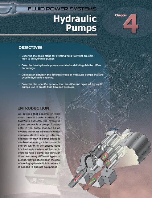
<strong>OBJECTIVES</strong>• Describe the basic steps for creating fluid flow that are commonto all hydraulic pumps.• Describe how hydraulic pumps are rated and distinguish the differentratings.• Distinguish between the different types of hydraulic pumps that areused in hydraulic systems.• Describe the specific actions that the different types of hydraulicpumps use to create fluid flow and pressure.<strong>INTRODUCTION</strong>All devices that accomplish workmust have a power source. Forhydraulic systems, the hydraulicpower source is a pump. A pumpacts in the same manner as anelectric motor. As an electric motorchanges electric energy into mechanicalenergy, a pump changesmechanical energy into hydraulicenergy, which is the energy usedin a hydraulic system. All hydraulicsystems have a pump, and althoughthere are many different types ofpumps, they all accomplish the goalof moving hydraulic fluid to where itis needed to operate equipment.105
106 FLUID POWER SYSTEMSTERMSA hydraulic pump is a mechanicaldevice that changesmechanical energy intohydraulic energy (fluid flow).HYDRAUlic PumpsA hydraulic pump is a mechanical devicethat changes mechanical energy intohydraulic energy (fluid flow). Hydraulicpumps create flow by increasing the volumeof fluid at their inlet and decreasing the volumeof fluid at their outlet. The resistance tofluid flow in the pathway and the load on thesystem create pressure in the system. Thegreater the load or system resistances, thehigher the pressure in the system.Hydraulic pumps are used in all hydraulicsystems and are classified by thetype of pumping mechanisms used. Themain categories of pumps are positivedisplacementand dynamic pumps. SeeFigure 4-1. Although categorized as atype of hydraulic pump, dynamic pumpsare rarely used for hydraulic applicationsbecause they cannot create flow against thepressures found in hydraulic systems.Hydraulic Pump RatingsHydraulic pump ratings are assigned bythe pump manufacturer and are the mainfactors in determining pump use. The mostcommon pump ratings include displacement,gallons per minute, pressure, andvolumetric efficiency.All the information needed to service orreplace a pump can be found on the pumpnameplate. Nameplates are generally affixedto hydraulic pumps to identify the differentpump ratings. In addition to pump ratings, thenameplate also identifies the pump manufacturer’sname, the pump serial number, pumptype, and/or the pump model number.Nameplates are typically made fromstainless steel and affixed to the pumpin an easy-to-read location. The pump’snameplate can sometimes break off, so it isimportant to keep the information in anotherlocation in case the pump fails.Note: Not all hydraulic pumps havenameplates. Relevant pump informationcan also be obtained through the documentsprovided by the manufacturer with thepump’s original packaging. Such informationmust never be discarded but saved forfuture reference.Figure 4-1. The two main types of hydraulic pumps are positive-displacement pumps anddynamic pumps.
Chapter 4 — Hydraulic Pumps 107Displacement. Displacement is the volumeof hydraulic fluid moved during eachrevolution of a pump’s shaft. Displacementis rated in cubic inches per revolution ofthe pump shaft and is calculated by applyingthe following formula:D = rpm × P rwhereD = displacement (in cu in. shaftrevolution)rpm = revolutions per minute of primemoverP r= pump shaft revolutions (in cu in.)Example: What is the displacement of apump with revolutions of 1.94 cu in. thathas a prime mover with revolutions of1120 rpm?Example: What is the gpm of a pump thathas a displacement of 4 cu in. that operatesat 1725 rpm?TERMSDisplacement is thevolume of hydraulic fluidmoved during each revolution,stroke, of a hydraulicpump shaft.A prime mover is a devicethat supplies rotating mechanicalenergy to a fluidpower system.D = rpm × P rD = 1120 × 1.94D = 2173 cu in./minA prime mover is a device that suppliesrotating mechanical energy to a fluid powersystem. The two main types of prime moversused in fluid power systems are electricmotors and internal combustion engines.See Figure 4-2.Gallons Per Minute. When used in fluidpower systems, gallons per minute is thenumber of gallons of fluid that a pumpcan force into the system every minute.Gallons per minute (gpm) is a measureof fluid flow that is used to measure smallvolumes of intermittently flowing fluidssuch as pump discharges. See Figure 4-3.Gallons per minute in a pump is typicallymeasured with a flow meter attached to thehydraulic system, but can be calculatedif certain variables are known. Gpm in apump is calculated by applying the followingformula:displacement × rpmgpm =231wheregpm = gallons per minutedisplacement = cubic inches of flowper revolutionrpm = revolutions per minute231 = constant (cu in. in one gal)Figure 4-2. The two main types of prime movers used in fluid power systemsare electric motors or internal combustion engines.Figure 4-3. Gallons per minute is a measure of fluid flow that is used to measuresmall volumes of intermittently flowing fluids such as pump discharges.
108 FLUID POWER SYSTEMSTERMSGallons per minute (gpm)is a measure of fluid flowthat is used to measuresmall volumes of intermittentlyflowing fluids such aspump discharges.Pressure rating is thehighest amount of pressureat which a pump can createflow against.Volumetric efficiency is therelationship between actualand theoretical fluid flow, orpump gpm.A positive-displacementpump is a pump that hasa positive seal between itsinlet and outlet and moves aspecific volume of hydraulicoil with each revolution ofthe shaft.Pressure Ratings. Pressure rating is thehighest amount of pressure at which a pumpcan create flow against. A pump must bespecified with a higher pressure rating thanthe fluid power system’s maximum pressurerequirement. If a pump’s maximum pressureis not properly rated for the applicationit is used for, the pump will experiencepremature wear and breakdown.Volumetric Efficiency. Volumetric efficiencyis the relationship between actualand theoretical fluid flow, or pump gpm. SeeFigure 4-4. All pumps have internal leakage(slippage). As pressure requirements in afluid power system increase, the efficiencyof the pump decreases. The higher the pumpefficiency, the less internal losses there willbe inside the pump and less energy will belost. Volumetric efficiency is calculated byapplying the following formula:PoEffV= ⎛ ⎞⎝ ⎜ Pro⎠⎟ ×100whereEff V= volumetric efficiency (in %)P o= actual pump output (in gpm)P ro= rated pump output (in gpm)Example: What is the pump efficiency ofa pump rated for 20 gpm that has actualoutput of 19 gpm?PoEffV= ⎛ ⎞⎝ ⎜ Pro⎠⎟ × 100EffV= ⎛ ⎝ ⎜ 19⎞⎠⎟ × 10020EffV= 0.95 × 100Eff = 95%VPositive-Displacement PumpsA positive-displacement pump is a pumpthat has a positive seal between its inletand outlet and moves a specific volumeof hydraulic oil with each revolution ofthe shaft. Positive-displacement pumpsare the only type of pump used in hydraulicsystems and equipment. Typicalapplications for positive-displacementpumps include creating hydraulic flow forhydraulic press equipment, agriculturalequipment, construction equipment, flightnavigation systems, and robotic systems.See Figure 4-5.Figure 4-4. Volumetric efficiency is the relationship between actual and theoretical fluid flowof the pump.
Chapter 4 — Hydraulic Pumps 109Figure 4-5. A typical application for a positive-displacement pump includes the fluid power systems on a hydraulicproduction press.All positive-displacement pumps can operateunder a wide range of pressures, havehigh-pressure capability, can operate in a widerange of environments, and can be small tolarge in size. Positive-displacement pumps aretypically categorized as fixed or variable.Fixed-Displacement Pumps. A fixeddisplacementpump is a positive-displacementpump where the fluid flow rate (gpm) cannotbe changed. Fixed-displacement pumpsare rated by fluid flow, pressure rating, volumetricdisplacement per rotation, maximumpressure rating, minimum and maximumoperating speeds, overall efficiency, noiselevel, mounting options, maximum inputpower (horsepower and kilowatts), torquerange, and fluid cleanliness requirements.Hydraulic fixed-displacement pumps cannotvary the amount of fluid flow that theyproduce during operation without changingthe speed at which they operate.A second method used to change theamount of fluid flow produced by the pumpis to change the pump’s internal components.Typical applications for fixed-displacementpumps include hydraulic systems that do notrequire variation in system pressure, such asmobile hydraulic equipment. See Figure 4-6.Figure 4-6. Fixed-displacement pumps are available in various sizes withdifferent displacement ratings.
110 FLUID POWER SYSTEMSTERMSA fixed-displacementpump is a positivedisplacementpump wherethe fluid flow rate (gpm)cannot be changed.A variable-displacementpump is a positivedisplacementpump thatcan have its flow rate(gpm) changed.Variable-Displacement Pumps. A variabledisplacementpump is a positive-displacementpump that can have its flow rate (gpm)changed. The variable amount of hydraulicfluid that the pump moves is dictated bythe demand of the fluid power system it isinstalled in. A variable-displacement pumpvaries the amount of hydraulic fluid withmovable internal components while the rpmof the prime mover remains fixed.Like fixed-displacement pumps, variabledisplacementpumps are rated by maximumpressure rating, minimum and maximumoperating speeds, overall efficiency, noiselevel, mounting options, maximum inputpower (horsepower and kilowatts), torquerange, and fluid cleanliness requirements.However, unlike fixed-displacement pumps,variable-displacement pumps are also ratedin maximum volumetric displacement perrotation and minimum and maximumpressure compensated ranges. Excessivepressure may cause the pump housing torupture or the pump seals to burst. For maximumsafety, the hydraulic pump selected fora fluid power system must be rated to withstanda pressures that are higher than thehighest anticipated pressure in the system.This prevents damage and possible failureif an overpressure condition occurs. Typicalapplications for variable-displacementpumps include systems that operate withvaried system fluid flow, such as industrialrobotic systems. See Figure 4-7.Figure 4-7. Typical applications for variable-displacement pumps include systems that operate with varied system fluid flow,such as industrial robots.
Chapter 4 — Hydraulic Pumps 111Positive-DisplacementPump OperationAll positive-displacement pumps operatesimilarly to create fluid flow. Therefore, theprinciples of positive-displacement pumpoperation can be applied directly to thedifferent types of positive-displacementpumps encountered in the field. All hydraulicpositive-displacement pumpshave similar parts such as a shaft, pumphousing, inlet port, and outlet port. SeeFigure 4-8. A positive-displacement pumpoperates in four basic steps:1. The pump creates a vacuum by increasingthe volume at its inlet, which is connectedto the reservoir. Vacuum is created in aconfined space that has less pressure thanatmospheric pressure. The vacuum in apump is created when the pump rotatesand an increased volume is created at itsinlet. The pressure in the tank is at atmosphericpressure, which is higher than thevacuum created at the inlet. Atmosphericpressure forces the fluid to flow from thetank into the inlet of the pump.2. Once the fluid enters the pump throughthe inlet, the pump traps the fluidthrough a sealing method. A seal is anairproof and/or fluidproof joint betweentwo members. The fluid travels throughthe pump, in decreasing volume, towardsthe outlet side of the pump.3. Once the trapped fluid moves towardthe outlet side of the pump, the sealedchamber opens and releases the fluid intothe pump outlet.4. The sealed chamber then closes, preventingfluid in the outlet side of thepump from slipping to the inlet side ofthe pump. At the same time, more fluidis forced out of the outlet and into thehydraulic equipment.TECH FACTPositive displacement, as it relates tohydraulic pumps, means that regardless ofthe load or speed involved with a hydraulicsystem, the pump will always displace thesame amount of fluid per shaft revolution.1FLUID FLOWS FROMRESERVOIR TO PUMPFROMRESERVOIRFROMRESERVOIRFROMRESERVOIRPositive-DisplacementPump Operation 4-8PUMP ROTATIONINLET PORTATMOSPHERICPRESSURERESERVOIRHYDRAULICFLUIDTO HYDRAULICEQUIPMENTTO HYDRAULICEQUIPMENTTO HYDRAULICEQUIPMENTTO HYDRAULICEQUIPMENTFigure 4-8. All positive-displacement pumps follow the same basic operationalsteps to create fluid flow.2SEALPOSITIVE-DISPLACEMENTPUMPOUTLET PORTPUMP HOUSINGCHAMBER CAPTURESHYDRAULIC FLUID ANDCARRIES THROUGHPUMP HOUSING34CHAMBER OPENSAND RELEASESHYDRAULIC FLUIDINTO OUTLETCHAMBER CLOSES,PREVENTINGHYDRAULIC FLUIDFROM SLIPPINGBACK TO INLET
112 FLUID POWER SYSTEMSTERMSA seal is an airproof and/orfluidproof joint between twomembers.A gear pump is a hydraulicpump that consists of gearsthat mesh together in variousmanners to create fluid flow.An external gear pump isa gear pump that consistsof two externally toothedgears that form a sealwithin the pump housing.HYDRAULIC PUMP TYPESHydraulic pump types include gear, vane,and piston pumps. All hydraulic pumpscreate fluid flow by following four basicsteps, with some differences accordingto pump type. For example, a gear pumpuses meshing gears to create fluid flow,while a piston pump uses the extensionand retraction of multiple pistons.Gear PumpsA gear pump is a hydraulic pump that consistsof gears that mesh together in variousmanners to create fluid flow. Gear pumpsmay be external, lobe, internal, or gerotorpumps. The teeth on the meshing gearscreate a vacuum at the inlet and then pushthe fluid to the outlet by using a decreasingvolume. See Figure 4-9. Gear pumps areideal for equipment that operates in dirtyenvironments, such as mobile hydraulicconstruction equipment, because a smallamount of dirt in the system will not affectthe overall performance of the pump.Gear pumps consist of two meshing gears enclosed in a close-fitting housing.Figure 4-9. A gear pump consists of varioustypes of meshing gears.
Chapter 4 — Hydraulic Pumps 113All gear pumps are fixed-displacementpumps. The most practical method usedto change the flow of a gear pump is toreplace its meshing gears with those of adifferent size. Each gear pump has specificapplications, and each has advantages anddisadvantages. Advantages of using gearpumps are that they are inexpensive, workwell in dirty environments, are easier torepair than other pumps, can be used with awide range of hydraulic fluid viscosities, areless sensitive to pump cavitation, have lownoise levels, and have an output that is morepredictable because it is linear with the speedof the prime mover.Disadvantages include that they are not asefficient as other types of pumps, have fixedclearance ends, and can only accomplish volumecontrol by changing the pump gears orchanging the speed of the prime mover. Gearpumps can be found in low volume transferapplications such as hydraulic aerial lifts, logsplitters, dump trucks, trailers, earthmovers,trucks, buses, and machine tool equipment.External Gear Pumps. An external gearpump is a gear pump that consists of two externallytoothed gears that form a seal withinthe pump housing. External gear pumps havetwo equal-sized gears, the drive gear anddriven gear, which rotate to cause fluid to flowinto the system. See Figure 4-10. Externalgear pumps operate in four basic steps:1. As the drive gear rotates, it turns the drivengear. This causes both gears to move awayfrom the inlet. This movement creates avacuum on the inlet side of the pump asthe gear teeth pull apart. The atmosphericpressure then pushes the fluid from thereservoir into the inlet.2. As both gears rotate away from the inlet,the gear teeth move closer to the pumphousing internal wall. This traps the fluidand forces it between the gear teeth andthe internal wall toward the discharge.3. As the gear teeth reach the outlet, theypull away from the internal wall. Thefluid is then released. As the gear teethstart moving toward each other again,all fluid is forced out of the pump bydecreasing volume.4. As the gear teeth mesh back together, theyform a seal that does not allow most of thefluid to flow back into the inlet. More fluidmoves into the outlet area each time fluidis forced out of the gear teeth. This forcesthe fluid through the outlet port and intothe hydraulic system.Lobe Pumps. A lobe pump is a positivedisplacementpump that has two externaldriven,intermeshing, lobe-shaped gears. Alobe pump operates similar to an externalgear pump. See Figure 4-11. The main advantageof having two driven lobes is that thetwo lobes do not have to make contact witheach other, thereby reducing the amount ofoperational noise and wear on the pump. Alobe pump requires timing gears to drive thelobe-shaped driven gears.Although lobe pumps can be usedin hydraulic applications, they are typicallyused in pneumatic applications orto move products such as slurries, pastes,and solids. Lobe pumps are commonlyused in industries such as pulp and paperprocessing chemical refining, food andbeverage processing, pharmaceutical production,and biotechnology. Lobe pumps operatein four basic steps:1. As the lobes unmesh, they create avacuum by increasing the volume on theinlet side of the pump.2. The fluid flows into the pump housingand is trapped by the lobes as theyrotate.3. The fluid travels around the interiorof the pump housing in the gaps betweenthe lobes and starts to leave thetrapped areas.4. The meshing of the lobes forces the fluidthrough the outlet into the system.TECH FACTCommon external gear pump applicationsinclude pumping acids, fuels, andlube oils; metering chemical additives andpolymers; mixing and blending chemicals;transferring low-volume fluid; andoperating industrial and mobile hydraulicequipment, such as log splitters.TERMSA lobe pump is a positivedisplacementpump that hastwo external-driven, intermeshing,lobe-shaped gears.An internal gear pump is agear pump that consists ofa small external drive gearmounted inside a large internalspur gear, also called aring gear.A crescent seal is a crescent-moon-shapedseal betweenthe gears and betweenthe inlet and outlet sides ofan internal gear pump.
114 FLUID POWER SYSTEMSFigure 4-10. An external gear pump consists of meshing gears that form a seal with the pump housing and operates similarto the four basic steps of a positive-displacement pump.Figure 4-11. A lobe pump has two external driven gears and operates similar to an external gear pump.
Chapter 4 — Hydraulic Pumps 115Internal Gear Pumps. An internal gearpump is a gear pump that consists of asmall external drive gear mounted insidea large internal spur gear, (ring gear). Thetwo gears rotate in the same direction. SeeFigure 4-12. A crescent seal separates thelow- and high-pressure areas of the pump.A crescent seal is a crescent-moon-shapedseal between the gears and between theinlet and outlet sides of an internal gearpump. Hydraulic fluid is trapped as thegears rotate and is discharged through thepump outlet.Internal gear pumps can pump fluids witha wide range of viscosity and can operate attemperatures up to 750°F. Because there areonly two moving parts, internal gear pumpsare reliable and easy to maintain. Internalgear pumps are typically used in industrialproduction facilities. Internal gear pumpsoperate in three basic steps:1. As the motor turns the externaltoothed gear, the gear teeth unmesh,creating an increasing volume. Atmosphericpressure then pushes the fluidfrom the reservoir into the inlet of thepump.2. The fluid becomes trapped in the cavitiesof the unmeshed gears. As the gearsrotate, the crescent seal separates theinternal gear and the external gear. Thefluid continues to move as the two gearscontinue to rotate.3. As the two gears reach the end of thecrescent seal, the gears begin to meshagain, decreasing the volume. Thedecrease in volume forces the fluid outof the cavities between the teeth andcauses the fluid to flow through theoutlet side of the pump and into thehydraulic system.FLUID FROMRESERVOIR2INLETFLUIDInternal Gear Pump Operation 4 -12OUTLETDIRECTIONOF ROTATION1FLUID BECOMES TRAPPEDBETWEEN UNMESHEDGEAR CAVITIESFLUIDTOHYDRAULICEQUIPMENTINTERNAL GEAR TEETH PULLAWAY FROM EXTERNAL GEARTEETH, CREATING VACUUM3INTERNAL GEARHOUSINGEXTERNAL GEARCRESCENTSEALCRESCENT SEALCREATESSEAL BETWEENBOTH GEARSAS GEARS MESH TOGETHER,FLUID IS FORCED THROUGHOUTLET SIDE OF PUMPEND OFCRESCENT SEALTECH FACTIn addition to hydraulic oil, internal gearpumps are used to pump fuel oil, lubeoil, resins, polymers, alcohols, solvents,asphalt, bitumen, tar, polyurethanefoam, products, paint, inks, pigments,soaps, surfactants, and glycol.Figure 4-12. An internal gear pump consists of a small external drive gearmounted inside a large internal gear.
116 FLUID POWER SYSTEMSTERMSA gerotor pump is a gearpump that has an inner rotorthat meshes with the gearteeth of an outer rotor.Gerotor Pumps. A gerotor pump is a gearpump that has an inner rotor that mesheswith the gear teeth of an outer rotor. Theinner rotor has one less gear tooth than theouter rotor and both rotors rotate in the samedirection. Gerotor pump operation is similarto internal gear pump operation without thecrescent seal. See Figure 4-13.Gerotor pumps are used for low- tomoderate-pressure hydraulic applicationsof less than 1000 psi, such as trashcompactors, hydraulic lifts, and hydraulicelevators. Because gerotor pumps aresusceptible to problems with dirt, theycan only be used in applications thathave clean oil. Due to these considerations,gerotor pumps are used in clean,low-pressure industrial and commercialapplications. Gerotor pumps operate inthree basic steps:1. Fluid enters the inlet port between theinner rotor and outer rotor.2. Fluid travels through the pump betweenthe teeth of the two rotors.3. The inner rotor and outer rotor teethmesh to form a seal between the inletand outlet ports, forcing the fluidthrough the outlet port.Figure 4-13. Gerotor pump operation is similar to internal gear pump operation,with the inner rotor having one less gear tooth than the outer rotor.Gear Pump AssemblyGear pumps can sometimes be repaired inthe field. For a technician to accomplishthis, they must have an understanding ofhow the pump is assembled. Gear pumpassemblies consist of major parts (a frame,gears, housing, and a shaft) and minorparts (O-rings, backup rings, and seals)that may need to be repaired, replaced, orrefurbished. Many gear pump manufacturerssupply step-by-step procedures for theassembly and disassembly of their pumps.This allows a technician to repair a gearpump in the field, rather than removing itfrom the hydraulic equipment and sendingit out for repair. Gear pump manufacturersalso supply part numbers and/or descriptionsfor every part that may need to bereplaced. See Figure 4-14.For example, the two gears in a gearpump can be replaced by applying the followingprocedure:1. Remove the pump from its motor couplingby removing the bolts.2. Remove all bolts from the front of thepump that hold the pump assemblytogether.
Chapter 4 — Hydraulic Pumps 117Figure 4-14. Gear pump manufacturers typically provide assembly diagrams for each specific pump.3. Disassemble pump.a. Detach the front plate assembly fromthe pump.b. Remove the two gears from the bodyhousing.c. Detach the body housing from theback plate assembly.4. Place all parts in a straight line in the exactorder that they were disassembled.5. Inspect all seals that connect the threemain sections together.a. If the seals are good, proceed to step6.b. If the seals are worn or damaged,replace them.6. Inspect the ball bearings for wear andlubrication. Replace or regrease as required.7. Replace the two gears with new gears inthe order that they have been laid out.8. Reassemble the gear pump by workingbackwards from step 7.that expand and retract from the rotor whilemoving the fluid toward the output. SeeFigure 4-15. There are a number of differenttypes of vane pumps including unbalancedvane pumps; variable-displacement,pressure-compensated vane pumps; andbalanced vane pumps.TERMSA vane pump is a hydraulicpump that creates a vacuumby rotating a rotor inside acam ring while trapping fluidbetween vanes that extendand retract from the rotorwhile moving the fluid towardthe output.An unbalanced vane pumpis a fixed- or variable-displacementhydraulic pump inwhich the pumping action occursin the chambers on oneside of the rotor and shaft.Vane PumpsA vane pump is a hydraulic pump that createsa vacuum by rotating a rotor inside acam ring while trapping fluid between vanesFigure 4-15. A vane pump contains vanes inan offset rotor and rotates the rotor to producethe flow of hydraulic fluid.
118 FLUID POWER SYSTEMSEach type of vane pump follows fourbasic operational steps. However, all vanepumps have similar parts such as the shaft,cam ring, vanes, rotor, inlet port, outlet port,and pump body.Vane pumps are known for their drypriming capability, ease of maintenance,and good suction characteristics over thelife of the pump. Because of a smoother,nonpulsing flow rate, vane pumps runquietly and efficiently. Vane pumps canoperate at temperatures ranging from –25°Fto 500°F. Vane pumps extend their vanesthrough centrifugal force or through a mechanicalmeans such as a spring.Unbalanced Vane Pumps. An unbalancedvane pump is a fixed- or variable-displacementhydraulic pump in which the pumpingaction occurs in the chambers on one side ofthe rotor and shaft. Unbalanced vane pumpshave the simplest design of the various typesof vane pumps.An unbalanced vane pump is typicallyused in low-pressure applications. See Figure4-16. A high pressure differentialbetween the inlet and outlet of the pumpcreates a load on the rotor that is attachedto the shaft. Larger bearings and shafts mustbe used because of this extra load, whichlimits the size of unbalanced vane pumps.Unbalanced vane pumps operate in fourbasic steps:1. The offset rotor rotates with vanes contactingthe cam ring, creating a vacuumat the inlet of the pump. As the rotorrotates, the vanes extend outward bycentrifugal force, creating a confinedspace for the fluid. The shape of the inletallows the pump to pull more fluid intothe confined space.2. As the fluid becomes trapped betweenthe vanes and the cam ring, it is forcedtoward the outlet of the pump.3. As the trapped fluid gets closer to theoutlet side of the pump, it is releasedfrom its confined space. The outlet isalso shaped to allow more fluid to movethrough the pump. At this point, thevanes are forced back into the rotor bythe cam ring, making a smaller confinedspace for the fluid.4. As the fluid is forced out of the confinedspace, the rotor and the cam ring providea leakproof seal that does not allow thefluid to slip back to the inlet. At thesame time, more fluid is forced out of thepump, forcing fluid into the system.Figure 4-16. Unbalanced vane pumps operatesimilar to the four basic steps of a positivedisplacementpump.
Chapter 4 — Hydraulic Pumps 119Variable-Displacement, Pressure-Compensated Vane Pumps. A variabledisplacement,pressure-compensated vanepump is a pump that automatically adjuststhe amount of volume it displaces perrotation by centering the rotor when thepressure in the system starts to build. SeeFigure 4-17. A variable-displacement,pressure-compensated vane pump operatesby adjusting a cam ring to allow thevolume per revolution to change accordingto system pressure. This type of pumpprotects itself against excessive pressure byreducing power consumption as the flowrate decreases. When pressure reaches acertain value, the compensator spring forceequals the hydraulic piston force. As pressurecontinues to increase, the compensatorspring is compressed until concentricity onthe compensator ring is achieved. Maximumpressure is then achieved. At this point, thepump is protected because it produces nomore flow, resulting in no power loss and nofluid heating. A thrust block is used to ensuresmooth movement and correct placement ofthe cam ring.Variable-displacement, pressurecompensatedvane pumps are the mostcommonly used vane pumps and haveease of maintenance over the life of thepump. Setting the maximum fluid flowof a variable-displacement, pressurecompensatedvane pump is performedusing the following procedure:1. Connect the outlet side of the pumpdirectly to a pressure gauge.2. Turn the pump ON and record the pressurewhen the pump rotor becomes centered.3. Use the pressure adjustment screw toset the desired fluid flow.TERMSA variable-displacement,pressure-compensatedvane pump is a pumpthat automatically adjuststhe amount of volume itdisplaces per rotation bycentering the rotor when thepressure in the system startsto build.Figure 4-17. A variable-displacement, pressure-compensated vane pump is a pump that automaticallyadjusts the amount of volume it displaces per rotation by centering the rotor whenthe pressure in the system starts to build.
120 FLUID POWER SYSTEMSTERMSA balanced vane pump is apump that consists of a camring, rotor, vanes, and a portplate with opposing inlet andoutlet ports.A cartridge assembly is acartridge located in a vanepump that houses the vanes,rotor, and cam ring, whichare all placed between twoend plates.A piston pump is a hydraulicpump in which fluid flowis produced by reciprocatingpistons.Balanced Vane Pump. A balanced vanepump is a pump that consists of a cam ring,rotor, vanes, and a port plate with opposinginlet and outlet ports. See Figure 4-18.This creates a balanced load on the pumpbearings and seals. The two inlets and twooutlets are set 180° apart from each other.This helps to prolong the life of the shaftbearings and allows the pump to run athigher speeds and at higher pressure ratingsthan an unbalanced vane pump. A balancedvane pump also has an elliptical cam ring.Figure 4-18. A balanced vane pump has two inlets and outlets at oppositesides of the pump and contains an elliptical cam ring.A cartridge assembly is a cartridgelocated in a vane pump that houses thevanes, rotor, and cam ring, which are allplaced between two end plates. See Figure4-19. A cartridge assembly allows atechnician to service the pump quicklybecause it allows for replacement of theentire assembly when the internal partsneed to be replaced. Additionally, changingthe size of the cartridge assembly canchange the displacement of the pump.Vane Pump AssemblyLike gear pumps, many types of vanepumps can be repaired in the field. Vanepump assemblies are more complicatedthan gear pump assemblies and requiremore time to repair. Many manufacturersprovide detailed assembly and disassemblyinstructions for vane pumps that makeit possible to repair, replace, or refurbishany part of a vane pump. It is also commonfor vane pump assemblies to haverebuild kits that can be ordered and keptonsite for quicker repair time. Usuallyspecific assembly and disassembly instructionsare used because vane pumpsmay have a cartridge that holds the vanes.See Figure 4-20.Figure 4-19. A cartridge assembly is located in a vane pump and houses the vanes, rotor, andcam ring, which are all placed between two plates.
Chapter 4 — Hydraulic Pumps 121Figure 4-20. Vane pump manufacturers typically provide assembly diagrams for each specific pump.For example, a cam ring in a vane pumpis replaced by applying the followingprocedure:1. Remove the pump from its foot bracketby removing the bolts.2. Remove four bolts from the back of thepump.3. Disassemble the pump into three sections.a. One section is the back housing withO-rings.b. Another section is the cartridge assembly.c. The third section is the front housingwith the shaft.4. Place all parts in a straight line in the exactorder that they were disassembled.5. Inspect all the seals that connect thethree main sections together.a. If the seals are good, go to step 6.b. If the seals are worn or damaged,replace them.6. Inspect the ball bearings for wear andlubrication. Replace or regrease asrequired.7. Remove two screws holding the vanecartridge together.8. Place all parts from the vane cartridgein a straight line in the exact order thatthey were disassembled.9. Remove the cam ring and the rotor,making sure that the vanes do not fallout of the rotor.10. Remove all vanes from the rotor andinspect for premature wear.11. Replace the damaged cam ring with anew cam ring.12. Reassemble the vane pump by workingbackwards from step 11.Piston PumpsA piston pump is a hydraulic pump in whichfluid flow is produced by reciprocatingpistons. Piston pumps are either fixed orvariable displacement. They use a rotatinginternal piston assembly to create a vacuumas the pistons pull away from the inlet. Thepiston assembly then forces fluid out whenthe pistons are pushed toward the outlet.A bent-axis piston pump is the mostdurable type of hydraulic pump and canoperate at pressures of up to 10,000 psi.Piston pumps are typically used in applicationssuch as small loaders. Types of pistonpumps include axial, variable-displacement,bent-axis, and radial piston pumps.TECH FACTTo achieve a uniform volumetric flowrate of hydraulic fluid, hydraulic pistonmachines, such as piston pumps, aredesigned with an odd number of pistons.For example, many hydraulic pistonpumps are designed to house seven ornine pistons.
122 FLUID POWER SYSTEMSTERMSAn axial piston pump is apiston pump that consists ofpistons in a rotating pistonblock parallel to the driveshaft.A swash plate is an angledplate in contact with thepiston heads that moves thepistons in the cylinders of apump.A variable-displacementpiston pump is a pistonpump in which the angleof the swash plate can bevaried.Axial Piston Pumps. An axial piston pumpis a piston pump that consists of pistons ina rotating piston block parallel to the driveshaft. Axial piston pumps create smooth fluidflow for piston pumps. See Figure 4-21.Axial piston pumps consist of a numberof pistons, a piston block, piston shoes, aswash plate, and a drive shaft. A swash plateis an angled plate in contact with the pistonheads that causes the pistons in the cylindersof a pump to extend and retract. Typicalapplications for piston pumps include highpressuredevices, such as large press machines,and heavy-duty construction andindustrial equipment. Axial piston pumpsoperate in four basic steps:1. As the drive shaft rotates, the pistonblock rotates in the same direction.This pulls a piston from the numberof pistons out and creates suction. Thepiston is pulled because it is attached tothe swash plate and the swash plate isin a fixed, slanted position. The fartherback the piston moves, the more volumeof fluid it will move. The length of thepiston is the main determinant to theamount of gpm a pump can produce.2. As the piston moves through the firsthalf of the pump, it pulls more fluidevery degree it turns, trapping morefluid in the piston barrel.3. When the piston reaches the halfwaypoint of a cycle (180°), the pistonpushes fluid out of the piston barrel. Asthe shaft continues to rotate, more fluidis forced out of the piston barrel.4. As the piston completes a 360° cycle, allfluid is pushed out of the piston barrel,creating a leakproof seal that will notallow the oil to reenter the inlet. At thesame time, the next piston forces fluidout of its barrel, which forces fluid flowin the hydraulic system.Figure 4-21. Axial piston pumps consist of a number of pistons, a piston block, piston shoes, a swash plate, and a shaft andoperate with four basic steps.
Chapter 4 — Hydraulic Pumps 123Hydraulic pumps are used to provide fluid power toconcrete compression testers.Variable-Displacement Piston Pumps. Avariable-displacement piston pump is a pistonpump in which the angle of the swash platecan be varied. See Figure 4-22. Variabledisplacementpiston pumps have a simpledesign. They are also reliable and durable.Variable-displacement piston pumps includeapplications where a large amount of variedpressure is required such as backhoes, hydrauliccranes, heavy-duty presses, and balers.They are also used in applications where heatbuildup can affect pump performance.A variable-displacement piston pumpworks under the same principles as an axialpiston pump with the exception of the variabilityof the angle of the swash plate. Whenthe angle of the swash plate is varied, itchanges the distance of how far back a pistonpulls. This causes the piston to allow more orless fluid into its barrel, varying the amountof gpm that the pump produces.TECH FACTThe pistons in an axial piston pumpreciprocate parallel to the centerline ofthe drive shaft of the piston block. Rotaryshaft motion is converted into axialreciprocating motion. Most axial pistonpumps contain multiple pistons and usecheck valves or port plates to direct fluidflow from the inlet port to the outlet port.Figure 4-22. A variable-displacement piston pump has a swash plate at anangle that can be varied, thereby varying the amount of fluid flow (gpm).
124 FLUID POWER SYSTEMSTERMSA bent-axis piston pump isa piston pump in which thepistons and cylinders are atan angle to the drive shaftand thrust plate.A radial piston pump is apiston pump that consists ofpistons located perpendicularto the pump shaft.The most common method to vary theangle of a swash plate is through internalpilot pressure. As the pressure in the fluidpower system begins to reach the set pressureof the pump, pressure from the internalpilot lines begins to push on the pilot valveattached to the swash plate.Maximum pilot pressure is set with asetscrew that adjusts a control spring. Asthe swash plate begins to move, the distancethe pistons pull back into the barrel changes.When the swash plate is vertical, there is nofluid flow produced by the pump. However,the prime mover still rotates at the samerpm, which saves energy because there isno load on the motor and there is no energybeing wasted as heat from fluid movingthrough the pressure relief valve.Bent-Axis Piston Pumps. A bent-axispiston pump is a piston pump in which thepistons and cylinders are at an angle to thedrive shaft and thrust plate. See Figure 4-23.Bent-axis piston pumps operate similarlyto axial piston pumps, but rather than theswash plate being at an angle (offset), thepistons and piston block are at an angle(offset). The angle at which the pistonsand piston block are offset determines theamount of fluid that each piston can takein. Thus, the angle at which the pistons andpiston block are set determines the amountof fluid flow.Figure 4-23. Bent-axis piston pumps operate in the same manner as an axialpiston pump, but rather than the swash plate being at an angle, the pistonsand piston block are at an angle.Bent-axis piston pumps can be eitherfixed or variable. Fixed bent-axis pistonpumps work by rotation from the primemover that the angled piston is attachedto. As they rotate, the pistons extend andretract, creating fluid flow. Variable bentaxispiston pumps work by adjusting theangle at which the pistons and the pistonblock sit. Typical applications for bent-axispiston pumps include mobile and industrialequipment where a high-pressure rating isrequired and space is limited.Radial Piston Pumps. A radial pistonpump is a piston pump that consists of acylinder barrel, pistons with shoes, a ring,and a valve block located perpendicular tothe pump shaft. See Figure 4-24. Radialpiston pumps are high-pressure hydraulicpumps, capable of operating at 10,000 psi.Radial piston pumps are used becauseof the design of their pistons and barrel,which allow for a short stroke. Typicalapplications for radial piston pumps includeequipment that uses a heavy fluidfor low fluid flow and high pressure, suchas plastics injection molding machines ordie-casting machines for metals.Radial piston pumps are classified ascam or rotating piston pumps. In a campump, a rotating internal cam moves thepistons in cylinders. The cam is shapedto push the pistons out during one halfof the cam rotation and allow the pistonsto retract during the other half. There arealso variable pressure-compensated radialpiston pumps.A variable pressure-compensated radialpiston pump works similar to a variableaxial model by adjusting the stroke of thepistons to adjust the amount of fluid flowas pressure increases. The amount of fluidflow is adjusted by centering the cam ringand controlling the distance that the pistonsextend and retract. In a rotating pistonpump, pistons are housed in a rotatingpiston block that is offset inside the pumphousing and rotates around a fixed shaft.Fluid enters the pump inlet as the pistonsextend and is discharged from the pumpoutlet as the pistons retract.
Chapter 4 — Hydraulic Pumps 125Cavitation. Cavitation is a localized gaseouscondition within a stream of fluid,which occurs when pressure is reducedto vapor pressure. Implosion is an inwardbursting. See Figure 4-25. Pseudocavitationis artificial cavitation caused by air beingallowed into the pump suction line. Pseudocavitationis caused by low reservoir fluid,contaminated fluid, or leaking pump suctionlines. Pseudocavitation is indicated by a loudnoise for an extended period of time.TERMSCavitation is a localizedgaseous condition within astream of fluid, which occurswhen pressure is reduced tovapor pressure.Implosion is an inwardbursting.Pseudocavitation is artificialcavitation caused by airbeing allowed into the pumpsuction line.Figure 4-25. Cavitation occurs as gas bubbles expand in a vacuum andimplode when entering a pressurized area.Figure 4-24. Radial piston pumps consist ofreciprocating pistons in cylinders and can beclassified as cam or rotating piston pumps.Radial piston pumps operate on thesame basic principles as axial pistonpumps but are built with the pistons lyingflat and facing inward toward the shaft.The inlet and outlet are located close tothe shaft, and the piston block is off-centerinside the cam ring. As the shaft rotates,the pistons extend and retract to completethe four basic operational steps of positivedisplacementpumps.Pseudocavitation occurs when the inletport of a pump is restricted. An indicationof pump cavitation is a high shrieking soundor a sound similar to loose marbles or ballbearings in the pump. Pseudocavitation isnormally created when the suction line isdamaged, plugged, or collapsed. Pseudocavitationmay also be caused by an increasein pump rpm that requires more fluid thanthe system piping allows, fluids with anincreased viscosity due to lower ambienttemperatures, or an increase in the viscosityof a fluid in a system when the system hasa long suction line.TECH FACTNot allowing air to dissolve in hydraulicfluid helps prevent pump cavitation. Aircan be removed most effectively whenfluid is in the tank. It takes time for airto separate from fluid, so the path fromthe tank return line to the pump inletmust be as long as possible and with aslittle turbulence present as possible.
126 FLUID POWER SYSTEMSWith cavitation, as the pump pulls againsta fluid that does not flow, a greater vacuumis created. Any microscopic air or gas withinthe fluid expands. Expanded bubbles on theinlet side collapse rapidly on the outlet sideof the pump. The small but tremendousimplosions can cause extensive damage topump parts. Theoretically, an air bubble exposedto a 5000 psi cavitation may create animplosion pressure of 75,000 psi and travelat a speed of 600 fps to 4000 fps.Double and Triple PumpsAlthough rare in modern hydraulic equipment,hydraulic pumps are available withdouble and triple pump styles. These pumpstyles have two or three pumping unitsinside a single pump housing on the sameshaft. The pumping units may or may notbe the same size. The advantage of thesesystems is that one prime mover is usedto rotate two or three pumps at the sametime. Double and triple pumps can providegreater flow by connecting the pumpsin series or they can supply two or threedifferent hydraulic systems using only oneprime mover. Each pump requires its ownrelief valve. Only one pump unit needs tobe installed when using double or triplepumps, which simplifies the installationprocess. Pumps that are connected togethercan deliver greater volumes of hydraulicfluid and produce higher pressures than asingle pump.In addition to high cost, the main disadvantageof using double or triple pumpsis that if one of the pump units breaksdown, the entire hydraulic system mustbe shutdown while the pump is repaired.Double and triple pumps are used inmobile and industrial applications suchas hydraulic log splitters, shear presses,underground well drilling machines,and trash compactors. For example, asmall pump can provide hydraulic fluidto a piece of equipment while the largerpump can unload fluid to the reservoir.The most common types of double andtriple pumps are gear and vane pumps.See Figure 4-26.Figure 4-26. Hydraulic pumps are available in both double and triple pump designs.
Chapter 4 — Hydraulic Pumps 127Hydraulic PumpSchematic SymbolsHydraulic pump schematic symbols are usedto determine general information about thepump used in a system. See Figure 4-27.While hydraulic pump schematic symbols donot provide direct information on pump type,such as piston, gear, or vane, they do provideinformation on whether the pump is unidirectionalor bidirectional by using arrows.These symbols also provide information onwhether the pump is fixed or variable.Figure 4-27. Hydraulic pump schematic symbols are used to determine general information about the type of pump usedin a system.Quick Quiz ®Refer to CD-ROM for the Quick Quiz ® questions related to chapter content.
128 FLUID POWER SYSTEMS
Chapter 4 — Hydraulic Pumps 129MULTIPLE CHOICE1. Fixed-displacement pumps are rated by fluid flow and ___.A. electrical requirementsB. housing sizeC. pressure ratingD. speed2. Hydraulic pump types include gear, vane, and ___ pumps.A. centrifugalB. gerotorC. lobeD. piston3. ___ is a localized gaseous condition within a stream of fluid that occurs when pressureis reduced to vapor pressure.A. CavitationB. ImplosionC. PseudocavitationD. all of the above4. A lobe pump requires ___ to drive the lobe-shaped driven gears.A. lobe gearsB. pistonsC. timing beltsD. timing gears5. ___ is the volume of hydraulic fluid moved during each revolution of the shaft ofa pump.A. DisplacementB. Gallons per minuteC. Revolutions per minuteD. Volumetric efficiency6. A ___ pump has an inner rotor that meshes with the gear teeth of an outer rotor.A. gerotorB. lobeC. pistonD. vane7. A variable-displacement pump varies the amount of hydraulic fluid with movableinternal components while the ___ of the prime mover remains fixed.A. displacementB. gpmC. rpmD. volumetric efficiency
130 FLUID POWER SYSTEMS8. Bent-axis piston pumps are different from axial piston pumps because their ___ are atan angle (offset).A. pistons and piston blockB. swash platesC. pistons, piston block, and swash plateD. none of the above9. A(n) ___ plate is an angled plate used to extend and retract the pistons in an axial pistonpump.A. axialB. cylinder barrelC. pistonD. swash10. The main categories of hydraulic pumps are dynamic and ___ pumps.A. fixedB. nonpositive-displacementC. positive-displacementD. variable11. The most common method to vary the angle of a swash plate is through ___.A. internal pilot pressureB. the speed of the prime moverC. the rotating vanesD. the cartridge assembly12. A ___ is part of a vane pump and houses the vanes, rotor, and cam ring, which are allplaced between two end plates.A. cam ringB. cartridge assemblyC. cartridge fittingD. slotted rotor13. Gear pumps may be external, internal, lobe, or ___.A. centrifugalB. gerotorC. pistonD. vane14. ___ is the highest amount of pressure at which a pump can create fluid flow.A. DisplacementB. Gallons per minuteC. Pressure ratingD. Volumetric efficiency15. A(n) ___ vane pump allows adjustment of the flow rate of the pump.A. axialB. balancedC. variable-displacementD. variable-displacement, pressure-compensated
Chapter 4 — Hydraulic Pumps 131COMPLETION1. A(n) ___ is an airproof and/or fluidproof joint between two members.2. Vane pump types include unbalanced, balanced, and ___.3. A(n) ___ is a crescent-moon-shaped seal between the gears and between the inlet andoutlet sides of an internal gear pump.4. A(n) ___ pump has pistons in a rotating cylinder block parallel to the drive shaft.5. A(n) ___ piston pump has pistons and cylinders that are at an angle to the drive shaftand thrust plate.6. A(n) ___ allows a technician to replace an entire assembly in a vane pump when theinternal parts need to be replaced.7. ___ is the relationship between actual and theoretical fluid flow.8. Pseudocavitation is caused by ___ being allowed into the suction line.9. ___ are generally affixed to a pump to identify the different pump ratings.10. A(n) ___ vane pump is a fixed- or variable-displacement hydraulic pump in which thepumping action occurs in the chambers on one side of the rotor and shaft.11. A(n) ___-displacement piston pump can have the angle of its swash plate varied.12. A(n) ___ pump uses gears that mesh together in various manners in a close-fittinghousing to create fluid flow.13. A(n) ___-displacement pump cannot have its fluid flow (gpm) changed.14. ___ pumps are known for their dry priming capability, ease of maintenance, and goodsuction characteristics over the life of the pump.15. A(n) ___ consists of a cam ring, rotor, vanes, and a port plate with opposing inlet andoutlet ports set 180˚ apart from each other.16. ___ is the volume of hydraulic fluid moved during each revolution of the shaft of apump.17. A(n) ___ is a mechanical device that changes mechanical energy into hydraulic energy(fluid flow).18. A(n) ___ piston pump has pistons located perpendicular to the pump shaft.19. Pseudocavitation occurs when the ___ port of a pump is restricted.20. A(n) ___ pump has a positive seal between its inlet and outlet and moves a specificvolume of hydraulic fluid with each revolution of the shaft.
132 FLUID POWER SYSTEMSTRUE/FALSET F 1. Although lobe pumps can be used in pneumatic applications, they are typically usedin hydraulic applications to move products such as slurries, pastes, and solids.T F 2. Hydraulic fixed-displacement pumps cannot vary the amount of fluid flow that theyproduce during operation without changing the speed at which they operate.T F 3. External gear pumps have two different size gears.T F 4. A balanced vane pump has an elliptical cam ring.T F 5. Displacement is the fluid flow that a pump can produce.T F 6. Axial piston pumps create smooth fluid flow for piston pumps.T F 7. Changing the angle of the swash plate in a variable-displacement piston pump does notaffect the distance of how far back a piston pulls.T F 8. Gear pumps operate through the extension and retraction of multiple pistons.T F 9. All bent-axis piston pumps are variable.T F 10. Dynamic pumps include gear, vane, and piston pumps.T F 11. Pseudocavitation can be caused by low reservoir fluid.T F 12. Gear pumps have the highest level of loudness while in operation.T F 13. Hydraulic pump schematic symbols provide direct information on pump type.T F 14. Vane pumps are typically used in applications that require the movement of high-viscosityfluids.T F 15. A radial piston pump consists of pistons located parallel to the pump shaft.T F 16. Radial piston pumps can be classified as cam or rotating piston pumps.T F 17. All hydraulic pumps have nameplates affixed to them.T F 18. The length of the piston is the main determinant to the amount of gpm that an axialpiston pump can produce.T F 19. Gear pumps are ideal for equipment that operates in dirty environments.T F 20. A bent-axis piston pump can operate at pressures above 10,000 psi.T F 21. The rotor of a variable-displacement, pressure-compensated, vane pump is centeredwith a crescent seal.T F 22. All gear pumps are fixed-displacement pumps.T F 23. Unbalanced vane pumps have the simplest design of the various types of vane pumps.T F 24. Gerotor pumps are used for high-pressure applications of greater than 1000 psi.T F 25. Positive-displacement pumps are typically classified as fixed or variable.
Chapter 4 — Hydraulic Pumps 133MATCHINGCartridge AssembliesABCDE1. Back end plate___2. Cam ring3. Front end plate4. Slotted rotor5. VaneSchematic Symbols1. Hydraulic pump—bidirectional flow—fixed-displacement2. Hydraulic pump—bidirectional flow with case drain—variable-displacement3. Electric motor4. Double-acting cylinder5. Hydraulic pump, unidirectional flow6. Internal combustion engine7. Hydraulic pump—unidirectional flow—fixed-displacement8. Hydraulic pump—unidirectional flow with case drain—variable-displacement9. Hydraulic pump—unidirectional flow with case drain—variable-displacement, pressurecompensated
134 FLUID POWER SYSTEMSGear PumpsA B C D1. External2. Gerotor3. Internal4. LobeBalanced Vane Pumps1. Elliptical cam ring2. Port plate3. Port plate inlet portHA4. Port plate outlet port5. Pump housing inlet portGB6. Pump housing outlet port7. Rotor8. VaneFEDCSHORT ANSWER1. List and describe the four main pump ratings.
Chapter 4 — Hydraulic Pumps 135Activity 4-1: Pump Identification InformationA technician must be able to use a pump nameplate to identify the specific information of different pump parts. Thehydraulic pump on a mobile hydraulic system has failed. The company that manufactured the pump no longer exists,but the original operator’s manual is available.1. List the pump description required for ordering a replacement pump for the existing pump GE-PP-F-CC-07-KY-A2-T.
136 FLUID POWER SYSTEMSActivity 4-2: Vane Pump RepairA vane pump used in a hydraulic press has failed. The rotor has been damaged from contaminated hydraulic fluidand must be replaced.1. Using the parts assembly diagram, list the steps required to disassemble the pump and replace the damaged rotor.
Chapter 4 — Hydraulic Pumps 137Activity 4-3: Vane Pump Cartridge AnalysisBelow is a chart for two vane pump cartridges commonly used in industrial applications. Both vane pumps were testedto see how much fluid flow each produced at specific pressures under standard conditions. The standard conditionsfor both vane pump cartridges are 150 Saybolt Universal Seconds (SUS) hydraulic fluid at 120°F.Use the Vane Pump Cartridge Analysis chart and information from the chapter to answer the following questions:1. If the pump with cartridge A installed is operating at 1000 psi and the prime mover is rotatingat 1200 rpm, what should a flow meter read if installed within 6′ of the pump discharge?2. If the pump with cartridge A installed is operating at 2300 psi and the prime mover is turningat 1700 rpm, what should a flow meter read if installed within 6′ of the pump discharge?3. If the pump with cartridge B installed is operating at 2000 psi and the prime mover is rotatingat 1100 rpm, what should a flow meter read if installed within 6′ of the pump discharge?4. If the pump with cartridge B installed is operating at 3000 psi and the prime mover is rotatingat 1400 rpm, what should a flow meter read if installed within 6′ of the pump discharge?5. If the pump with cartridge A installed is operating at 1000 psi, the prime mover is rotatingat 1700 rpm, and the flow meter reads 13.5 gpm, what is the volumetric efficiency ofthe pump?6. The pump with cartridge A installed is operating at 2300 psi, the prime mover is rotatingat 1600 rpm, and the cartridge is 2.01 cu in. Place a mark on the chart where that shouldbe represented.
138 FLUID POWER SYSTEMSActivity 4-4: Pump AnalysisRefer to Hydraulic System to answer the following questions.1. The pump displacement in Hydraulic System is rated at 2.56 cu. in. and is rotating at1200 rpm. If flow meter FM1 shows a reading of 12.25 gpm, what is the pump efficiencyof the pump to FM1?2. The pump displacement in Hydraulic System is rated at 1.34 cu. in. and is rotating at1000 rpm. If flow meter FM2 shows a reading 5.2 gpm what is the pump efficiency ofthe pump to FM2?3. The pump displacement in Hydraulic System is rated at 1.34 cu. in. and is rotating at1000 rpm. If flow meter FM3 shows a reading 4.2 gpm what is the pump efficiency ofthe pump to FM3?4. What is the difference in pump efficiency between FM2 and FM3?5. List at least two possible reasons for the difference in flow from FM2 and FM3.
Chapter 4 — Hydraulic Pumps 1396. The technician responsible for inspecting Hydraulic System notices that the pump efficiency is down 12% at eachflow meter. List at least five possible reasons for lower pump efficiency. Note: Assume that the system could possiblybe damaged.
140 FLUID POWER SYSTEMSActivity 4-5: Pump Flow RateA hydraulic press needs to have the flow rate of its pump adjusted from 0.45 gpm to 4.98 gpm. Review the schematicdiagram from Hydraulic Press System.1. Use FluidSIM ® to build the same schematic diagram to have a flow rate of 0.45 gpm from the pump and observethe system operation.2. Use FluidSIM ® to build the same schematic diagram to have a flow rate of 4.98 gpm from the pump and observethe system operation.3. What was the outcome of changing the flow rate of the pump?4. List two different methods for changing the flow rate of a pump.