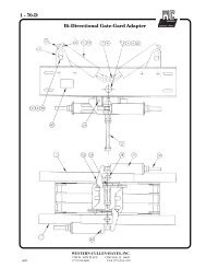
Model 3597 Exit Gate - Western-Cullen-Hayes Inc.
Model 3597 Exit Gate - Western-Cullen-Hayes Inc.
Model 3597 Exit Gate - Western-Cullen-Hayes Inc.
- No tags were found...

You also want an ePaper? Increase the reach of your titles
YUMPU automatically turns print PDFs into web optimized ePapers that Google loves.
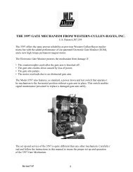
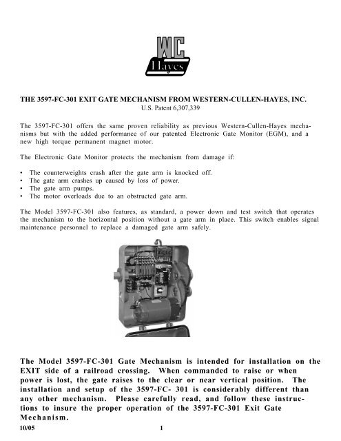
THE <strong>3597</strong>-FC-301 EXIT GATE MECHANISM FROM WESTERN-CULLEN-HAYES, INC.U.S. Patent 6,307,339The <strong>3597</strong>-FC-301 offers the same proven reliability as previous <strong>Western</strong>-<strong>Cullen</strong>-<strong>Hayes</strong> mechanismsbut with the added performance of our patented Electronic <strong>Gate</strong> Monitor (EGM), and anew high torque permanent magnet motor.The Electronic <strong>Gate</strong> Monitor protects the mechanism from damage if:• The counterweights crash after the gate arm is knocked off.• The gate arm crashes up caused by loss of power.• The gate arm pumps.• The motor overloads due to an obstructed gate arm.The <strong>Model</strong> <strong>3597</strong>-FC-301 also features, as standard, a power down and test switch that operatesthe mechanism to the horizontal position without a gate arm in place. This switch enables signalmaintenance personnel to replace a damaged gate arm safely.The <strong>Model</strong> <strong>3597</strong>-FC-301 <strong>Gate</strong> Mechanism is intended for installation on theEXIT side of a railroad crossing. When commanded to raise or whenpower is lost, the gate raises to the clear or near vertical position. Theinstallation and setup of the <strong>3597</strong>-FC- 301 is considerably different thanany other mechanism. Please carefully read, and follow these instructionsto insure the proper operation of the <strong>3597</strong>-FC-301 <strong>Exit</strong> <strong>Gate</strong>Mechanism.10/05 1
The blue wire lead is connected to relay 2MCR. This wire provides the path of voltage to resetthe EGM. The reset signal is sent to the EGM each time a gate clear command is received fromthe control case and during normal gate up operation. A fault condition can also be reset by thepush-button located on the EGM.Normal <strong>3597</strong> <strong>Gate</strong> Mechanism Operation:Mechanism operating voltage is 12 vdc nominal. Static voltage is not to exceed 17 vdc. Voltageat the circuit controller terminals should not drop below 11 vdc during normal operations. Positivevoltage is applied to terminal 6A and negative is applied to terminal 7A on the circuit board.Mechanism control voltage is connected to terminal 5A on the circuit board. To lower the gate,the crossing control system gate relay (XGR) must de-energize, or drop. To raise the gate, theXGR must energize, or pick.Manual Electric <strong>Gate</strong> UP Operation:When a gate down command is present and the gate is in the horizontal position, the gate can beraised by operating the cam switch to the test position. When the cam switch is operated to therun position, and the reset button on the EGM is depressed, the gate will operate to horizontal.This operation is also a test of the EGM.EGM Controlled and Fault Operations of the <strong>3597</strong>-FC-301 <strong>Gate</strong> Mechanism:<strong>Gate</strong> Arm Knocked-Off Operation:If the gate arm is knocked off in the horizontal position, and the gate down command is present,the mechanism counterweight assembly should remain in the horizontal position. That is becausethe motor brake is applied. If the gate arm is knocked off in any position except the fullhorizontal position, the force of gravity could pull the counterweights violently downward.If this condition occurs, the EGM senses a sharp increase in voltage being generated by theforced rotation of the motor. The relays in the EGM de-energize, the green LED will go dark anddynamic breaking controls the decent of the weights and protects against damage to the mechanism.The dynamic braking is accomplished by shorting the A and B terminals of the motorthrough an adjustable resistor.Open Electrical Circuit Failure:The gate mechanism could display the operational characteristics of the gate arm being knockedoff if an open failure in the mechanism electrical circuit were to occur, such as a relay contact notmaking contact, an open resistor or an open condition in the wiring. When such an event happens,the EGM will control the fault the same as described for the knock-off operation providedthe EGM is connected and there are not any opens in the EGM circuit, the shorting resistor orthe motor. Supply power does not have to be present at the EGM for it to control a fault.Horizontal <strong>Gate</strong> Arm Pumping Operation:If a mechanical or electrical failure of the motor brake occurs, the gate arm will oscillate (pump)in the horizontal position. When this happens, the motor powers the gate until the #1F powerdown contact opens. If the gate cannot be mechanically held in the horizontal position, the forceof gravity causes the arm to begin to rise, the #1F contact closes, power is applied to the motorand the gate is driven back to horizontal. This series of events continuously repeats. Each timea pulse of voltage is received at the motor a certain amount of voltage is stored within the EGM.10/05 3
When the stored voltage reaches a threshold, the EGM de-energizes it's relays, the green LEDgoes dark, the pumping ceases and the gate arm rises to vertical position through the controlleddynamic breaking circuit. The gate arm will remain in the vertical position until the EGM receivesa pulse of 12 vdc positive voltage at the reset wire lead. This is created by a gate up commandsent from the external crossing control system, or the manual reset button located on theEGM is depressed. When reset, the green LED illuminates.<strong>Gate</strong> Hang-up / Obstruction Failure Operation:If the gate arm becomes obstructed while power is applied to the motor, after a period of time theEGM will de-energize it's relay to prevent electrical component burn-up. When power is appliedto the motor, a certain amount of the voltage is stored within the EGM. When the stored voltagereaches a threshold, the EGM de-energizes it's relays, the green LED goes dark and power isremoved from the motor. When the EGM removes motor power the gate will rise to the nearvertical position and float free as the motor brake is not applied. When the gate up command isreceived, the EGM will reset. If the gate has come to a rest at a point greater than 60 degreesbut less than 75 degrees, the motor will start and power the gate to the full vertical position. Ifthe gate has come to rest at a point greater than 75 degrees, it will free float. The next gatedown command will lower the gate. The next gate up command will cause the gate to rise andlatch in the full vertical position, provided the obstruction mode has not repeated its operation.EGM Operation Annunciation:The EGM annunciation relay connection should not be used as the normal gate up operation ofthe <strong>3597</strong>-FC-301 causes the EGM to trip every time the gate is commanded to rise.<strong>3597</strong>-FC-301 <strong>Gate</strong> Mechanism Arm Service Operation:<strong>Gate</strong> Arm Service (Power Down) Mode:To lower the gate counterweight assembly (raise weights), control the gate down with the crossingsystem controls. The motor brake will hold the mechanism in the horizontal position for gatearm service. Another method of raising the counterweights is outlined below:The <strong>3597</strong>-FC-301 incorporates a three position cam switch for this purpose. In the run position,the gate operates normally and the EGM is connected into the circuit. In the test position, thecircuitry is disconnected from the motor and the EGM is connected to the circuit. In the downposition, full power down is applied to the motor to drive the counterweights to the horizontalposition. In this position the EGM is disconnected from the circuits. The counterweights areheld in the horizontal position via a 1/2" ratchet wrench with 7/8" socket. When the cam switchis released, it automatically spring returns to the test position and places the EGM back into thecircuit.To lower the gate counterweight assembly (raise weights):a . Attach a 7/8" socket to a 1/2" drive ratchet wrench. Select the OFF position on theratchet so that the ratchet free wheels counterclockwise. Insert the socket ontothe motor pinion gear hex surface.b. Securely grasp the ratchet wrench handle with your right hand.c. Jog the cam switch to the down position with your left hand. The weights will riseand the ratchet wrench will free wheel.d. Once the weights have risen to a horizontal position, release the cam switch knob.The knob will spring return to the test position.10/05 4
Wiring requirements.The <strong>3597</strong>-FC-301 mechanism will draw up to 55 amps when it is obstructed and up to 40 ampswhile lifting weights. To allow proper mechanism operation, wire size for the motorpower circuit must be calculated so that voltage does not drop below 11 vdc duringnormal operations, or drop below 9 vdc during lifting of weights, vertical mechanismpumping or mechanism obstruction.The selected wire must be installed from the power source to the terminals at the mechanismcircuit controller. If it is not physically possible to run the wire from the junction box base to themechanism, then at a minimum, one 3/16" bond strand conductor must be installed from thejunction box base terminals to the mechanism circuit controller terminals. Do not install #9 or#10 wire at any point in the motor power circuit. Refer to the following example and formulas.VOLTAGE DROP EXAMPLES AT 55 AMP LOCKED ROTOR CURRENTWIRE LENGTH INFEETVOLTAGE DROPUSING 1-#6 CABLEPERCENT DROP @12 V SUPPLYPERCENT DROP @15 V SUPPLY50 2.3 19.16 15.33100 4.6 38.33 30.66150 6.9 57.5 46200 9.2 76.6 61.3WIRE LENGTH INFEETVOLTAGE DROPUSING 2-#6 CABLEPERCENT DROP @12 V SUPPLYPERCENT DROP @15 V SUPPLY50 1.15 9.58 7.66100 2.3 19.16 15.33150 3.45 28.75 23200 4.1 34.16 27.33WIRE LENGTH INFEETVOLTAGE DROPUSING 3-#6 CABLEPERCENT DROP @12 V SUPPLYPERCENT DROP @15 V SUPPLY50 0.76 6.33 5.06100 1.53 12.75 10.2150 2.3 19.16 15.33200 3.06 25.5 20.4WIRE LENGTH INFEETVOLTAGE DROPUSING 1-3/16" BONDSTRANDPERCENT DROP @12 V SUPPLYPERCENT DROP @15 V SUPPLY10 0.35 2.91 2.33WIRE LENGTH INFEETVOLTAGE DROPUSING 1-#10 WIREPERCENT DROP @12 V SUPPLYPERCENT DROP @15 V SUPPLY10 1.17 9.75 7.8TO CALCULATE OTHER LENGTHS OF RUN USE THE FOLLOWING FORMULA.22 X WIRE LENGTH IN FEET X 55CIRCULAR MILSWIRE SIZE CIRCULAR MILS WIRE SIZE CIRCULAR MILS#10 10400 3/16" 35140#9 13100 #4 41700#6 26300 #2 6640010/05 6
10/05 7
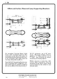
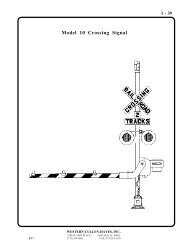
SECTION 2INSTALLATION INSTRUCTIONS - MODEL 10 SIGNAL1. Install foundation in proper location per the requirements of the installation.Refer to figures 1 and 2 for typical foundation details.Suggested Concrete Foundationfor <strong>Model</strong> 10 <strong>Gate</strong> Signal Using2149 Junction Box BaseGalvanized Steel FoundationNo. 1181-9Figure 1 Figure 211-11/16" Sq.Track Side17" Sq.Wire Entrance - 3-3/4" sq.Field Side10/05 8RoadsidePlan View of Type 2149Junction Box BaseFigure 2A
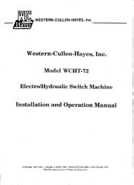
2. Remove the junction box cover to access the conduit adapter and hardware kit.Attach the conduit adapter to the top of the base. Loosen the base clamp bolts and installthe lower pipe shield in the bottom of the base. Insert the signal mast into the base andtighten the base clamp bolts. Place the base and mast assembly on the foundation with thejunction box cover facing oncoming traffic as shown in figure 3. Secure the assembly to thefoundation anchoring bolts.Typical <strong>Model</strong> 10 SignalFigure 35410/05 9
3. Secure the mechanism support assembly to the mast 48 inches above the top of the foundationin a position as shown in figure 4. Note: Adjustment may be required to position thegate arm at 3-6" to 4-6" above the roadway crown after the mechanism and gate arm areinstalled.4. Install 4 square head bolts into the slots in the rear of the mechanism case.Set the mechanism onto the support assembly. Install saddle clamps and nuts.Mechanism SupportMechanismCenter Line ofRoadway Arm25 Deg.Clamp TypeSupportClamp Type Mechanism Support InstallationFigure 410/05 10
5. Remove hole plugs from mechanism case. Install conduit fittings, adapters, cable gripand ventilator. Install the 1-1/2" sealtite from the base to the mechanism. Be sureenough slack is available to allow rotation of the mechanism.6. Remove nuts, washers and spline protectors from the ends of the mechanism main shaft.7. Make sure the main shaft is in the position it assumes when the gate arm is down(horizontal). This condition exists when segment gear (A) is resting on the horizontalstop pin (B) at point (C) as shown in figure 5.Ref. No.DescriptionABCDEFGHJKSegment GearHorizontal Stop PinClearence Gap 3/32" MinimumHorizontal Stop Spring HousingVertical Stop PinVertical Stop Pin NutClearance Gap 3/32" MinimumHorizontal Stop Pin LocknutHorizontal Stop Pin CoverVerical Stop Pin Cover3/32"Horizontal3/32"VerticalStop DetailFigure 510/05 11
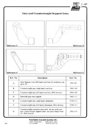
8. Refer to figure 6. Apply gate and counterweight support arms (B) to the mechanism mainshaft (A). Keeping the gate end of the supports in the down (horizontal) position, installwashers and hand tighten nuts on the main shaft.CAUTION: Do not apply counterweight before the roadway gate arm isinstalled.9. Install conversion bracket, breakaway adapter channel, or <strong>Gate</strong> Gard (D) to the counterweightsupport arms (B). Secure with provided hardware. The square head bolts fit intothe recess on the support arm with the threads facing outward.10. Tighten all installed hardware.11. Installation of fiberglass or aluminum/fiberglass gate arms.Assemble the arm by sliding sections together to achieve desired length. In some cases, itmay be necessary to drill holes in the inserted arm section. Secure sections with providedhardware.<strong>Gate</strong> and CounterweightSupport InstallationFigure 6Ref. No.AMain ShaftDescriptionBDEF<strong>Gate</strong> and Counterweight Support ArmsConversion Bracket or AdapterCast Breakaway Adapter<strong>Gate</strong> Arm Section10/0512
PIVOT TYPE BREAKAWAY ADAPTERReferring to figure 6, page 12, insert the cast breakaway adapter (E) into the gate armend section (F) and secure with provided hardware. Position the gate arm with adapterattached 90 degrees from the mechanism assembly. Slip adapter onto mounting pin. Rotatearm 90 degrees, until the holes in the adapter align with the holes in the conversion bracket.1 2 3Figure 7Install brass shear bolts in holes as instructed below. <strong>Gate</strong> arm length is measured from thecenterline of the signal mast.0-18' <strong>Gate</strong> Arms - Holes 2 and 319'-28' <strong>Gate</strong> Arms - Holes 1 and 2Over 29' <strong>Gate</strong> Arms - Holes 1, 2 and 3GATE GARD ADAPTERReferring to figure 6, page 12. Install the <strong>Gate</strong> Gard (D) adapter onto the counterweight arms(B). Observe instruction sheet provided with the <strong>Gate</strong> Gard. Install gate arm (F).Figure 810/0513
12. Install gate arm lights using provided hardware. Attach cable to the arm using eyelets provided. Leaveslack in th cable between eyelets to provide drip points. Route cable through cable grip installed in themechanism and terminate wires at required binding posts or fuse block panel. Refer to figure 9 for properlamp spacing.13. Install signal light units, signs and bell or pinnacle as required. Complete electrical wiringto these units.Specifiedlength ofgate armDimension"A"Dimension"B"Dimension"C"14 Ft. 6" 36" 5'-0"15 Ft. 18" 36" 5'-0"16-17 Ft. 24" 36" 5'-0"18-19 Ft. 28" 41" 5'-0"20-23 Ft. 28" 4-0" 5-0"24-28 Ft. 28" 5-0" 5'-1"29-31 Ft. 36" 6-0" 6'-0"32 Ft. 36" 7-0" 7'-6"Suggested Roadway <strong>Gate</strong> Arm Light SpacingFigure 9NOTE: THE INSTALLATION MUST BE PROPERLY WIRED AND POWER APPLIED ATTHIS TIME, AND FROM THIS TIME FORWARD.14. Installation of CounterweightsOblong counterweights on cast iron or aluminum counterweight armsRefer to figure 10 and table 1, page 15.Install the counterweight support plate to the counterweight arm by inserting the clampwasher (short) studs through the slot from the outside of the arm. Install the clamp washers,flat washers and nuts to the studs. Locate the support plate at the furthermost end ofthe slot in the counterweight arm. Tighten the clamp washer nuts. Be sure that the teethin the clamp washers are seated into the teeth on the inside of the counterweight arm.Raise and secure the gate arm in the up (vertical) position. Install the counterweights tothe counterweight (long) studs. Install the flat washers and nuts to these studs and handtighten the nuts. If two counterweight arms are supplied, distribute the weights evenly onthe two arms. Align the weights and insert the alignment bolt into the holes at the bottomof the weights.10/05 14
Install washers and nut onto the alignment bolt and securely tighten. Now position the weightsat the furthermost travel, way from the roadway, in the slots in the weights. Securely tighten thecounterweight nuts. Lower the gate arm to the horizontal position.Support PlateClamp WasherCounterweightsCounterweightNut and WasherClamp Washer StudClamp Washer Nut and WasherCounterweight StudCounterweight ArmFinal Counterweight PositionFigure 10Table 1Table of weight forfiberglass and aluminum/fiberglass gate arms<strong>Gate</strong> ArmLength in FeetCounterweightin PoundsCounterweightat 47lb.18 386 819 Thru 24 433 925 Thru 28 470 1029 Thru 32 517 11There are no vertical or horizontal torque values for the <strong>3597</strong>-FC-301 <strong>Gate</strong> Mechanism.10/05 15
10/05 16SECTION 3INTERNAL ADJUSTMENTS1. Power Down Operation, Horizontal Position Adjustment.When the crossing system gate relay de-energizes, drops, the motor brake is released.Then through the #1 front power down contact, relays 1MCR energize and apply powerto the motor through the down resistor (PDR). When the gate reaches the horizontalposition, the #1 contact transfers to the back, removes motor power and then appliespower to the brake to hold the gate horizontal. This action is enhanced via a high risesliding cam assembly.The horizontal position is controlled by the position of the #1 contact cam.The gate horizontal position would place the gate parallel to the crown of the roadwayand between 3'- 6" to 4' 6" above the crown of the roadway.If horizontal adjustment is required, adjust the #1 contact cam. Place the gate in thehorizontal position. From the brake terminal block, located at the rear of the motor, installa jumper wire from terminal BR+ to terminal 6A on the circuit board, and a jumper fromterminal BR- to terminal 7A on the circuit board. This will apply the brake. Adjust thecam while being sure that the sliding portion of the cam is fully upward in the cam frame.Remove jumper wire, cycle gate and re-check position. Repeat this procedure as necessaryto achieve proper horizontal gate position.When complete, check the mechanism horizontal stop pin clearance. Check this with 3/32"wire gauge, PN: 3590-1013. The minimum gap between the segment gear and thehorizontal stop pin is 3/32". The maximum gap is 1/8".DO NOT PLACE HANDS INTO THE GEAR AREA WHEN CHECKING THISCLEARANCE.If horizontal stop pin adjustment is required, refer to figure 5, page11. Remove the stoppin cover (J). Loosen the stop pin locknut (H). Turn the stop pin assembly (D) as requiredto obtain the specified clearance between the segment gear (A) and stop pin (B) at point(C). Tighten the lock nut and replace the cover.2. Power Descending Time.Check the gate power down time. The gate should descend between 10 and 15 secondsfrom the time the gate down command is given to the time the gate is horizontal. Thisspeed is adjusted with the Down Resistor, (PDR) located on the back wall of the mechanismcase. To increase the speed, move the resistor slide up, to decease the speed, movethe resistor slide down. Be sure the slide shoe rests on top of the resistor wire.NOTE: Never set a gate to descend at more then 15 seconds.3. <strong>Gate</strong> Up Operation, Vertical <strong>Gate</strong> Position. Contact Cam Adjustments andVertical Stop Adjustment.When the crossing system gate control relay de-energizes, drops, the motor brake isreleased. The counterweights begin to fall thus raising the gate. The electronic gatemonitor (EGM) will trip and apply the shorting resistor circuit. The gate speed willthen be reduced as per the adjustment of the shorting resistor (SHR).
Once the gate reaches 45 degrees, the #6 contact closes which resets the EGM and appliesup power to the motor. At 75 degrees, the #7 contact will open and remove up power fromthe motor.The #2 back contact controls the final vertical position of the gate. After the #7 contactopens and removes motor power, the gate will coast until the #2 back contact closes andapplies power to the brake.If vertical adjustment is required, adjust the #2 contact cam. Place the gate in thevertical position. From the brake terminal block, located at the rear of the motor, installa jumper wire from terminal BR+ to terminal 6A on the circuit board, and a jumper fromterminal BR- to terminal 7A on the circuit board. This will apply the brake. Adjust thecam while being sure that the sliding portion of the cam is fully downward in the camframe. Remove jumper wire, cycle gate and re-check position. Repeat this procedure asnecessary to achieve proper vertical gate position.If the #2 cam was adjusted, check the position of the gate clear contact cam #4.Adjust the cam so that the cam follower is resting completely on the end of the camsurface, not on the cam ramp, when the gate is in the vertical position.When complete, check the mechanism vertical stop pin clearance. Check this with a 3/32"wire gauge, PN:3590-1013. This is the minimum clearance between the segment gear andthe vertical stop pin. There is no maximum specification.DO NOT PLACE HANDS INTO THE GEAR AREA WHEN CHECKING THISCLEARANCE.If vertical stop pin adjustment is required, refer to figure 5, page 11. Remove th stop pincover (K). Turn the stop pin nut (F) as required to obtain the minimum 3/32" clearancebetween the segment gear (A) and the stop pin (E) at point (G). When complete, replacethe stop pin cover.4. <strong>Gate</strong> Up Time.To adjust the speed of the gate as it rises, it will be necessary to adjust the shortingresistor (SHR). This resistor is located on the mechanism relay panel.To increase the gate speed, move the resistor slide to the right. To reduce the speed, movethe resistor slide left.5. Contact Cam General Information.Refer to figures 11A and 11B, page 20.Cams and contacts are factory set at the positions shown on the wiring diagram, plus or minus2 degrees. This setting is considered a starting point as some cams will be adjusted during installation.Be sure that the slots in the sliding cams are kept free of foreign material at all times and that cam andcam follower surfaces are clean.There are three different cams in the <strong>3597</strong>-FC-301 mechanism. Cam #1 is a sliding high-rise camPN: 38-0045-531, cam #2 and #7 are standard sliding cam PN: 38-0045-92, and the remaining camsare standard fixed cams PN: 38-0045-55.10/05 17
When replacing a cam, be certain that the proper cam is used in the proper position.When adjusting or replacing any cam, care should be taken when tightening the capscrew. Referring tofigure 11B. The motor up cam has a slotted insert (G), which allows for radial travel. When cam insert(H) is rotated to the closest point toward cap screw (L), a mini mum gap of 1/16" must be maintainedbetween the cap screw and the cam insert at location (J).Referring to figure 11A, for all fixed cams a minimum gap of 1/16 inch must be maintainedbetween cam insert (E) and cap screw (A) at position (K).Contact #3, 4 and 5 are for customer use and there are no other specific instructions.Contact #4 is for customer use to indicate a gate clear condition. Specific instructions for thiscam are given in paragraph 3 of this section. Specific instructions for cams #1,2,6 and 7 are discussedin paragraphs 1 and 3 of this section.6. Circuit Controller Contact AdjustmentContact Tension is listed on the wiring diagram and should be periodically checked.To adjust a contact, it will be necessary to bend the contact spring to achieve the following specificationsby using the contact adjusting tool, PN: ES-6104-2, an ounce spring scale,PN: 3565-211 and a 1/16 inchinsulated gauge PN: 3590-1010.When adjusting contacts, gently bend the contact spring by applying several gentle upward or downwardforces against the contact spring. Recheck the gap or pressure after each operation. Repeat this procedure until specification is achieved. Overbending may damage the contact and make it impossible toachieve proper contact spring pressure. Always apply the adjusting tool at the top of the contact directlybeneath the circuit controller board. Never bend the contact body or at the bend near the contactingsurface. Do not twist the contact while bending. Minimum contacting area must be 1/4 inch.a. To adjust contacts 3 thru 7 follow these procedures. Inspect and adjust any contactthat appears to have 1/8 inch or greater gap. Refer to figure 11A.1. With the contact in the fully open position, the clearance between the camfollower (B) and the metal frame of the cam (C) must be a minimum of 1/16inch. To adjust, bend the back or heel contact until specification is achieved.2. With the contact in the fully open position, the clearance between the contactingsurfaces (D and F) must be a minimum of 1/16 inch. To adjust, bend thefront contact until specification is achieved.Using an ounce spring scale, PN: 3565-211, and contact adjusting tool, PN: ES-6104-2, adjust contactspring pressure as follows. Refer to figure 11A and specification items (D) and (F).10/05 18
Position the gate so that the contact cam follower (B), is well upon the cam surface (E) or (H) and the contactis fully closed. Hook the end of the scale to the front contact at the bend (F), near the contacting surface andlift gently until the contact opens. To adjust, bend the front contact while the contact is closed. To reducepressure, bend the contact away from the cam. To increase pressure, bend the contact toward the cam.b. There is a front and back contact at position #1, and a back contact at position #2.Refer to figure 11A. The gap specification for the #1 contact is a minimum of 1/8inch. Inspect and adjust if the gap appears to be greater then 3/16 inch. The gapspecification for the #2 contact is minimum of 1/16 inch. Inspect and adjust if thegap appears to be geater than 1/8 inch.To adjust the front contact, follow the proceeding procedure. To adjust the back contacts, follow these procedures:1. To check and adjust the #1 back contact, place the gate vertical.Check the gap (D) using a 1/8 inch or 2, 1/16 inch insulated gauges.2. Lower the gate. Install a jumper wire from circuit controller terminal 2A toterminal 6A. This will apply the brake.Attach the scale to the heel contact at a position just below the cam follower(B) and lift gently until the contact just opens. Note the scale reading.3. To check the #2 back contact, place the gate horizontal. Check the gap (D)using a 1/16 inch insulated gauge.4. Raise the gate. From the brake terminal block, located at the rear of themotor, install a jumper wire from terminal BR+ to terminal 6A on the circuitboard, and a jumper from terminal BR- to terminal 7A on the circuit board.This will apply the brake. Attach the scale to the heel contact at a positionjust below the cam follower (B) and lift gently until the contact just opens.Note the scale reading.DO NOT CHECK THESE CONTACT WITHOUT THE JUMPER WIREINSTALLED, AS WHEN THE CONTACT OPENS THE BRAKE RELEASESAND THE GATE AND GEARS WILL MOVE. BE CAREFUL NOT TOSHORT THE CONTACTS WITH THE SCALE. INSTALL JUMPER WIREDESCRIBED ABOVE TO PREVENT MOVEMENT.5. To adjust the gap or tension, adjust the back contact (M) using PN:ES-6104-1 contact bending tool for contacts with stiffeners. Always bendthe contact while it is closed. To reduce pressure, bend the contact towardthe cam. To increase pressure, bend the contact away from the cam.CAUTION: Do not overbend the contacts. Overbending may damage a contactand make it impossible to achieve the correct gap or contact springpressure.10/05 19
MDCam and Contact DetailFigure 11 ASliding Cam DetailFigure 11 BContact Tension: #1, 2 and 7 = 18 to 28 oz.All others = 16 to 24 oz.Ref. No.DescriptionRef. No.DescriptionACap ScrewGCam SlotBCDCam FollowerCam Frame1F and 1B minimum gap 1/8"All others minimum gap 1/16"H Cam Insert SurfaceJ Minimum Gap 1/16"K Minimum Gap 1/16"ECam Insert SurfaceLCap ScrewFAttached Spring ScaleMBack Contact10/05 20
SECTION 4GENERAL MAINTENANCEPlease contact <strong>Western</strong>-<strong>Cullen</strong>-<strong>Hayes</strong> at 773-254-9600 if you have anyquestions or need assistance with any aspect of the <strong>3597</strong>-FC-301 <strong>Gate</strong>Mechanism.1. Service and Tests.All mechanisms are given a final inspection and are properly lubricated and adjustedbefore shipment from the factory. Following is a list of setup and general checks.a. Supply voltage should be maintained between 12 and 16 volts DC.Check supply voltage at the 6A and 7A circuit controller terminals.b. Operate the mechanism through an up-down cycle and note operating voltage. Asthe gate goes down, voltage should not drop below 11 volts and current should rangefrom 15 to 30 amps. Readings will vary depending on the length of gate arm. Ifvoltage drops below 9 volts, check power supply between the battery and the mechanismterminal points for proper wire sizing and voltage drop. Refer to wiring specificationsin section 1.c. Perform a gate up test. Lower the gate. Place the cam switch in the test position.The gate will begin to rise, then the EGM will trip thus slowing the gate. When thegate is near vertical, it will swing free as the brake is not applied when the camswitch is in the test position. When complete, press the EGM reset button andplace the cam switch in the run position. The gate will power down.d. Raise the gate. Check the gate power down time. The gate should descend between10 and 15 seconds from the time the gate down command is given to the time thegate is horizontal. This speed is adjusted with the Down Resistor, (PDR) locatedon the back wall of the mechanism case. To increase the speed, move the resistorslide up, to decease the speed, move the resistor slide down.NOTE: Never set a gate to descend at more than 15 seconds.e. Check the clearing time. The gate should clear between 7 to 11 seconds. To adjustthe speed of the gate as it rises, it will be necessary to adjust the shorting resistor(SHR). This resistor is located on the mechanism relay panel. To increase the gatespeed, move the resistor slide to the right. To reduce the speed, move the resistorslide left.f. Check for grounds in the battery and control circuit wiring.g. Check relays as required by your railroad procedures and intervals.The (MCR) relay specifications are: Voltage: 12vdcCoil Resistance: 33 +/- 10% , Power: 4.4WNominal pull in voltage: 9.6Nominal drop out voltage: 1.2 or moreReplace any relay that fails to pick by 10 vdc.10/05 21
The (GCR) relay specifications are: Voltage: 12 vdcCoil Resistance: 188 ohm +/- 15%Nominal pull in voltage: 9.6Nominal drop out voltage: 1.2 or moreReplace any relay that fails to pick by 10 vdc.h. Perform a gate obstruction test. Place a DC voltmeter onto the power supplyterminals. B on terminal 6A and N on terminal 7A. Place the gate in thevertical position with the crossing controls. Place a bolt or pin into a hole in thelower cluster gear. Place the test switch in the test position. The gate will releasewhich will allow the cluster gear to rotate and the blocking bolt to rest upon themechanism case. Then press the EGM reset button and place the cam switch in therun position. Check to be sure that voltage does not drop below 9 volts. After atime delay of not more than 30 seconds, the EGM should trip and release powerfrom the motor. The gate should then hang free. If voltage drops below specificationand the EGM does not release motor power, refer to the wiring requirementslocated in section 1.NOTE: The mechanism can be used even if excessive voltage drop causesa failure of this test. However, the obstruction and/or thehorizontal gate arm anti-pumping will be inoperative which maycause damage to control components.i. If a total failure of the EGM unit occurs, the gate will not be operational.Do not attempt to operate a <strong>3597</strong>- FC-301 mechanism if the EGM unit hasfailed. Remove the gate from service and replace the EGM as soon aspossible.To remove a single <strong>3597</strong>-FC-301 from service, hold the gate in the vertical position.From the brake terminal block, located at the rear of the motor, install a jumperwire from terminal BR+ to terminal 6A on the circuit board, and a jumper fromterminal BR- to terminal 7A on the circuit board. This will apply the brake. Thenplace the cam switch in the test position. While wired and set in this manner the<strong>3597</strong>-FC-301 will not operate.j. The potentiometer of the EGM is factory set to trip at a minimum of 19 VDC.Field adjustment should not be required. To field test the EGM trip voltage:1. Attached a recording DC voltmeter to the MA (orange) and MB (yellow)terminals on the EGM.2. Lower the gate with the crossing controls. Place the cam switch in thetest position. Observe the peak voltage on the meter, as the gate raises.3. If the reading is above 20 volts, the test is complete. Press the EGM resetbutton and place the cam switch in the run position to lower the gate.4. If the voltage is less than 20 volts, adjust the potentiometer clockwise oneturn. Repeat this test and adjustment until a reading of 20 to 21 volts isachieved.5. Press the EGM reset button and place the cam switch in the run position toraise the gate.10/05 22
k. The motor brake does not require any service. Brake coil resistance is 11 ohms.Current draw at 12vdc is 1.09 amps, or 13 watts.l. To lower the gate counterweight assembly (raise weights) control the gate downwith the crossing system controls. The motor brake will hold the mechanism inthe horizontal position for gate arm service.m .The red LED is lit when nominal 12 vdc power is present. The green LED is litwhen the EGM is normal and the EGM relays are energized. If the green LED isnot lit, try to reset the EGM by pressing the reset button. Both LED's must be litfor proper gate operation.2. Lubrication.Time interval for periodic lubrication will be governed by usage.The mechanism gear train, main shaft and motor bearings are pre-lubricated and sealed.No periodic lubrication is required for these bearings.The gear teeth are to be lubricated periodically with, PN: 3590-1650, Bison all-temperaturelubricating grease.3. Motor Service.Refer to figure 13, page 28.The motor has a totally enclosed, non-ventilated housing and has prelubricated sealedbearings.The motor brushes should be periodically inspected for wear. Replace brush (11 and 12)when carbon portion has worn to 5/8 inch length or less.NOTE: Motor brush caps (13) screw on. Remove caps by turning counterclockwise.Hand tighten only when replacing caps. Always remove motorbrushes (11) when gate arm is in the vertical position. No dynamic brakingis provided with a brush removed. Always replace brushes EXACTLYin the position they were in.10/05 23SECTION 5OPTIONAL EQUIPMENT1. Heater may be attached to the mechanism for prevention of frost formation oncontroller contacts, (figure 17, page 32).2. <strong>Gate</strong> lamp fuse kit PN:38-0045-540 (figure 16, page 31).3. Setup and adjustment tools are listed on the last page of the mechanismparts section.
SETUP CHECKLISTLocation: _______________________________In Service Date: ______________1. Supply voltage between 12 and 16 vdc. _____2. Voltage during gate down cycle. _____ volts3. Amperage during gate down cycle. _____ amps4. <strong>Gate</strong> up / EGM test. _____5. Check and adjust descending time. Resistor thumb screws tight. _____ seconds6. Check and adjust gate clearing time. Resistor thumb screw tight. _____ seconds7. Check for grounds in wiring. _____8. Obstruction test. Pass______Fail_____9. <strong>Gate</strong> parallel to roadway surface. _____10. Counterweights installed all the way back and all the way up,as viewed with the gate in the horizontal position. _____11. 3/32 inch clearance between segment gear and horizontaland vertical stops. _____12. Contact cams adjusted per instructions. _____Installed By: ______________________Checked By: ______________________10/05 24
10/05 25SECTION 6<strong>3597</strong>-FC-301 CROSSING GATE MECHANISMREPLACEMENT PARTSFigure 12
<strong>3597</strong>-FC-301 CROSSING GATE MECHANISMREPLACEMENT PARTSRefer to Figure 12Ref.No.D escriptionPart No.1 BearingCover38-0045-302 Spring,Vertical Stop38-0045-383 SpacerTube38-0045-424 Cam Assembly38-0045-55A MotorAssembly<strong>3597</strong>-20-226 SlidingCam Assembly38-0045-92D RelayPanel Assmbly<strong>3597</strong>-388 WiringDiagram<strong>3597</strong>-FC-301-WD9 ClusterGear Shaft38-0045-26710PlasticPlug38-0045-27411HorizontalStop Pin Assembly38-0045-305122"Conduit Locknut38-0045-31413Ventplug1265-6-B14HaspAssembly1265-40-115MainShaft Bearing3580-16616EndCap3580-29117Gasket3580-28118SegmentGear3590-219-F19ClusterGear3590-220-F20MainShaft Bearing3590-22221NylockNut for Vertical Stop Assembly3590-23122MainShaft Cap3590-23223Mechanism Case3590-234-7-M24Mechanism Cover Sub-Assembly3590-240-2-M25Bearing3590-24926SetScrew3590-25127WoodruffKey3590-25428Spacer3590-27729Spacer3590-27830Spacer3590-27931VerticalStop Pin Assembly3590-29332Mountingand Hardware Kit3590-29410/05 26
<strong>3597</strong>-FC-301 CROSSING GATE MECHANISMREPLACEMENT PARTS (CONTINUED)Refer to Figure 12Ref. No. Description Part No.33 Bison Grease 3590-165034 Pipe Plug 6560-5135 8-32 x 3/8" Button Head Socket Head Cap Screw BB-32-BB-3-003736 1/4-20 x 3/4" Hex Head Socket Cap Screw BB-23-EE-3-007537 1/4-20 x 1/4" Hex Head Socket Cap Screw BB-23-EE-3-012538 3/8-16 x 3/4" Low Head Socket Cap Screw BB-59-JJ-3-007539 1-1/4" Hex Nut JJ-12-AD-340 1-1/4" Plain Washer 3570-11441 Staple 1265-442 1/4-20 x 3/8" Hex Head Socket Cap Screw BB-23-EE-3-003743 Stop Assembly Cover 38-0045-329-M44 Eyebolt 3590-38145 Bearing Cap Spacer 3590-27546 Four Hole Cluster Gear 3590-220-H47 3/8-16 HD Square Nut HH-11-JJ-348 3/8 Split Lockwasher RR-00-AM-349 3/8-16 Nylock Hex Nut AL-12-JJ-350 1/3 ohm Resistor (PDR) 1110-3351 Hi-Rise Sliding Cam Assembly 35-0045-53152 #10-24 x 1-1/4" Round Head Machine Screw AA-10-CC-3-012553 #10 Split Lack Washer RR-00-AH-354 Pinion Gear <strong>3597</strong>-2255 5/16"-18 x 2-1/4 Hex Head Bolt CC-12-GG-3-022556 38"-16 Hex Nut HH-12-HH-357 1/4" Plain Washer PP-00-AJ-358 5/16"-18 Hex Nylock Nut AL-12-GG-3C Circuit Controller Assembly 38-0045-502E <strong>Gate</strong> Lamp Fuse Panel 38-0045-540F Contact Heater10/05 27
<strong>3597</strong>-20-22 MOTOR ASSEMBLYREPLACEMENT PARTSReference AFigure 13Ref. No Description Part No.Motor Assembly Complete <strong>3597</strong>-20-221 Motor <strong>3597</strong>-20-22 Terminal Block 2506-23 1/4-20 x 3/4" Nylock Hex Head Screw <strong>3597</strong>-234 Motor Brake <strong>3597</strong>-165 Motor Pinion <strong>3597</strong>-226 1/8" x 1/4" Woodruff Key <strong>3597</strong>-217 Washer 38-0045-2418 8-32 x 1/2" Nylock Round Head Machine Screw BJ-10-BB-3-0059 AAR Washer 1070810 Crimp Terminal 31908-MT11 Clamp Nut 1070712 Binding Nut 1070613 Motor Brush <strong>3597</strong>-20-1314 Brush Cap <strong>3597</strong>-20-1215 Brush Holder <strong>3597</strong>-20-1416 Coupler Bolt <strong>3597</strong>-2410/05 28
38-0045-502 CIRCUIT CONTROLLER ASSEMBLYREPLACEMENT PARTSReference CFigure 1410/05 29Ref. No. Description Part No.1 Terminal Board 38-0045-502-12 Back Contacts 3 thru 7 38-0045-273 Front Contact 3 thru 7 38-0045-284 Insulator Sleeve 38-0045-29-A5 Insulator Washer 38-0045-29-B6 Binding Post Seat 38-0045-777 Insulator Sleeve 38-0045-5258 Binding Nut 107069 Clamp Nut 1070710 AAR Washer 1070811 1-7/8" Binding Post 10709-212 2-1/4" Binding Post 10709-313 Back Contacts 1 & 2 38-0045-52014 Heel Contact. Contact 1 38-0045-52115 Contact Stiffener 38-0045-52216 Front Contact. Contact 1 38-0045-52317 Insulating Block 38-0045-50518 Riser Block 38-0045-52619 6-32 x 1-1/4" Philllister Head Machine Screw 38-0045-52720 Heel Contact. Contact 2 38-0045-52421 Connecting Plate 1705-4
<strong>3597</strong>-38 RELAY PANEL ASSEMBLYREPLACEMENT PARTSReference DFigure 13Ref.NoD escriptionPart No.1 RelayPanel<strong>3597</strong>-3-12 Cam Switch Panel<strong>3597</strong>-3-223 Relaywith Cover91254-124 Electronics<strong>Gate</strong> Monitor<strong>3597</strong>-15 Cam Switch<strong>3597</strong>-26 Cam Switch Knob<strong>3597</strong>-2-17 CableClamp1953-6-A8 CableClamp1953-12-B9 Cam Lube Label38-0045-500102.2Ohm Resistor1110-31112vdc Relay50-3012-1212RelaySocket50-301310/05 30
38-0045-540GATE LAMP FUSE PANELREPLACEMENT PARTSReference EFigure 16Ref. No Description Part No.1 Terminal Block 2508-69-42 Panel 38-0045-5413 10 AMP Type ATC Fuse 400-35-504 Fuse Holder 50-02745 Crimp Terminal 31908-MT10/05 31
<strong>3597</strong>-FC-301 CROSSING GATE MECHANISMCONTACT HEATER ASSEMBLYReference FFigure 17Ref. No. Description Part No.F Contact Heater Assembly Complete, 115 VAC, 50 Watt, 500 Ohms <strong>3597</strong>-4F1 Contact Heater Assembly Complete, 24 VDC, 50 Watt, 25 Ohms <strong>3597</strong>-5F2 Contact Heater Assemmbly, 12 VDC, 50 Watt. 10 Ohms <strong>3597</strong>-610/05 32
Set-Up and Adjustment ToolsSpring Scale, PN: 3562-210Used for measuring gate arm torque.Torque wrench with socket, PN: 3590-K-9.Used for measuring gate arm torque.Snap ring pliers, PN: 3590-1007Used for ratchet wheel removal..020 gauge, PN: 3590-1012Used to adjust ratchet wheel to hold clear pawl clearance..032 gauge, PN: 3590-1011Used to adjust gap on hold clear mounted power down contact.Ounce spring scale, PN: 3565-211Used to measure contact spring pressure.1/16" insulated gauge, PN: 3590-10101/8" insulated gauge, PN: 3590-1015Used to check contact gap.Contact bending tool for contacts without stiffeners, PN: ES-6104-2Contact bending tool for contacts with stiffeners, PN: ES-6104-1Used to adjust circuit board contact.Angle finder, PN: 3590-1014Used to set contact cam operating position.3/32" wire gauge, PN: 3590-1013Used to check vertical stop to segment gear clearance.Tool kit, PN: 3590-K-11<strong>Inc</strong>ludes snap ring pliers, 3/32", 3/16" and 7/32" To handle allen wrenches, 7/16"combination wrench and canvas pouch.Bison all temperature lubricating grease, PN: 3590-1650For lubrication of gears and contact cams, 1 quart can.10/05 33