WCH Sliding Derail Booklet - Western-Cullen-Hayes Inc.
WCH Sliding Derail Booklet - Western-Cullen-Hayes Inc.
WCH Sliding Derail Booklet - Western-Cullen-Hayes Inc.

Create successful ePaper yourself
Turn your PDF publications into a flip-book with our unique Google optimized e-Paper software.
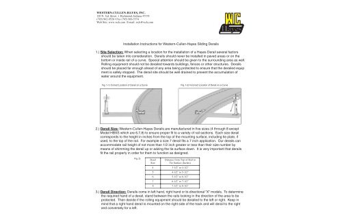
WESTERN-CULLEN-HAYES, INC.120 N. 3rd. Street • Richmond, Indiana 47374(765) 962-0526 • Fax (765) 966-5374Web Site: www.wch.com E-mail: wch@wch.comInstallation Instructions for <strong>Western</strong>-<strong>Cullen</strong>-<strong>Hayes</strong> <strong>Sliding</strong> <strong>Derail</strong>s1.) Site Selection: When selecting a location for the installation of a <strong>Hayes</strong> <strong>Derail</strong> several factorsshould be taken into consideration. <strong>Derail</strong>s should never be installed in paved areas or on thebottom or inside rail of a curve. Special attention should be given to the surrounding area as well.Rolling equipment should not be derailed towards buildings, fences or other structures. <strong>Derail</strong>sshould be placed far enough ahead of any area being protected to ensure that the derailed equipment is safely stopped. The derail site should be well drained to prevent the accumulation ofwater around the equipment.Fig. 1-1) Correct Location of <strong>Derail</strong> on a Curve Fig. 1-2) <strong>Inc</strong>orrect Location of <strong>Derail</strong> on a Curve2.) <strong>Derail</strong> Size: <strong>Western</strong>-<strong>Cullen</strong>-<strong>Hayes</strong> <strong>Derail</strong>s are manufactured in five sizes (4 through 8 exceptModel HBXS which are 6,7,8) to ensure proper fit to a variety of rail sections. Each size derailcorresponds to the height in inches from the top of the mounting surface, including tie plate, ifused, to the top of the rail. For example a size 7 derail fits a 7 inch application. Our derails canaccommodate rail height of not more than 1/2 inch greater or less than their size number bymeans of shimming the derail up or adzing the tie surface down. It is very important that derailsfit the rail properly in order for them to function as designed.Fig. 2)Deail Distance from Top of RailSizeTie Surface (<strong>Inc</strong>hes)4 3-1/2" to 4-1/2"5 4-1/2" to 5-1/2"6 5-1/2" to 6-1/2"7 6-1/2" to 7-1/2"8 7-1/2" to 8-1/2"to3.) <strong>Derail</strong> Direction: <strong>Derail</strong>s come in left hand, right hand or bi-directional “X” models. To determinethe required hand of a derail, stand between the rails looking in the direction of the area to beprotected. Then decide if the rolling equipment should be derailed to the left or right. Keep inmind that a right hand derail is mounted on the right side of the track and will derail to the rightand conversely for a left.
Fig. 3-1) Side Selection - <strong>Derail</strong>ing Intruding Equipment.Fig. 3-2) HB Right Hand <strong>Derail</strong> with Crowder and Hi-Rise Operating Stand Fig. 3-3) <strong>Derail</strong>ling Intruding Equipment to the left.<strong>Derail</strong> intruding equipment by placing the derailon outside curve of track, where the path of derailedwheels will be clear of obstructions & other equipment.If located on a curve he <strong>Derail</strong> must be also positioned on the outsideportiion of the curve as shown (unless used in conjunction with a WheelCrowder). Left Hand HB <strong>Derail</strong> with optional Hi-Rise Operating Standare shown here.This is important when placing the Operating Stand as well. Ample clearance must be providedbetween adjacent tracks and other possible equipment or structures. Care should be taken to avoidderailing toward buildings, ditches, paved areas or other tracks where derailed equipment couldobstruct movement on that track. Bi-directional “X” derails should only be used when it is absolutelynecessary to derail equipment entering and exiting a specific area, such as a locomotive shop.4.) Installation: Once the location, size and direction of the derail have been determined the finalinstallation takes just a few minutes. The two crossties under the derail should be new, grade5 ties at least 14 feet long. The ties should be parallel and level and well ballasted.
Fig. 4-1) Plan View of Installed <strong>Derail</strong>.Fig. 4-2) Rear View of <strong>Derail</strong> showing connecting lugs and dimensions.If tie plates are used, they must be cropped even with the base of the rail on the gauge side of therail. Particular attention must be paid to the height of the rail and tie plates, either shim the derail oradz the ties as required. Remember, the total height of the derail must equal the total height of therail and tie plate combination. For example, a rail and tie plate 7-1/2 inches high should have anumber 7 derail with a 1/2 inch shim under it so they equal 7-1/2 inches as well.Fig. 5) Measure from the top of ties to the top of rail, cropping tie plates first (as shown).Place the derail between the rails and shove the front of the guide box to within 1/2 inch of the webof the rail. Remove the two wire ties that secure the derail block to the box for shipping purposes.Next, slide the derail block up and onto the railhead as far as it will go. It should overhang the railhead by a minimum 1/2 inch to the field side. Now, push the derail box toward the web of the rail untiljust before the derail block starts to lift up. At this point, the thrust shafts and seats have made contact.When properly installed there should be no gap between the top of the rail and the underside ofthe derail block and no gap between the thrust shafts and the seats in the derail guide box. Makesure the vertical flanges of the guide box are flush against the crossties. The derail block should belevel on the top of the rail and the vertical stops under the derail block will be against the gauge of therail head. Next lag bolt the derail to the crossties using all the available holes in the horizontalflanges. These holes are 31/32 inch in diameter and will accommodate bolts up to 15/16 inch. Whenin the derailing position, the derail block should cover the head of the rail completely and over hangthe rail 1/2 inch minimum, to the field side.
Fig. 6) Fig. 7) Fig. 8)Size 6 <strong>Derail</strong> on a 6” application. Size 6 <strong>Derail</strong> on a 6-1/2” application. Size 6 <strong>Derail</strong> on a 5-1/2” application.5.) Operating Stands: <strong>Western</strong>-<strong>Cullen</strong>-<strong>Hayes</strong> manufactures four types of manual operating standsfor our sliding derails, a high rise stand, standard two tie stand, a one tie stand and low profile twotie stand. The standard connecting rod for the high-rise stand is 8’-2” long. The one and two tiestand rod is 5’-2”, the rod for the close coupled stand is 3’-1”, other rod lengths are available. Ifusing a manual switch stand or power switch machine to operate a <strong>Hayes</strong> <strong>Sliding</strong> <strong>Derail</strong>, a ShortStroke <strong>Derail</strong> must be specified.Fig. 9) HB R.H. <strong>Derail</strong> withTwo Tie Operating Stand,Near rail application.Fig. 10) HB R.H. <strong>Derail</strong> withHi-Rise Operating Stand,Far rail application,Fig. 11 ) HB R.H. <strong>Derail</strong> withHi-Rise Operating Stand,Near rail application.6.) Place the operating stand on the field side of the track closest to the derail. With the derail in the“on rail” position and the operating stand in the “on rail” position the eye bolt angled away fromthe derail. Attach the connecting rod screw jaw to the center lug of the derail and to the eye boltof the operating stand. The connecting rod should be parallel to the ties. The connecting rodshave screw jaws on both ends to permit minor adjustment of the rod length. The stroke of theoperating stand is adjusted by means of the eyebolt to which the connecting rod is attached. Theworking stroke of a standard derail is 6-1/4 inches. There is a special 5-1/4 inch short strokederail identified by a “SS” on its nameplate. Make sure the connecting rod is parallel to the ties.Secure the operating stand to the cross ties using just two lag bolts.
7.) Now, check the operation of the derail and operating stand combination, simply rotate theoperating stand handle and observe the motion of the derail. If the derail and stand are installedcorrectly, the derail block will lift up and drop neatly back into the derail guide box, and thehandle will fall into the lockable position on the stand. If the derail does not sit completely downon top of the box side plates the eyebolt will need to be adjusted. If the operating stand handlelocks before the derail is down completely, unfasten the connecting rod and lengthen the eyeboltby turning it counterclockwise. If the derail sets down completely before the operating handlereaches the lockable position, shorten the eyebolt by turning it clockwise. Now, adjust the connectingrod and reinstall. Operate the derail to the “on rail” position, it should rise about 1 inchabove the head of the rail and then fall firmly on top of the rail with no clearance between theunderside of the derail block and the top of the rail. This allows the weight of the wheel to betransferred through the derail block directly to the rail, ties and ballast.After confirming the correct installation and operation of the derail install lag bolts in remaining holesprovided, make sure all rod connections are secure. The derail is now ready for service.
HB <strong>Derail</strong>(Installed)Nomenclature - HB <strong>Derail</strong>
HB <strong>Derail</strong> Dimension DiagramModel HB side view on-railDimension TableDERAIL SIZE A B C D5 5 " 1 -1/8"2 -9/16"6-3/8"6 6 " 31/32"3 -9/16"7-3/8"7 7 " 1 -1/8"4 -9/16"8-3/8"8 8 " 1 -1/8"5 -9/16"9-3/8"Model HB closed (off rail) showing ampleflangeway clearance.Std. HB Right Hand <strong>Derail</strong> Size 6 (HB6R) Shown.Left hand <strong>Derail</strong> is Opposite (HB6L not shown).Drawing is Not To Scale.Two-way, Bi-directional <strong>Derail</strong>s are also available:Model HBX <strong>Derail</strong>s when installed properly derail both intruding and exting equipment.Model HBXS features a longer shoe with less acute deflection angle.All Model HB <strong>Derail</strong>s may be ordered as Std. or Short Stroke.** Std. Stroke <strong>Derail</strong>s have 6-1/4” Stroke.** Short Stroke (S.S.) <strong>Derail</strong>s have 5-1/4” Stroke.