Vulcan Pro Air Handling Units - BTK
Vulcan Pro Air Handling Units - BTK
Vulcan Pro Air Handling Units - BTK
- No tags were found...

You also want an ePaper? Increase the reach of your titles
YUMPU automatically turns print PDFs into web optimized ePapers that Google loves.
<strong>Air</strong> ConditioningENVIRONMENTAL COMFORTThe calculation program for these units,developed for heating contractors and designers, is included on the SABIANA CD-ROM.The CD contains the entire catalogue, all the specially developed calculation programsand numerous interesting facts on the company and its products.
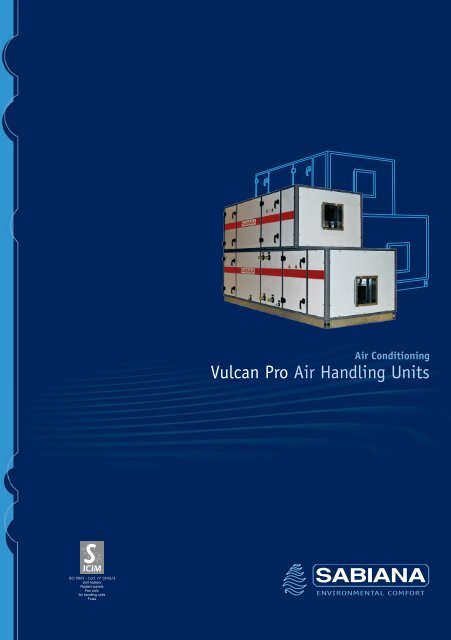
PresentationThe <strong>Vulcan</strong> <strong>Pro</strong> air handling units are built in compliance with the Europeanstandards and directives, and are designed to satisfy all design requirementsfor air-conditioning systems in which the reduction of noise levels, maximumair quality and minimum energy consumption are fundamental aspects inassessing the quality of the installation.The main defining feature of this new series concerns the special design ofthe aluminium sections that make up the structure, aimed at creating perfectlysmooth inside walls, without gaps or protrusions, so as to simplify cleaningand allow access to the components from the side.The basic configuration sees sandwich panels in two nominal thicknesses,35 and 50 mm, with the outside surface made from painted galvanised plateand the inside surface galvanised plate, with high density polyurethane foamthermal insulation in between, making the unit suitable for indoor and outdoorinstallation.The variants of the basic configuration include stainless steel or Peralumaninside panels, Peraluman outside panels and mineral wool insulation so asto guarantee maximum safety in the event of fires (no toxic gases are released),with effective soundproofing.The constructional versatility and the wide range of components allow technicaland dimensional solutions that can respond to any need.The systems are available as packaged units or a series of modular components,in a horizontal arrangement, with twooverlying levels, or in a verticalarrangement.The structure of the base, made fromthick galvanised plate section bars,guarantees maximum stability anduniform weight distribution.Centrifugal fans are normally usedin all versions: forward curved, backwardinclined or plug fans.All the electric motors can also beinverter-drivenThe heat exchange coil can be builtto handle different heat carrier fluids,such as: hot, superheated or chilled water, steam,ethylene glycol mixes, halogenated refrigerants, etc., oralternatively can be electrically powered.The air filters, the heat recovery units, the humidification systems and all theother components are selected or developed based on the latest technology.The extensive range of performance, the vast availability of components andaccessories, the multiple constructional variants featured for both the standardand custom configurations, and the high quality of the materials used makethis series of units, in terms of value-for-money, some of the most reasonablypriced and appealing on the market.3
Range650 - 350500 - 300400 - 300350 - 250300 - 200250 - 175200 - 150200 - 125175 - 100125 - 100125 - 75650 - 400550 - 350450 - 300400 - 250300 - 250250 - 200250 - 150175 - 150175 - 125150 - 100100 - 100100 - 75100908070605040302520151098765432<strong>Air</strong> flow-rate (m 3 /h x 1000)The <strong>Vulcan</strong> <strong>Pro</strong> air handling units areavailable in 23 sizes that can be easilyselected using the diagram shown on theside, based on the air velocity throughthe heat exchange coil.To simplify selection, it must be stressedthat in both the cooling/dehumidificationand heating/humidification processes, thecorrect air velocity is essential to avoidentraining water.It is therefore recommended to use thedroplet separator for humidification anddehumidification processes when the airvelocity exceeds 2.5 m/sec.In the humidification and cooling/dehumidification processes, the maximumvelocity of 2.8 m/sec should not beexceeded.3 2.5<strong>Air</strong> speed (m/sec)12Selection softwareSABIANA has developed software for selecting and quoting the <strong>Vulcan</strong> <strong>Pro</strong>air handling units, containing all the functions for choosing, calculating andsizing the components.This tool allows the system to be configured and sized based on the designrequirements, and analyses the performance in a simple and intuitive manner.Once having chosen the model, all the components selected are automaticallysized; the units can be selected with an in-line, stacked or vertical arrangement.By choosing the materials and based on the configuration, the program canprovide an immediate quotation, saving and printing the report if needed.SABIANA’s extensive experience with these types of units has allowed thecreation of templates with numerous configurations, including the most commonones that can be used as the basis for quickly configuring a design andquotation.4
CasingThe casing of the <strong>Vulcan</strong> <strong>Pro</strong> units is made up as follows:• load-bearing frame made from extruded aluminium alloy sectionbars, natural colour.• joints made from reinforced nylon (35 mm thick) and castaluminium (50 mm thick).• sandwich panels available in two nominal thicknesses, 35 and50 mm, made from the followingmaterials:- standard: outer: paintedgalvanised plate,“old iron” white/greycolour, C21.inner: galvanisedplate.insulation: injectedpolyurethane, density 45 Kg/m 3 .- upon request: outer: AISI 304 stainless steel - Peralumaninner: painted galvanised plate - AISI 304stainless steel - Peraluman.insulation: mineral wool, density 90 Kg/m 3 .- assembly: using galvanised steel self-threading screws, withNeoprene self-adhesive gaskets inserted betweenthe sections and the panels.The panels with mineral wool insulation areassembled using screws in bushes.• casing strengthSPECIFICATIONS OF THE CASINGACCORDING TO EN 1886• casing air leakage at -400 Pa• casing air leakage at +700 Pa• filter bypass leakage• thermal transmittance• thermal bridging factorFrequencyHz1252505001K2K4K8KSOUND ATTENUATIONdB 11,0dB 9,0dB 11,0dB 12,0dB 15,0dB 27,0dB 34,0D1L1L1F9T3TB335 mm and 50 mmthick panelswith polyurethane• access doors: same construction as the panels, fittedwith reinforced nylon hinges and painted aluminiumlocking device, Allen key housing socket, completewith sealing gasket, safety switch for the fan sectionsand, upon request, fitted with inspection window.For the sections with high inside pressure (e.g. fansections with plug fans or with absolute filters), thedoors are completely removable and fixed with barsand screw knobs.• floor panels: made with galvanised plate “C” bars,fitted with eyebolts for hoisting, arranged around theperimeter of each section (with the sole exception ofthe sections with washers, where the tray is used asthe floor support).5
<strong>Air</strong> intake sectionsThe air intake may be on the front across the entire section, or alternatively partially, on the sides, the top orbottom.The opening can be fitted with a damper positioned outside or inside the unit and/or vibration-damping joints.In outdoor installations, the rear or side direct air intake openings can also be fitted with weather louver and birdscreen.Mixing boxesFeaturing openings arranged in various positions as described above, fitted with dampers positioned outside orinside the unit and/or vibration-damping joints.DampersCounter-rotating louvers with connection flanges, available in thefollowing versions:• galvanised plate or aluminium with louvers connected by metal levers• aluminium with louvers connected by plastic cogs• aluminium with aerodynamic louvers and sealing gasketThe dampers always come with shafts for control levers, servo controlor manual control.GrillsThe direct intake openings or dampers on the units installed outdoorscan be fitted with an aluminium or galvanised steel grill with fixedhorizontal louvers to protect against the weather, plus bird screen.Vibration-damping jointsBuilt using galvanised plate section bars forming the connection flanges,joined at the corners with perforated brackets, these are made fromspecial fabric treated to be flame retardant, washable and rot-resistant.Sections with three dampersSections fitted with three dampers, respectively for the discharge, recirculation and intake of fresh outside air.The discharge and outside air intake dampers can be installed outside or inside the unit, at the top (vertical air flows)or alternatively on the sides, either on the same side or on opposing sides (horizontal air flows).The ambient air recirculation damper is always positioned inside, between the other two dampers.In installations with air handling units located outdoors and fitted with weather canopy, the discharge and direct airintake openings are located on the sides, and can be fitted with weather louver and bird screen.This section is normally used in systems with variable occupancy, allowing the quantity of fresh air intake to beadjusted in proportion to actual requirements.The three dampers can also be adjusted to allow freecooling when cooling is required in mid-seasons due to highinside thermal loads.6
Heat recovery sectionsThe heat recovery sections can be used with two types of heat exchanger:• cross flow plate heat exchanger.• heat wheel with opposing air flows.Plate heat exchangersSupplied as standard in the aluminium version, also available in the protectedversion with acrylic treatment when used in aggressive atmospheres.The section housing the exchanger can operate as a chamber withthree dampers, including, alongside of the heat recovery unit, arecirculation damper positioned is described in the following diagrams.The heat recovery unit can also be fitted with a bypass damper toallow freecooling operation.Heat wheelsThese are made up of a cylindrical rotor containing thousands of channelswith a large surface area, a galvanised steel support frame complete withbrush gaskets, and an actuator system consisting of an electric motor fitted,based on requirements, with a speed controller and control panel.Heat exchange occurs by accumulating heat in the wheel, which then transfersit, when rotating, from one flow of air to the other.The cylindrical rotor, in the standard version, is made entirely from aluminium,however it can also be chosen, using the calculation program, in the versionwith hygroscopic treatment for the purpose of increasing the efficiency of thedevice to exchange both heat and moisture between the two flows.The current EN 13779 standard requires filtration with minimum class F6 efficiency on the two air flows enteringthe heat recovery units, so as to keep the heat exchanger clean and efficient at all times.7
Filter sectionsThe air filters can use various types of filter materials, selected based on the classification determined by theEuropean standard EN 779 for medium and high efficiency, and EN 1822 for absolute filtering.Synthetic corrugated filtersClass G4 filters (average efficiency 90%), 48 and 98 mm thick, inserted onguides for removal from the side.The filtering media is made from synthetic fibre, housed in a galvanised plateframe with welded galvanised wire protection mesh.These can also be used as pre-filters for other higher efficiency filters; in thiscase, assembly is performed using special frames with fastening clips andremoval from the front.The filters are partially regenerable.Metal corrugated filtersClass G2 filters (average efficiency 72%), 48 and 98 mm thick, with a similarconstruction to the model described above, however with filtering media madefrom aluminium mesh.Normally used as pre-filters on the outside air intake in units installed in humidand foggy climates.The filters are highly regenerable.Non-rigid bag filtersFilters with sewn fibreglass bags, available in class F6 (averageefficiency 70%), F8 (average efficiency 92%) and F9 (averageefficiency 95%), 535 mm in length, inserted in a special frame withsealing gasket and fastening clips, designed for removal from the front.The filters are not regenerable.Rigid bag filtersPolyhedral rigid bag filters with pleated fibreglass paper media, availablein class F6, F8 or F9, 290 mm in length, with plastic supports, inserted in aspecial frame with sealing gasket and fastening clips, designed for removalfrom the front.The filters are not regenerable, and are completely incineratable.The bag filters described above,with class F8 or F9 efficiency, are always used as pre-filters for the absolute filters.8
Filter sectionsAbsolute filtersClass H13 (efficiency 99.95%) or class H14 (efficiency 99.995%) filters, pleatedglass paper media housed in a treated wooden frame, thermoplastic sealantand elastomer gasket, designed to be fitted in a special metal frame fixed bytension rods, with removal from the front.These filters are normally positioned downstream from the supply fan in theair handling unit, and always represent the final treatment before the air isdelivered into the environment.The filters are not regenerable.Roll filtersAutomatic roll filters with class G4 synthetic fibre media (average efficiency90%).Complete with electric gear motor, differential pressure switch to automaticallyadvance the dirty filter media, limit switch to signal the depleted filter mediaand electrical control panel.Can be selected starting from size 175-125.Activated carbon filtersThe activated carbon filters are available in two versions:• polyhedral with dimensions and assembly frame similar to therigid bag filters• cylindrical cartridge filters to be fitted, with sealing gasket, on aspecial metallic frame with bayonet fastening.The polyhedral filters, class F7 (average efficiency 80-85%) aresuitable for both filtration and deodorisation, and always requireminimum class G4 pre-filtration.They are not regenerable.9
Humidifier sectionsThe following humidification systems can be used:• wick (100 or 200 mm thick) with:- once-through water- recirculated water with external pump (up to size 250-175)with connections (as in the picture below)- recirculated water with internal pump with integral water circuit• self-cleaning spray nozzles with:- single rack for once-through water- single rack with recirculating pump- double rack with recirculating pump• atomised water with:- compressed air- Humifog system• steam with:- centralised supply- stand-alone immersed electrode humidifierDemineralised water must always be used.The droplet separators can be made:- entirely from galvanised plate,from aluminium or from stainless steel- with a galvanised, aluminium ora stainless steel frame and PVC separator elementsThe water collection trays can be made from galvanised or stainless steel andare fitted with all the required threaded connections.Upon request the access doors on the sections with nozzles can be fitted withinspection windows.EFFICIENCY AND WATER CONSUMPTIONOF WICK HUMIDIFIERSWick humidifier with once-through waterAdiabatic humidification using treated paper wetted mediawith a honeycomb structure, 100 and 200 mm thick, suppliedwith once-through water, complete with galvanised plate orAISI 304 stainless steel tray, droplet separator and threadedfittings for the water supply and drain.Wick humidifier with recirculated waterE (%)100908070602 2.5 30.1V (m/sec)P. 200P. 100Humidifier as described above, fitted with recirculatingwater pump, complete with stainless steel strainer, refillfloat valve, flow adjustment valve, droplet separator andtray with threaded fittings for refill, overflow and drain.R (l/h / m 3 /h)0.05P. 200P. 10002 2.5 3V (m/sec)E = Saturation efficiencyR = Water consumption ratio: R x m 3 /h = l/hV = <strong>Air</strong> speed10
Humidifier sectionsSpray nozzles with once-through waterDouble chamber humidifier with single rack of self-cleaning PVC atomisingnozzles, in counterflow direction to the air, galvanised or stainless steel platetray, droplet separator and threaded supply and drain fittings.Spray nozzles with recirculated waterDouble chamber humidifier with optional second access door, one or tworacks (air washer) of self-cleaning PVC atomising nozzles, arranged boththe same direction as the air and in counterflow, galvanised or stainless steelplate tray, flow straightener and splash at the inlet and droplet separator atthe outlet, recirculating pump with stainless steel strainer, refill float valve,flow adjustment valve and threaded supply, drain and overflow fittings.Atomised water with compressed airMade up of a rack of self-cleaning AISI 316 stainless steel atomising nozzlesin counterflow direction to the air, on-off or modulating control cabinet, dropletseparator and tray.Atomised water with Humifog systemMade up of a rack of self-cleaning AISI 316 stainless steel atomising nozzlesin the same direction as the air flow, housed in a stainless steel frame, controlcabinet with motor-driven pump to pressurise the water, and tray.Centralised steamMade up of one or more stainless steel linear steam distributors, sized forthe required flow-rate, fitted with condensate recovery hose, complete withdroplet separator and tray.Steam from stand-alone immersed electrode humidifierMade from stainless steel steam distributor pipes with condensate recovery,immersed electrode steam generator with production proportional to requirements,complete with modulating electronic controller accepting a proportional signalfrom an external controller (supplied upon request) and power circuit.The section is complete with droplet separator and tray.11
Heat exchange sectionsThe heat exchange sections contain the coils thatcan operate:• with hot, chilled or superheated water• with steam• with refrigerantsin expansion or condensation• electricallyHot or chilled water coilsMade from finned copper tubes with spacer collars, steel manifolds with threadedfittings and air vent and drain screws, galvanised plate frame.The finned heat exchanger can be arranged in steps of 2 - 2.5 - 3 and 4 mm,and made from the following materials: • aluminium • painted aluminium• copper • tinned copperThe copper tubes have a diameter of 5/8” (16.45 x 0.4 mm) and come in thefollowing shapes: • P60 = 60 x 30 mm• P40 = 40 x 30 mm• P30 = 30 x 30 mm with 1 to 12 rows.In some cases, different shapes are available, with 1/2” or 3/8” copper tubes.Superheated water or steam coilsThese can be made from 5/8” copper tubes, selected, in the calculationprogram, up to 0.75 mm thick for superheated water, or alternatively with steeltubes for steam.The other features concerning the shape and the finned heat exchanger aresimilar to those previously described for hot or chilled water.The manifolds can be fitted with PN10 or PN16 flanges.Refrigerant coilsThese are designed for expansion or condensation, with the same constructionalcharacteristics as regards the tubes, the shapes and the finned heat exchangeras the hot or chilled water coils described previously.The manifolds are made from copper with smooth welded fittings, while theexpansion coils come with a brass distributor on the gas inlet side.Electric heatersThe electric coils are made from steel pipe immersion heaters with continuousspiral fins, each fitted with ceramic isolators at the heads, and connectedtogether by brass plates.The frame is made from galvanised plate, with perimeter fastening flangesand junction boxes at the side with cable glands and access openings tothe connections.Available for single-phase or three-phase power supply.12
Fan sectionsThe fan sections can consist of different types of fans, which must be selected and sized based on the flow-rate,the static pressure, the noise generated and the efficiency.The latter is fundamental as regards the power of the electric motor and the corresponding energy consumption.In general, all the fan assemblies are fitted on a galvanised steel support structure, in turn fixed via elastomer vibrationdamping joints to a second base structure secured to the load-bearing frame of the casing.All the fan outlets are joined to the panels via vibration damping joints, the access doors are always fitted with safetymicro-switched and can, upon request, have inspection windows.The transmission is made from a number of suitably sized V-belts according to the power transferred, and the pulleysare always fitted with Taperlock bushes.The motors are Unel Mec brand with class F insulation, IP 55 protection and class EFF2 energy rating (EFF1 uponrequest), fitted on slides or alternatively, for the plug fans, directly coupled to the rotor and suitable for inverter drive.Motors with ratings higher than 7.5 kW must always feature star-delta starting.Upon request, the sections can feature lights on the inside.Forward curved centrifugal fansDual intake with galvanised steel screw and impeller, dynamically and staticallybalanced, fitted on steel shafts supported by pre-lubricated sealed bearings,ideal for low and medium pressure.Backward inclined centrifugal fansDual intake with galvanised steel chassis and screw, welded and paintedsteel impeller (polyamide for the smaller sizes), dynamically and staticallybalanced, fitted on steel shafts supported by pre-lubricated conical bearings,suitable for systems with medium and high static pressure that require goodefficiency.Backward inclined centrifugal fans with airfoil bladesDual intake with galvanised steel frame and screw, welded and painted steelimpeller, dynamically and statically balanced, fitted on steel shafts supportedby bearings on cast-iron supports with lubricator, especially suitable whenhigh efficiency is required with high static pressure.Plug fansSingle intake with backward inclined impeller and directly coupled motorsuitable for inverter drive.The casing of the section, replacing the fan screw, is always in positive pressure.Therefore, to ensure the seal, all the panelling is sealed on the inside and theaccess doors are totally removable and fastened, using reinforcement bars,by screw knobs.13
Silencer sectionsMade from a series of 100 mm thick layers of sized mineral wool, arranged in the direction of air flow, spaced 100 mmapart, normally positioned at the inlet and/or outlet of the handling unit to reduce the noise generated by the fans.The graph indicates the attenuation value in dB for the standard silencers (available in the three lengths, 900 - 1200and 1500 mm) to be subtracted from the noise generated by the chosen fan and indicated by the selection program,thus calculating the overall noise transmitted in the air ducts connected to the unit.The silencer should be positioned a minimum distance apart from the preceding or following equal to around the netheight inside the unit and, if installed after the fan, the latter must be fitted with a flow equalizer on the outlet.OCTAVE BAND ATTENUATION dBWITH DISTANCE BETWEEN LAYERS = 1006051 53 39ATTENUATION dB50403020105 6 8 915121626233043403951 53314145322926L = 1500L = 1200L = 900063 125 250 500 1000 2000 4000 8000FREQUENCY HzMulti-zone or dual duct sectionsThese sections, always positioned “downstream” from the supply fan (fittedwith flow equalizer), are made up of a cooling coil with condensate collectiontray, a post-heating coil with a reduced cross-section and one or more twosectiondampers with opposing movement, to be motor driven, sized basedon the air flow-rates of the various zones being served.The section is divided into two separate sectors, with “hot” and “cold” air flowsthat will be mixed at the outlet of each zone damper based on the requirementsignalled by the local control thermostat.In dual duct systems, there are just two outlets, “hot” and “cold”, which supplyvarious mixing terminal units located in the room.PlenumsAvailable in three lengths, around 300, 600 and 900 mm, for the formationof plenums or housing components supplied by the Customer.14
Automatic controlThe <strong>Vulcan</strong> <strong>Pro</strong> air handling units can be supplied complete with power andcontrol electrical panel, with the lines prepared and marked for connection todevices that are not supplied (such as temperature control valves, thermostats,humidistats, etc.) and connections already made to the fan motors, safetyswitches on the access doors, any lights inside the sections, and any servocontrols on the dampers.The electrical panel, made from a metal box with IP 55 protection, normallyfeatures: a microprocessor controller plus terminal with buttons and displayfor reading the parameters, indicator lights, main and door interlock disconnectswitch, contactors, motor protectors with thermal relays, protection fuses,autotransformer, terminal blocks and any other components that are requiredin compliance with the standards in force.A junction box with marked terminal block will be provided next to each devicethat requires connection on site.For the correct construction of the electrical system, always refer to thetechnical specifications and the wiring diagrams for all the temperaturecontrol components featured.RSTVR1211PSEBC4 3 5BFSAUM6VMSLLegend:ST = temperature probesSU = humidity probeSL = supply limit probeSA = anti-freeze probeSE = outside air probeR-1/6 = controllers and servo motorsBC = heating coilBF = cooling coilUM = humidifierP = differential pressure switchVR = return fanVM = supply fanROOMSUAccessoriesThe following accessories can be supplied upon request:• Weather canopy for outdoor installation, made from painted galvanisedsteel or aluminium.• Utility compartment containing the temperature control devices, normallyinstalled on the opposite side to the filter and fan section inspectionopenings, covering the same length as the entire unit or limited to the airhandling section, depth around 600 mm, complete with access doors.• Lights inside the sections fitted with access door plus inspection window,wired to the switch on the outside.• Differential air pressure gauge to signal dirty filters.• Motor drive inverter.• <strong>Pro</strong>tective guard on the transmission.15
Positioning some of the componentsDiagram A represents a unit with two air supply and return fans, oneon top of the other, plus a heat recovery section fitted with a bypassdamper between the return fan and the heat recoveryunit to allow operation with a proportionally variable quantity ofdischarge air (e.g. to the level of occupancy).The return air can in fact be totally or partially recirculated using thisdamper and, as a consequence, totally or partially discharged afterflowing through the heat recovery unit.To balance the air circuit, this alternating air flow must occur withoutdifferences in pressure drop, therefore, as the pressure drop is higherthrough the heat recovery unit, the bypass damper will be equippedis such a way as to be able to balance the resistance, for exampleusing perforated metal plates or a second overlapping damper withfixed calibration.Diagram ADiagram B, on the other hand, represents the same type of unit in whichoperation features total discharge of the return air and recirculationonly when the system has yet to reach steady operating conditions,that is, when the air-conditioned rooms are not yet occupied.Modulating operation similar to the above would cause a reductionin heat recovery efficiency during intermediate operation.In this case, the bypass damper is positioned after the heatrecovery unit and no additional pressure drop will need to be created,as the air circuit, in both situations, will always be balanced.In this configuration, by temporarily activating operation with totalrecirculation, defrosts can be implemented when the conditionsrepresent the risk of frost forming at the inlet to the heat recovery unit.These figuresindicate the different positionsof the fan outlets,which can be selectedin the program based on the directionof the connection ducts.Diagram BThe diffuser that joinsthe fan outlet to the ductmust have a length (L) such thatthe joint has an angle of around 15°.17
<strong>Air</strong> Conditioning<strong>Vulcan</strong> <strong>Pro</strong> <strong>Air</strong> <strong>Handling</strong> <strong>Units</strong>UTA - 01/09COD. A4190100 A/01/09ENVIRONMENTAL COMFORTSabiana s.p.a. • via Piave, 53 • 20011 Corbetta • Milano • Italy • phone +39.02.97203.1 r.a. / +39.02.97270429 / +39.02.97270576fax +39.02.9777282 / +39.02.9772820 • www.sabiana.it • info@sabiana.it