ELFOSPACEBOX 2 7-41 - BTK
ELFOSPACEBOX 2 7-41 - BTK
ELFOSPACEBOX 2 7-41 - BTK
- No tags were found...

Create successful ePaper yourself
Turn your PDF publications into a flip-book with our unique Google optimized e-Paper software.
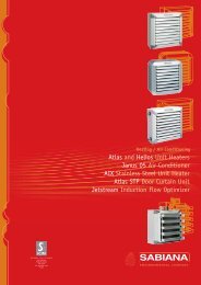
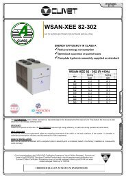
BT07C006GB-01(EC1)REPLACE: BT07C006GB-01TERMINALS7 - <strong>41</strong>®<strong>ELFOSPACEBOX</strong> 2 7-<strong>41</strong>"CASSETTE" TYPE TERMINAL UNIT<strong>ELFOSPACEBOX</strong> 2 7 - <strong>41</strong>SizeCoolingHeating[kW][kW]7 2,84 3,1011 4,62 5,1215 5,38 5,8621 6,58 7,2631 10,1 11,1<strong>41</strong> 11,9 13,2Innovative and fascinating design, six different models, great flexibility of control and adjustment, easy maintenance: the new ElfoSpaceBox2 box fan coil unit is the result of technical and style research aimed at offering an advanced product in terms of performance, silence,and flexibility of adjustment.The air intake and diffusion grille has a very elegant appearance, absolutely innovative, able to ensure excellent air flow performancethanks to in-depth computer studies and laboratory testing. The standard colour is white RAL 9003.The dimensions of the first 3 sizes comply with the 600x600 mm modular design of false ceilings, while the larger sizes, measuring800x800 mm, focus on silent operation and the price/performance ratio of these great models.CERTIFIED QUALITY SYSTEM UNI EN ISO 9001:2008
BT07C006GB-01(EC1)TERMINALS7 - <strong>41</strong>ELECTRICAL DATAVoltage: 230/1/50Size 7 11 15 21 31 <strong>41</strong>F.L.A. - FULL LOAD CURRENT AT MAX ADMISSIBLE CONDITIONSF.L.A. - Total A 0,2 0,3 0,5 0,4 0,5 0,7F.L.I. FULL LOAD POWER INPUT AT MAX ADMISSIBLE CONDITIONF.L.I. - Total kW 0,044 0,068 0,09 0,077 0,12 0,17OPERATING LIMITS (COOLING)Size 7 11 15 21 31 <strong>41</strong>Min. water inlet temperature °C 5 5 5 5 5 5Maximum water side pressure bar 8 8 8 8 8 8Max air temperature inlet (WB) °C 40 40 40 40 40 40Max ambient relative humidity % 75 75 75 75 75 75Min ambient relative humidity % 15 15 15 15 15 15Min air inlet temperature (W.B.) °C 6 6 6 6 6 6Max water inlet temperature °C 80 80 80 80 80 80ELECTRIC HEATERSSize 7 11 15 21 31 <strong>41</strong>1,5 kW X - - - - -3 kW - X X - - -4 kW - - - X X XAIR FLOW / FAN SPEEDSize 7 11 15 21 31 <strong>41</strong>Air flow (minimum speed) l/s 86 89 119 175 197 197Air flow (medium speed) l/s 117 139 169 228 269 356Air flow (maximum speed) l/s 144 197 244 317 <strong>41</strong>7 506Corrective coefficients for yield based on air flow rate2 pipe systemELFOSPACE BOX27 ( 2T ) 11 ( 2T ) 15 ( 2T ) 21 ( 2T )31 ( 2T ) <strong>41</strong> ( 2T )V L M H L M H L M H L M H L M H L M HKf 0.69 0.86 1 0.54 0.77 1 0.59 0.76 1 0.65 0.79 1 0.56 0.72 1 0.48 0.77 1Ks 0.67 0.85 1 0.52 0.75 1 0.56 0.75 1 0.63 0.78 1 0.54 0.70 1 0.46 0.75 1Kt 0.67 0.85 1 0.52 0.76 1 0.53 0.69 1 0.63 0.78 1 0.53 0.70 1 0.46 0.75 1High speed (H)Medium speed (M)Low speed (L)KF = cooling performance multiplication coefficientKs= sensible output multiplication coefficientKt = heating performance multiplication coefficientCorrective coefficients for yield based on air flow rate4-pipe systemELFOSPACE BOX27 ( 4T ) 11 ( 4T ) 15 ( 4T ) 21 ( 4T )31 ( 4T ) <strong>41</strong> ( 4T )V L M H L M H L M H L M H L M H L M HKf 0.69 0.86 1 0.55 0.77 1 0.60 0.77 1 0.64 0.78 1 0.57 0.72 1 0.50 0.78 1Ks 0.67 0.85 1 0.53 0.76 1 0.58 0.76 1 0.63 0.77 1 0.55 0.71 1 0.47 0.76 1Kt 0.70 0.87 1 0.59 0.79 1 0.63 0.79 1 0.65 0.79 1 0.61 0.75 1 0.54 0.80 1High speed (H)Medium speed (M)Low speed (L)KF = cooling performance multiplication coefficientKs= sensible output multiplication coefficientKt = heating performance multiplication coefficient4
BT07C006GB-01(EC1)TERMINALS7 - <strong>41</strong>AIR EXHAUSTThe air launch indicated in the tables must be considered only as an guideline, since it may vary substantially based on the size of the room where the unit is installedand the arrangement of furniture in the room.The useful launch L refers to the distance between the unit and the point at which the air has a speed of 0.2 m/sec; if the fin is inclined at 30° (advisable duringcooling phase, there is the so-called "Coanda" effect as shown in the first graph, whereas with an inclination of 45° (suggested in heating phase) there is a launchdownwards as illustrated in the second graph.ELFOSPACE BOX 27 11 15 2131 <strong>41</strong>V 1 (L) 2 (M) 3 (H) 1 (L) 2 (M) 3 (H) 1 (L) 2 (M) 3 (H) 1 (L) 2 (M) 3 (H) 1 (L) 2 (M) 3 (H) 1 (L) 2 (M) 3 (H)L (m) 3.0 3.5 3.8 3.0 3.8 4.5 3.5 4.2 5.0 3.2 3.7 4.3 3.4 4.0 5.0 3.4 4.6 5.5ELFOSPACE BOX 27 11 15 21 31 <strong>41</strong>V 1 (L) 2 (M) 3 (H) 1 (L) 2 (M) 3 (H) 1 (L) 2 (M) 3 (H) 1 (L) 2 (M) 3 (H) 1 (L) 2 (M) 3 (H) 1 (L) 2 (M) 3 (H)L (m) 3.3 3.9 4.2 3.3 4.2 4.8 3.9 4.5 5.2 3.5 4.1 4.8 3.8 4.6 5.4 3.8 5.1 5.8H (m) 2.2 2.6 2.8 2.2 2.8 3.2 2.6 3.0 3.4 2.2 2.6 3.0 2.4 2.8 3.4 2.4 3.1 3.6B (m) 2.5 2.9 3.1 2.5 3.1 3.6 2.9 3.4 3.9 2.7 3.2 3.8 3.0 3.6 4.2 3.0 4.0 4.6In winter sizing, use special care with buildings in which floor temperature is very low (for example lower than 5°C). In this situation, the air above the floor may becooled to temperatures that are so low that they contrast the even diffusion of warm air coming out of the unit, thus reducing the launch value indicated in the table.6
BT07C006GB-01(EC1)TERMINALS7 - <strong>41</strong>COOLING PERFORMANCESizeTa(°C)DB/WB2 PIPESEXTERNAL EXCHANGER WATER INLET / OUTLET TEMPERATURE (ºC)6 / 11 7 / 12 9 / 14 10 / 15 13 / 18kWf kWs kWf kWs kWf kWs kWf kWs kWf kWs71115213122 / 15,424 / 1726 / 18,627 / 19,528 / 20,330 / 21,922 / 15,424 / 1726 / 18,627 / 19,528 / 20,330 / 21,922 / 15,424 / 1726 / 18,627 / 19,528 / 20,330 / 21,922 / 15,424 / 1726 / 18,627 / 19,528 / 20,330 / 21,922 / 15,424 / 1726 / 18,627 / 19,528 / 20,330 / 21,922 / 15,424 / 171,76 1,60 1,57 1,48 1,23 1,23 1,08 1,08 0,71 0,712,26 1,84 2,00 1,72 1,55 1,47 1,36 1,35 0,90 0,902,81 2,06 2,52 1,94 1,99 1,69 1,75 1,57 1,18 1,183,15 2,16 2,84 2,04 2,28 1,79 2,03 1,67 1,37 1,313,45 2,26 3,14 2,14 2,57 1,90 2,30 1,78 1,56 1,424,10 2,48 3,81 2,36 3,23 2,12 2,93 2,01 2,01 1,652,82 2,53 2,54 2,34 2,01 1,96 1,78 1,77 1,16 1,163,70 2,91 3,28 2,71 2,54 2,33 2,22 2,14 1,47 1,474,61 3,25 4,11 3,06 3,23 2,68 2,85 2,48 1,92 1,915,13 3,<strong>41</strong> 4,62 3,22 3,69 2,84 3,28 2,65 2,23 2,085,60 3,57 5,09 3,38 4,15 3,00 3,71 2,82 2,55 2,256,56 3,91 6,10 3,72 5,18 3,35 4,71 3,16 3,28 2,603,29 2,99 2,97 2,77 2,37 2,31 2,09 2,09 1,36 1,364,31 3,44 3,82 3,21 2,97 2,76 2,60 2,53 1,72 1,725,36 3,84 4,79 3,61 3,77 3,16 3,32 2,94 2,24 2,245,98 4,02 5,38 3,80 4,30 3,35 3,82 3,13 2,60 2,466,54 4,22 5,94 3,99 4,83 3,55 4,32 3,33 2,97 2,667,69 4,61 7,14 4,40 6,03 3,96 5,48 3,74 3,82 3,084,02 3,63 3,59 3,36 2,82 2,81 2,48 2,48 1,64 1,645,27 4,17 4,66 3,89 3,59 3,35 3,14 3,07 2,09 2,096,56 4,65 5,85 4,38 4,60 3,83 4,05 3,56 2,72 2,727,30 4,88 6,58 4,60 5,27 4,06 4,67 3,79 3,16 2,987,97 5,11 7,25 4,84 5,92 4,30 5,30 4,03 3,60 3,229,33 5,59 8,70 5,33 7,40 4,80 6,73 4,53 4,63 3,736,29 5,51 5,59 5,10 4,36 4,29 3,83 3,83 2,58 2,588,14 6,31 7,23 5,90 5,62 5,08 4,92 4,68 3,23 3,2310,1 7,05 9,04 6,64 7,18 5,82 6,34 5,42 4,21 4,1911,2 7,40 10,1 6,99 8,20 6,18 7,30 5,77 4,90 4,5512,2 7,75 11,2 7,35 9,18 6,54 8,24 6,13 5,60 4,9214,2 8,49 13,3 8,09 11,4 7,29 10,4 6,88 7,24 5,687,38 6,55 6,58 6,06 5,16 5,08 4,53 4,53 3,03 3,039,56 7,50 8,48 7,02 6,59 6,04 5,77 5,55 3,83 3,83<strong>41</strong>26 / 18,627 / 19,528 / 20,330 / 21,911,8 8,37 10,6 7,89 8,<strong>41</strong> 6,92 7,43 6,43 4,98 4,9713,1 8,78 11,9 8,30 9,60 7,33 8,55 6,85 5,78 5,4014,3 9,20 13,1 8,72 10,8 7,76 9,65 7,28 6,59 5,8316,8 10,1 15,7 9,59 13,4 8,64 12,2 8,17 8,47 6,74The performance refers to rated air flow.Ta = air intake temperatureDB = dry bulbWB = wet bulbkWf = Cooling capacity in kWkWs = sensible cooling capacity (kW)7
BT07C006GB-01(EC1)TERMINALS7 - <strong>41</strong>2 PIPESHEATING PERFORMANCESizeTa (°C)AIR INLET TEMPERATURE40 50 55 60 70 80kWt kWt kWt kWt kWt kWt711152131<strong>41</strong>101518202225101518202225101518202225101518202225101518202225101518203,14 4,51 5,19 5,87 7,23 8,592,45 3,79 4,46 5,14 6,49 7,842,03 3,37 4,04 4,72 6,06 7,401,75 3,10 3,77 4,44 5,78 7,101,47 2,83 3,50 4,17 5,50 6,811,05 2,43 3,11 3,78 5,10 6,385,20 7,39 8,48 9,57 11,7 13,94,09 6,24 7,31 8,38 10,5 12,73,<strong>41</strong> 5,56 6,63 7,70 9,84 12,02,96 5,12 6,19 7,26 9,39 11,52,50 4,68 5,76 6,83 8,94 11,01,81 4,04 5,13 6,20 8,30 10,35,90 8,42 9,68 10,9 13,4 15,94,63 7,14 8,38 9,62 12,1 14,53,86 6,37 7,61 8,85 11,3 13,73,34 5,86 7,10 8,33 10,8 13,12,82 5,35 6,59 7,82 10,2 12,62,03 4,58 5,83 7,07 9,48 11,87,36 10,5 12,1 13,6 16,7 19,85,77 8,85 10,4 11,9 15,0 18,14,82 7,89 9,43 11,0 14,0 17,14,17 7,26 8,80 10,3 13,4 16,43,53 6,64 8,18 9,71 12,7 15,72,55 5,71 7,27 8,80 11,8 14,811,2 15,8 18,1 20,4 25,0 29,68,82 13,4 15,7 18,0 22,5 27,07,39 12,0 14,3 16,6 21,0 25,56,43 11,1 13,3 15,6 20,1 24,45,46 10,1 12,4 14,7 19,1 23,53,99 8,70 11,0 13,3 17,7 22,013,3 18,8 21,6 24,4 29,9 35,310,5 16,0 18,8 21,5 26,9 32,38,74 14,3 17,1 19,8 25,2 30,47,59 13,2 15,9 18,6 24,0 29,222256,43 12,0 14,8 17,5 22,8 28,04,68 10,3 13,1 15,8 21,1 26,3The performance refers to rated air flow.difference between inlet / outlet water temperature = 10°CTa = air intake temperaturekWt = Heating capacity (kW)8
BT07C006GB-01(EC1)TERMINALS7 - <strong>41</strong>COOLING PERFORMANCESizeTa(°C)DB/WB4 TUBESEXTERNAL EXCHANGER WATER INLET / OUTLET TEMPERATURE (ºC)6 / 11 7 / 12 9 / 14 10 / 15 13 / 18kWf kWs kWf kWs kWf kWs kWf kWs kWf kWs71115213122 / 15,424 / 1726 / 18,627 / 19,528 / 20,330 / 21,922 / 15,424 / 1726 / 18,627 / 19,528 / 20,330 / 21,922 / 15,424 / 1726 / 18,627 / 19,528 / 20,330 / 21,922 / 15,424 / 1726 / 18,627 / 19,528 / 20,330 / 21,922 / 15,424 / 1726 / 18,627 / 19,528 / 20,330 / 21,922 / 15,424 / 171,74 1,61 1,57 1,48 1,25 1,24 1,10 1,10 0,71 0,712,30 1,85 2,04 1,73 1,57 1,48 1,37 1,36 0,91 0,912,89 2,07 2,56 1,94 2,00 1,70 1,75 1,58 1,19 1,193,22 2,17 2,89 2,05 2,29 1,80 2,03 1,68 1,38 1,313,53 2,27 3,19 2,15 2,58 1,91 2,30 1,79 1,57 1,424,15 2,49 3,85 2,37 3,25 2,13 2,94 2,01 2,03 1,652,56 2,33 2,31 2,15 1,84 1,80 1,62 1,62 1,06 1,063,37 2,67 2,99 2,50 2,31 2,15 2,02 1,97 1,35 1,354,21 2,99 3,74 2,81 2,93 2,46 2,58 2,29 1,75 1,754,68 3,13 4,21 2,96 3,35 2,61 2,97 2,44 2,03 1,915,11 3,28 4,64 3,11 3,77 2,76 3,37 2,59 2,32 2,075,99 3,59 5,57 3,42 4,72 3,08 4,29 2,91 2,97 2,402,97 2,71 2,66 2,51 2,09 2,09 1,84 1,84 1,22 1,223,87 3,11 3,43 2,91 2,65 2,50 2,32 2,30 1,55 1,554,81 3,47 4,30 3,27 3,38 2,87 2,98 2,66 2,02 2,025,36 3,64 4,83 3,44 3,87 3,04 3,43 2,83 2,34 2,235,86 3,81 5,33 3,61 4,34 3,21 3,89 3,01 2,66 2,<strong>41</strong>6,89 4,17 6,<strong>41</strong> 3,98 5,43 3,58 4,93 3,38 3,<strong>41</strong> 2,794,14 3,71 3,69 3,43 2,89 2,88 2,54 2,54 1,69 1,695,42 4,26 4,79 3,99 3,70 3,43 3,23 3,15 2,14 2,146,73 4,76 6,01 4,48 4,73 3,93 4,17 3,65 2,79 2,797,49 4,99 6,76 4,72 5,42 4,16 4,81 3,89 3,25 3,058,17 5,23 7,45 4,96 6,09 4,<strong>41</strong> 5,45 4,13 3,70 3,309,57 5,73 8,93 5,46 7,60 4,92 6,91 4,65 4,77 3,835,80 5,17 5,16 4,78 4,03 4,01 3,54 3,54 2,37 2,377,52 5,94 6,66 5,55 5,16 4,77 4,51 4,38 3,00 3,009,32 6,64 8,35 6,25 6,60 5,47 5,82 5,08 3,91 3,9110,4 6,96 9,37 6,57 7,54 5,80 6,71 5,<strong>41</strong> 4,54 4,2511,3 7,30 10,3 6,91 8,46 6,14 7,58 5,76 5,18 4,6013,3 7,99 12,4 7,61 10,5 6,85 9,58 6,47 6,65 5,336,70 6,06 5,99 5,61 4,71 4,69 4,14 4,14 2,75 2,758,69 6,96 7,69 6,51 5,95 5,59 5,21 5,14 3,49 3,49<strong>41</strong>26 / 18,627 / 19,528 / 20,330 / 21,910,8 7,77 9,64 7,31 7,59 6,<strong>41</strong> 6,69 5,95 4,54 4,5<strong>41</strong>2,0 8,15 10,8 7,69 8,68 6,79 7,71 6,34 5,26 4,9813,1 8,53 12,0 8,08 9,75 7,18 8,73 6,73 5,99 5,3815,5 9,33 14,4 8,89 12,2 8,00 11,1 7,56 7,68 6,23The performance refers to rated air flow.Ta = air intake temperatureDB = dry bulbWB = wet bulbkWf = Cooling capacity in kWkWs = sensible cooling capacity (kW)9
BT07C006GB-01(EC1)TERMINALS7 - <strong>41</strong>PRIMARY AIR HANDLINGThe ELFOSPACE BOX2 box fan coil units can mix primary air with recirculation air. The maximum amount of external air is equal to 20% of the flow rate of the fancoil unit at medium speed. In any case from every corner it is possible to insert a maximum of100 m3/h.(1) AMBIENT AIR INTAKE(2) PRIMARY AIR(3) DISCHARGED AIRThe units can draw primary air in 3 of the four corners (the fourth is reservedfor condensation drainage). The inlet holes allow the use of standard rectangularducts110 x 55 mm or the adaptor for circular ducts shown below.Connection is very rapid and practical.(2) PRIMARY AIR(CONRX) FRESH AIR CONNECTIONThe fresh air flow for ELFOSPACE BOX2 cassette is limited to 20%of the total fan coil air flow at medium speed and 100 m3/h for each treated air inlet.The air duct is connected quickly and easily.After removing the blank and the insulation inside the unit,the mounting plate is rolled back and the air duct with its V-shaped sectionmust be pushed into the unit. The duct is then fixed to the mounting plate.Note: the fresh air must be filtered.11
BT07C006GB-01(EC1)TERMINALS7 - <strong>41</strong>(MAUXX)AUXILIARY AIR OUTLET FITTINGTwo air outlets are provided on the side of the unit for connection to separate supply air outlets.They can be used to supply air from the fan coil unit to distant areas of a room or even to a different room.The total air flow does not change. The air flow at high speed depending on the air duct pressure drop is shown in the tables below.Note: all air ducts must be insulated in order to avoid condensation.N. 1 used outletsdP = pressure dropQ = water flowN. 2 used outletsdP = pressure dropQ = water flowThis is used to introduce primary air into the environment directly throughthe diffuser. The kit includes a flow separator to be fitted inside thecassette, and a circular fitting for connection to the flexible system ducting.The flow of air is sent directly to just one of the outlet louvers, withoutpassing through the coil. The air flow of fresh air introduced into theenvironment depend on the inlet static pressure.7-11-15 21-31-<strong>41</strong>Ø 150 mmØ 180 mmQ m³/h Pa Q m³/h Pa80 3 160 3120 8 200 8160 15 300 15200 25 400 25240 36 500 3612
BT07C006GB-01(EC1)TERMINALS7 - <strong>41</strong>(2V2X)2-WAY ON/OFF VALVE 2-PIPE SYSTEM(3V2X)3-WAY ON/OFF VALVE 2-PIPE SYSTEM(2V4X)2-WAY ON/OFF VALVE 4-PIPE SYSTEM(3V4X)3-WAY ON/OFF VALVE 4-PIPE SYSTEMRated pressure:16 barMax. ambient temperature:50 °CMax. water flow temperature:110 °CPower:230 V - 50/60 HzRate:3 VAProtection:IP 43Travel time:ca. 3 min.Max. glycol content of water:50%Valve set, 2 or 3 ways, ON-OFF, with thermoelectric actuator.The set includes connection pipes and holders.Note: The main battery valve connection is 1/2” for 7-11-15 sizesand 3/4” for 21-31-<strong>41</strong>sizes,the auxiliary battery valve connection is 1/2”.Note: The maximum pressure drop accrossthe fully open valve should not exceed 25 kPafor cooling operation and 15 kPa for heating operation.Pressure dropCC2 - 2- PIPE SYSTEM COILCC4 - 4- PIPE SYSTEM COILA - MAIN COIL (COOLING)B - AUXILIARY COIL (HEATING)* - EXTERNAL THREAD** - MAX DIFFERENCE OF PRESSURE AT CLOSED VALVEDP = PRESSURE DROPQ = WATER FLOW13
BT07C006GB-01(EC1)TERMINALS7 - <strong>41</strong>(CIVX)FAIRING FOR IN-VIEW INSTALLATIONThe body for visible installation has been designed for all rooms in which false ceilings have not orcan not be provided in which to insert the mechanical and electrical systems.The covering cabinet matches perfectly with the air intake and delivery grille, conserving the designand charm that characterize the ElfoSpace Box2 series. Plumbing connections can be faced u-pwards.The series with a body for visible installation includes 6 models, with an installation height of up to 5m, thanks to the great versatility of adjustment of the air diffusion fins.All of the technical characteristics described in the previous pages remain valid, keeping in mindthat the series with body for visible installation has a single thermal exchange coil (2-pipe system),without the possibility of primary air or additional electrical battery.The version with body for visible installation includes a special covering packaged separately whichmust be applied only after the ElfoSpace Box2 has been installed with electrical and plumbingconnections complete.DIMENSIONAL DRAWINGseparately supplied accessories(E) EXCHANGER WATER INLET(U) EXCHANGER WATER OUTLET(UC) CABLE EXITCASING WEIGHT: 5 KG (7,5 KG WITH THEPACKAGING)Warning: the electrical and water connectionsmust enter the unit from above and must not interferewith the casing.CASING WEIGHT: 10,5 KG (13,5 KG WITHTHE PACKAGING)Warning: the electrical and water connectionsmust enter the unit from above and must notinterfere with the casing.(E) WATER INLET(U) WATER OUTLET(UC) ELECTRICAL CONNECTIONS OUTLET14
BT07C006GB-01(EC1)ACCESSORIESTERMINALS7 - <strong>41</strong>Standard electronic version(HID-E2X)HID-E2 Simplified room control S/W+3V+on/off for wall mountingHID-E2 electromechanical room thermostat for wall installation It allows:-setting of the desidered temperature (10-30°C)-selection of the 3 speeds (MIN - MED - MAX)-on/off-manual mode switching Summer / Winter-unbroken ventilation or controlled by a thermostat- on/off control for hot/cool water valve coil for 2 and 4 tube system controlled bya termostat. It can be connected to the remote air probeseparately supplied accessories(HID-E3X)HID-E3 Multi-function room control for wall mountingelectro-mechanical ambient thermostat HID-E3 for wall mounting It enables:-automatic fan speed adjustment (MIN - MED - MAX)-silent operation (fan min. speed)-on/off-ambient temperature control through control knob: the knob central positioncorresponds to the comfort setting (20°C in heating, 24°C in cooling), the temperaturecan be changed by +/- 5°C from the comfort condition by turning the knob-automatic selection of Summer/Winter season: the choice between heating andcooling is automatically made detecting the temperature of the outlet water atthe fan-coil (water temperature lower than 17°C=cooling operation, water temperaturehigher than 21°C=heating operation)-Hot start function: while heating the fan does not start unless the thermal coil issufficiently hot-destratification cycle-dirty filter signal-water min. temperature probe (supplied separately)-on/off control for hot/coolwater valve coil for 2 and 4 tube system controlled by a termostatDimensions: 184x82x27 mmseparately supplied accessories(PTABX)Remote probe for ambient air temperature for electromechanical thermostats.The remote room air sensor can be connected to the HID-E_ room thermostats complete with sensor input (HID-E1 excepted).Ambient air probe applicable to thermostat, cable lenght 1mseparately supplied accessories(DCPX)Control device for more units with a single room control.Control device from single HID-E_ room thermostat for max. 4 units for each DCPX.separately supplied accessories15
BT07C006GB-01(EC1)TERMINALS7 - <strong>41</strong>(CTS)CLIVET TALK TERMINAL electronic for HID-T2 or HID-T3 thermostats(ELFOControl)This is a card for control of the unit which, in addition to basic functions, allows it to be connected to a network ofsimilar units managed centrally by ELFOControl, which in turn can be connected to a supervisor, moreover it canalso manage a linked mini-net ,of maximum 8 units, by RS485 or Wireless serial ports, with a Master-Slave system.This type of electronic card is suited for communicating via RS485 or wireless if connected to SP1 or SPZB devices.The microprocessor control installed in the unit receives operating settings from one of the following devices:HID-T2 - room control for wall installationHID-T3 - room control for wall installation with humidity probe– ELFOControl Its functions are:- control of minimum temperature of system water temperature- manual or automatic control of fan speed- control of ON-OFF water valve- digital input for remote on/off function or winter/summer- control of fan / actuator of external air shutter- on/off control of electrical heating element or cumulative alarm relay. The room temperature probe includes theClivetTalkTerminalSpace electronics.optional accessory(HID-T2X)HID-T2 electronic ambient controlThe HID-T2 room thermostat makes it possible to interface with the regulation module of units equipped with Clivet-TalkTerminal Space electronics and to manage one or more thermostat units.The room thermostat allows the following functions:-Setting of desired temperature- Selection of the three speeds (MIN - MED - MAX) manually or automatically-On/off_ Change Summer/winter automatically or manually with digital input- Selection of economic operation-Setting of unit operation parameters-Setting of fan-only mode-Control of external air shutter and control of motorized air outlet grille, if present-Management of diagnostics with specific code for type of errorDimensions: 184X82X27 mmseparately supplied accessories(HID-T3X)HID-T3 electronic ambient controlThe HID-T3 room climate control makes it possible to interface with the regulation module of units equipped withClivetTalkTerminal Space electronics and to manage one or more thermostat units. The room thermostat allows thefollowing functions:-Setting of desired temperature- Selection of the three speeds (MIN - MED - MAX) manually or automatically-On/off- Change Summer/winter automatically or manually with digital input- Selection of economic operation-Setting of unit operation parameters-Setting of fan-only mode-Control of external air shutter and control of motorized air outlet grille, if present-Management of humidity probe-Humidity display-Management of diagnostics with specific code for type of errorDimensions: 184X82X27 mm The thermostat is connected to the unit by means of a shielded twisted pair at adistance of up to 15 m. For connections to the ELFOControl network, refer to the specific sections.separately supplied accessories(HID-TI2X)HID-TI2 flush-mounted electronic ambient controlThe built-in room control HID-TI2 allows direct link with the regulation module ClivetTalkTerminal Spaceand allows managing of one or more units. The room thermostat handles the following functions:- temperature selection;- 3 speeds selection (MIN - MED - MAX) manual or automatic mode;- on/ff;- change over Summer/Winter that can be automatic or remote (by digital input);- Economy mode selection;- unit parameters set;- single ventilation mode;- driving of external air shutter and motorized inlet grill;- diagnostic management with code for any type of error.The thermostat is linked to the unit through a shielded wire at the maximum distance of 15 mt.The supplied fixing hangs allow mounting the thermostat to the plastic boxes (not supplied) normallyused in the houses. For any question about ELFOControl net, please consult the specific sections.separately supplied accessories(SP1-SP1X)RS485 remote communication serial portThe serial port with MODBUS protocol allows the cable connection between the units and the ELFOControlsystem, allowing the operation parameters control and modification16optional accessoryseparately supplied accessories
BT07C006GB-01(EC1)160354670572597570585357650207445<strong>41</strong>26 73 55 14255 48 25 342167 170 100700224 14DIMENSIONAL DRAWINGTERMINALS7 - <strong>41</strong>18257275O15.5O10286286O 14 ext4482 48.53O 1501O 13 int4214210448572110364<strong>41</strong>26735565010211036<strong>41</strong>107355270(1) ADDITIONAL COIL WATER INLET (4 PIPE-INSTALLATION)(2) ADDITIONAL COIL WATER OUTLET (4 PIPE- INSTALLATION)(3) WATER INLET (STANDARD UNIT)(4) WATER OUTLET (STANDARD UNIT)2T4TSize 7 11 15 7 11 15Length mm 575 575 575 575 575 575Depth mm 575 575 575 575 575 575Height mm 275 275 275 275 275 275Operating weight kg 25 27 27 27 27 27Shipping weight kg 34 36 36 36 36 3617
BT07C006GB-01(EC1)819705560965357936130819 76643.7159 73 55 1756226995564731201751087770056TERMINALS7 - <strong>41</strong>DIMENSIONAL DRAWING180 819O 15.5O 10409.5 409.5160 44.5149.542O 180O 13 intO 14 ext13182 53.581970518085 51 224 289493656096518426 73 55 130 45303(1) ADDITIONAL COIL WATER INLET (4 PIPE-INSTALLATION)(2) ADDITIONAL COIL WATER OUTLET (4 PIPE- INSTALLATION)(3) WATER INLET (STANDARD UNIT)(4) WATER OUTLET (STANDARD UNIT)2T4TSize 21 31 <strong>41</strong> 21 31 <strong>41</strong>Length mm 820 820 820 820 820 820Depth mm 820 820 820 820 820 820Height mm 303 303 303 303 303 303Operating weight kg 42 45 45 45 45 45Shipping weight kg 54 57 57 57 57 5718
BT07C006GB-01(EC1)15 mmATERMINALS7 - <strong>41</strong>Packing volumestandard unitPlastic frame for air supply and inlet (compulsory accessory)AAAABBELFOSPACE BOX2 7 11 15 21 31 <strong>41</strong>A 790 790 790 1050 1050 1050B 350 350 350 400 400 400ELFOSPACE BOX2 7 11 15 21 31 <strong>41</strong>A 750 750 750 1000 1000 1000B 150 150 150 200 200 200FUNCTIONAL CLEARANCESELFOSPACE BOX 2 7-11-15 21-31-<strong>41</strong>A 310 34519
TERMINALS7 - <strong>41</strong>CLIVET SPA CLIVET UK LTDFeltre (BL) ITALYTel. + 39 0439 3131Fax + 39 0439 313300info@clivet.itFareham (Hampshire) U.K.Tel. + 44 (0) 1489 572238Fax + 44 (0) 1489 573033info@clivet-uk.co.ukCLIVET SASVerrierès le Buisson - FRANCETel. + 33 (0)1 69 20 25 75Fax + 33 (0)1 69 20 60 76info.fr@clivet.comCLIVET ESPAÑA S.A.Madrid - SPAINTel. + 34 91 6658280Fax + 34 91 6657806info@clivet.esCLIVET GmbHNorderstedt - GERMANYTel. +49 (0) 40 32 59 57-0Fax +49 (0) 40 32 59 57-194info.de@clivet.comCLIVET NEDERLAND B.V.Amersfoort - NetherlandsTel. + 31 (0) 33 7503420Fax + 31 (0) 33 7503424info@clivet.nlCLIVET RUSSIAMoscow - RUSSIATel. +74956462009Fax +74956462009info.ru@clivet.comCLIVET MIDEAST FZCDubai - UAETel. +97 14 3518501Fax +97 14 3518502info@clivetme.comCLIVET TF AIR SYSTEMS (P) LTD.Malur - INDIATel. +91 8151 232683/5Fax +91-8151-232684info@clivettfa.comThe data contained in this bulletin is not binding and may be changed by the manufacturer without prior notice. All reproduction, even partial, is prohibited.© Copyright - CLIVET S.p.A. - Feltre (BL) - Italy