Tsubaki Power Lock Inch Series
Tsubaki Power Lock Inch Series
Tsubaki Power Lock Inch Series
- No tags were found...

You also want an ePaper? Increase the reach of your titles
YUMPU automatically turns print PDFs into web optimized ePapers that Google loves.
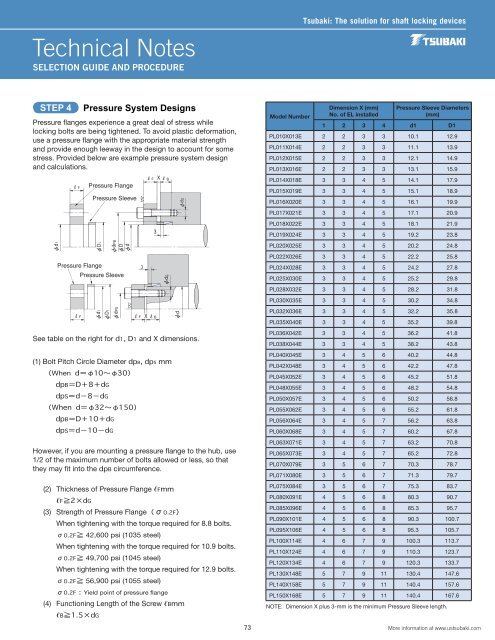
Technical NotesSELECTION GUIDE AND PROCEDURE<strong>Tsubaki</strong>: The solution for shaft locking devicesSTEP 4Pressure flanges experience a great deal of stress whilelocking bolts are being tightened. To avoid plastic deformation,use a pressure flange with the appropriate material strengthand provide enough leeway in the design to account for somestress. Provided below are example pressure system designand calculations.See table on the right for d1, D1 and X dimensions.(1) Bolt Pitch Circle Diameter dpB, dpS mm(When d=φ10〜φ30)dpB=D+8+dGdpS=d−8−dG(When d=φ32〜φ150)dpB=D+10+dGdpS=d−10−dGHowever, if you are mounting a pressure flange to the hub, use1/2 of the maximum number of bolts allowed or less, so thatthey may fit into the dpB circumference.(2) Thickness of Pressure Flange