U.S. TSUBAKI POWER-LOCK ®Technical NotesINSTALLATION AND REMOVALAS, AD, ADN, AE, FL, KE, TF, EF <strong>Series</strong> Installation and RemovalA. Installation(1) Verify that the shaft and the inner surface of the hub areclean, we recommend to lightly oil surfaces.Note: Do not use silicone or molybdenum lubricants.Otherwise, friction coefficient will reduce, andstandard torque will not be achieved.(2) Remove the bolts and clean all contact surfaces. Lightlycoat the bolts, including their bearing surfaces, with oilor grease. For AD/ADN <strong>Series</strong> POWER-LOCKs, use anoil bath or a spray method to thoroughly lubricate eachpart.(3) Tighten the bolts part way, and preliminarily assemblethe POWER-LOCK.Notes: 1. Pre-assemble by keeping the phases of theslit and the taps for removal out of synch. ForAD/ADN <strong>Series</strong>, maintain maximum spacebetween the taper rings.2. In the case of step shaft installation for AE<strong>Series</strong>, make sure the space between the huband the steps is greater than 1 mm.(4) Mount hub to shaft, and lightly push the POWER-LOCKto the end of the hub. Take caution in carrying out thisprocess with the AD/ADN <strong>Series</strong> for their taper anglesare relatively small.When the hub does not smoothly slide onto the shaft,either loosen the bolts or lightly tap on the hub until it isfixed into place.Notes: 1. Do not hit the POWER-LOCK with a hammer.This will severely damage the product andpossibly lead to accidents.2. Included spacer must be used with aTF <strong>Series</strong> POWER-LOCK. Without the spacer,the unit will not transmit torque.(5) Determine the position of the hub along the shaftcircumference and length. Using a torque wrench,tighten one bolt to approximately quarter of the specifiedtorque MA, and then tighten the one diagonally across inthe same manner. Repeat for the other bolts.(6) Using the torque wrench, tighten the bolts to onehalfthe specified torque MA and repeat the tighteningprocedure in step (5).(7) Bring up to full tightening torque MA and tighten as instep (5).(8) Tighten each bolt to full torque MA in a circular order.Repeat a few times until the bolts are completelytightened.Notes: 1. A torque wrench must be used to tighten thelocking bolts. Be sure to follow the aboveinstructions to tighten the bolts tothe specified torque. Hand-tightening ortightening with a wrench other than a torquewrench will result in incomplete installation,and lead to accidents.2. Exceeding the specified tightening torqueMA will damage the bolts. On the other hand,tightening to torque below MA will cause thebolts to loosen during operation. Be sure touse the correct torque to tighten these bolts.3. Do not use bolts other than those provided.Otherwise, bolts may damage and causeaccidents. If you misplace or damage anybolts, contact U.S. <strong>Tsubaki</strong> for replacement.B. Removal(1) Verify that no torque or thrust is applied to the hub andshaft.Note that in cases where a heavy shaft, hub or chain isused, disassembly may be slightly complicated. Afterremoving the load, disassemble the unit by looseningthe bolts in the correct order described in Installation A.Caution: Loosening the bolts will release the lockingfunction, which may cause the shaft to spin orjump out.(2) If the unit does not remove even after loosening all thebolts, tighten the bolts into the screw holes prepared forremoval. This will release the lock.Note: Take caution in installing and removing AD/ADN<strong>Series</strong> POWER-LOCKs for they have relativelysmaller taper angles.AS <strong>Series</strong>AE <strong>Series</strong>TF <strong>Series</strong>Parts1: Taper Ring A2: Taper Ring B3: Outer Ring4: Inner Ring5: <strong>Lock</strong>ing BoltsParts1: Outer Ring2: Inner Ring3: <strong>Lock</strong>ing BoltsParts1: Inner Ring2: Outer Ring3: Spacer4: <strong>Lock</strong>ing BoltsMore information at www.ustsubaki.com74
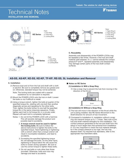
Technical NotesINSTALLATION AND REMOVAL<strong>Tsubaki</strong>: The solution for shaft locking devicesKE <strong>Series</strong>Parts1: Inner Ring2: Outer Ring3: <strong>Lock</strong>ing BoltsAD <strong>Series</strong>Parts1: Taper Ring A2: Taper Ring B3: Outer Ring4. Inner Ring5. <strong>Lock</strong>ing BoltsEF <strong>Series</strong>Parts1: Inner Ring2: Outer Ring3: <strong>Lock</strong>ing BoltsC. ReusabilityAssembly and disassembly of the POWER-LOCKs maybe repeated a few times. However, if the hub and shaftmaterial yield stresses σ0.2 cannot tolerate the contactpressure P and P', repeated assembly and disassemblymay damage certain parts of the hub-shaft contactsurfaces.AS-SS, AS-KP, KE-SS, KE-KP, TF-KP, RE-SS, SL Installation and RemovalA. Installation(1) Remove dust and oil from the hub and shaft with a clothor alcohol. Be sure to completely remove any grease andoil. Otherwise, standard torque may not be achieved.Note: The locking bolts are coated with a specialsubstance so no lubrication is required.(2) Mount the POWER-LOCK onto the hub or shaft. Loosenthe bolts or nut if difficult to install.(3) Using a torque wrench, tighten the bolts at quarter of thespecified torque MA, starting with one bolt then anotherdiagonally across and repeating for the other bolts.Then, tighten the bolts further to one-half the specifiedtorque MA in the same crisscross sequence. Finally,tighten each bolt to full torque MA in a circular order.Repeat until each bolt is completely tightened.Notes: 1. Do not hit the POWER-LOCK with a hammer.This will severely damage the product andpossibly lead to accidents.2. A torque wrench must be used to tightenthe locking bolts. Be sure to follow theabove instructions to tighten the bolts to thespecified torque. Hand-tightening or tighteningwith a wrench other than a torque wrench willresult in incomplete installation, and lead toaccidents.3. Exceeding the specified tightening torqueMA will damage the bolts. On the other hand,tightening to torque below MA will cause thebolts to loosen during operation. Be sure touse the correct torque to tighten these bolts.4. Do not use bolts or nuts other than thoseprovided. Otherwise, bolts and nuts maydamage and lead to accidents.■ Notes on RE <strong>Series</strong>(1) Installation A: With a Snap Ring1Use a snap ring to prevent the hub from moving in thedirection of the thrust.(2) Installation B: Without a Snap Ring1The hub will move in the direction of the thrust while theunit is being installed. See RE <strong>Series</strong> Movement in theShaft Direction for amount of hub movement.2Compared to Installation A, installation without a snapring can transmit torque up to 1.7 times. Take note of thehub and shaft material strengths for this installation. Thecontact pressure generated at the hub and shaft from thissetup is much larger than that achieved from InstallationA. It is very important to check the hub material strength,for if the contact pressure is too high, the hub maydisplace itself. For required hub diameters, refer to theappropriate Hub Diameters table.75More information at www.ustsubaki.com