XT-Micro manual, Version 1.0 - AK-Nord GmbH
XT-Micro manual, Version 1.0 - AK-Nord GmbH
XT-Micro manual, Version 1.0 - AK-Nord GmbH
- No tags were found...

You also want an ePaper? Increase the reach of your titles
YUMPU automatically turns print PDFs into web optimized ePapers that Google loves.
<strong>XT</strong>-MICRO<strong>XT</strong>- MICROTechnical dataCentronics 36Pin RS232 25Pin Sub-D Jack RS232 25Pin Sub-D PlugDimensions:Power supply:45 x 48x 14 (mm)5Volt / about 300 mANetwork Connection:Network speed:Network Protocol:<strong>XT</strong>-MICRO-CEthernet 10/100MBit RJ4510/100 Mbit Full/Half DuplexIP, TCP,UDP, FTP,ICMP, DHCP, DNS, DDNS, ARP, BOOTP,HTML, HTTP, TELNET, SNMP, DYNDNSLPR,IPPSerial Connection:Serial Protocol:Special features:V1 - 25 Pin Sub-D Jack, V2 - 25 Pin Sub-D Plug300-115200 Baud, 7-8Bit, Odd-Even paritySignals: TXD, RXD, RTS, CTS, DSR, DTR, DCD,GNDModem – Emulation, PAD – Emulation, ConnectOnData,DYNDNS,UDP-KEEP-ALIVECentronics Connection:Centronics Features:36 Pol Centronics PlugBidirectional, IEEE1284<strong>XT</strong>-<strong>Micro</strong> <strong>manual</strong>, <strong>Version</strong> <strong>1.0</strong>3
Hardware - description <strong>XT</strong>-MICRO V2<strong>XT</strong>-MICRO25 PIN SUB-DPlugTXD(2) RXD(3) RTS(4) CTS(5) DSR(6) GND(7) DCD(8)DTR(20)<strong>XT</strong>-<strong>Micro</strong> <strong>manual</strong>, <strong>Version</strong> <strong>1.0</strong>5
<strong>XT</strong>-MICRO<strong>XT</strong>-MICRO LED description:Network activityNetwork linkstatus LEDFlashes in aseconds clockpulse<strong>XT</strong>-<strong>Micro</strong> <strong>manual</strong>, <strong>Version</strong> <strong>1.0</strong>6
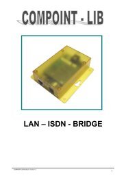
ConLine<strong>AK</strong>-ConLine-V24Techical dataPower supply:5 V 500mA100Mbit. 300 mA10Mbit 180 mANetwork Connection:Network speed:Network Protocol:RJ4510/100 MBit Full/Half Duplex,AutoIP, TCP,UDP, FTP,ICMP, DHCP, DNS, DDNS, ARP, BOOTP,HTML, HTTP, TELNET, SNMP, DYNDNSSerial Connection:Serial Protocol:9Pin Sub-D jack or plug300-115200 Baud, 7-8Bit, Odd, Even, Mark, Space, None ParitySignals: TXD, RXD, RTS, CTS, DSR, DTR, DCD, GNDSpecial features:Modem – Emulation, PAD – Emulation, ConnectOnData,DYNDNS,UDP-KEEP-ALIVE<strong>XT</strong>-<strong>Micro</strong> <strong>manual</strong>, <strong>Version</strong> <strong>1.0</strong>7
ConLine<strong>AK</strong>-ConLine-V24: Hardware - description RS232 – V24 – Interface9 PIN SUB-DPLUGDCD(1) RXD(2) TXD(3) DTR(4) GND(5)DSR(6) RTS(7) CTS(8)9 PIN SUB-DJACKDCD(1) TXD(2) RXD(3) DSR(4) GND(5)DTR(6) CTS(7) RTS(8)<strong>XT</strong>-<strong>Micro</strong> <strong>manual</strong>, <strong>Version</strong> <strong>1.0</strong>8
ConLine<strong>AK</strong>-ConLine-V24: Hardware - description InterfaceNetwork LED POWER1 21: Network link2: Network activity<strong>XT</strong>-<strong>Micro</strong> <strong>manual</strong>, <strong>Version</strong> <strong>1.0</strong>9
ConLine<strong>AK</strong>-ConLine-USBTechical dataPower supply:5 V 500mA100Mbit. 300 mA10Mbit 180 mANetwork Connection:Network speed:Network Protocol:RJ4510/100 MBit Full/Half Duplex,AutoIP, TCP,UDP, ICMP, DHCP, DNS, DDNS, ARP, BOOTP, HTML,HTTP, TELNET, SNMP,LPR,IPPUSB Connection:USB Protocol:USB-B PlugPrinter USB1.1 und USB 2.0 compatible and IEEE1284-4<strong>XT</strong>-<strong>Micro</strong> <strong>manual</strong>, <strong>Version</strong> <strong>1.0</strong>10
ConLine<strong>AK</strong>-ConLine-USB: Hardware - description InterfaceNetwork LED POWER1 21: Network link2: Network activity<strong>XT</strong>-<strong>Micro</strong> <strong>manual</strong>, <strong>Version</strong> <strong>1.0</strong>11
InterfacePort descriptionPortInterface<strong>XT</strong>-MICRO IOC V EMC<strong>XT</strong>-MICRO IIComPoint –LAN IComPoint-LAN IIConLineO SV E O S AS S AS USBM CV24COM1 der Schnittstelle515(LPR) X X X X X X X X X1002 X X X X X X X X X X X X X3000 X X X X X X X X X X X X X6500 X X X X X X X X X X X X X6563 X X X X X X X X X6564 X X X X X X X X X8000 X X X X X X X X X X X X X8888 X X X X X X X X X X X X X9084 X X X X X X X X X X X X X9100 X X X X X X X X X X X X X10001 X X X X X X X X X X X X X11111 X X X X X X X X X X X X XCOM2 der Schnittstelle1003 X X3001 X X6501 X X6565 X X6566 X X8001 X X8888 X X9085 X X9101 X X10002 X X22222 X X<strong>XT</strong>-MINICVOEM<strong>XT</strong>-<strong>Micro</strong> <strong>manual</strong>, <strong>Version</strong> <strong>1.0</strong>12
InterfacePort DescriptionDescription special ports:6563/6565: About this port the COM will open with a baud rate of 96006564/6566: About this port the COM will open with a baud rate of 1152008000/8001: A Connection on this port will avoid the port timeout. This port will not bedisconnected by the port timeout.8888: Reset port for port 8000/8001.Disconnects all TCP/IP connections on COM1and COM2.9084: Reset port for port 8000. Disconnects all TCP/IP connections on COM1.9085: Reset port for port 8001. Disconnects all TCP/IP connections on COM2.11111: About this port it’s possibly to control all Signals,Baudrats,Databits and theflow control of the COM1. For this port there is a additional description. Youcan employ this port in the program "VirtualCom". All qualities aretransmitted then to the interface22222: About this port it’s possibly to control all Signals,Baudrats,Databits and theflow control of the COM2. For this port there is a additional description. Youcan employ this port in the program "VirtualCom". All qualities aretransmitted then to the interface<strong>XT</strong>-<strong>Micro</strong> <strong>manual</strong>, <strong>Version</strong> <strong>1.0</strong>13
TCP/IP NetworkExample of a TCP / IP network with <strong>XT</strong>-MICRO.administrationworkstation 1IP-No = 149.213.015.002expeditionworkstation 1IP-No = 149.213.016.002administrationworkstation 2IP-No = 149.213.015.003Server No1IP-No = 149.213.015.001Server No2IP-No = 149.213.016.001expeditionworkstation 2IP-No = 149.213.016.003<strong>AK</strong>-<strong>XT</strong>-MICROIP-No=149.213.016.004administratorworkstation 3IP-No = 149.213.015.004Router 1HAMBURGadministratorworkstation 4IP-No = 149.213.015.005Cenronics Interface10/100Mbit Fast EthernetRouter 2MÜNCHEN<strong>AK</strong>-<strong>XT</strong>-MICROIP-No=149.213.015.006productionworkstation 1IP-No = 149.213.017.00210/100Mbit Fast EthernetSerial Interfaceproductionworkstation 2IP-No = 149.213.017.003productionworkstation 3IP-No = 149.213.017.004Server Nr3IP-No = 149.213.017.001<strong>XT</strong>-<strong>Micro</strong> <strong>manual</strong>, <strong>Version</strong> <strong>1.0</strong>14
Function of <strong>XT</strong>-MICRO in the TCP/IP netTCP/IP NetworkA TCP/IP network is composed by one or more server and the workstations connected bya LAN cable. Each subscriber in a TCP/IP network has a unique IP-number and can thusbe clearly identified. These IP-numbers consist of 4 figures between 0 and 255 (octet),separated by a dot:Examples: 149.213.48.93 or 109.89.1.3 or 56.3.58.134 different types of addresses are distinguished:1. Addresses of type AIn the addresses of type A, the first octet assigns the network address (0 to127) and thethree following octets assign the address of the PC. The subscribers of such a networkonly have the first figures of their IP-address in common, all other figures are different (i.e.121.213.13.22, 121.122.30.89 , 121.23.111.1, etc.). This kind of addressing is only used invery large networks, as it allows a quantity of 256 to 3 addresses.2. Addresses of type BThe addresses of type B assign the first two octets and the designations of the PCs aredistinguished by the last two octets. Some IP numbers of a type B network are: 139.<strong>1.0</strong>.1,139.1.234.89, 139.1.45.9, etc.. The maximum number of subscribers is determinate by256 to 2 and the first figure of the IP number is usually between 128 and 191.3. Addresses of type CThe addresses of type C assign the network address in the first 3 octets and thedesignation of the PC in the fourth octet. Please find following some examples of a type Cnetwork: 101.83.12.03, 101.83.12.243, 101.83.12.120 . The maximum number ofsubscribers is limited to 256 and thus many networks with a few PCs can be addressed.The usual range of values for the first figures of the IP number is between 192 and 223.4. Addresses of type DFor addresses of type D the four bits of highest value in the IP number are = 1110 andthus results the range of values between 224 and 239 for the first figure of the IP number.This kind of addressing is called Multicast and is applied for new IP protocols.In a TCP/IP network, <strong>XT</strong>-MICRO must get a clear IP number according to abovementioned types. <strong>XT</strong>-MICRO has no passive part in a TCP/IP network in contrast toNOVELL networks and is addressed by other subscribers by means of the IP address anddoes not activate a connection independently.<strong>XT</strong>-<strong>Micro</strong> <strong>manual</strong>, <strong>Version</strong> <strong>1.0</strong>15
Function of <strong>XT</strong>-MICRO in the TCP/IP netTCP/IP NetworkIn the example given on the previous page, a network of three servers and three class Caddresses is shown. The administration works in a 16/4 M/Bits token ring network with 4workstations on server No 1 with the IP addresses 149.213.15.xxx, the expedition with 2workstations in a 10 M/Bits Ethernet network on server No 2 with the IP addresses149.213.16.xxx and the production with 3 workstations on server No 3 with the IPaddresses 149.213.17.xxx. The communication from the administration to the expeditionis via a fixed LAN cabling, to the production department via a router with a telecomconnection. The printer of the administration is connected by XRAFFIC over a serialinterface and the printer of the expedition department by <strong>XT</strong>RAFFIC over the Centronicsinterface. Each PC of the administration can set up a communication to <strong>XT</strong>RAFFIC andcan transmit printing data via spooler system, FTP or other.For the communication of two subscribers of a TCP/IP net over different types, it isessential which subnet mask was defined. Each subscriber to the network assigns with thehelp of this mask which other IP subscribers can be addressed. Therefore the targetaddress is linked by an AND function to the subnet mask and the result is compared to theextended target address. A figure of 255 in the subnet mask means that an indication ofthe address is not interpreted at this stage and the figure 0 means that an analysis ismade.Please find following some examples:proper address 123.49.89.13subnet mask 255.255.0.0You can dial up the addresses 123.49.xxx.xxx, i.e. 123.49.200.10 or 123.49.30.3, etc.but not 123.50.200.10proper address 123.49.89.13subnet mask 255.255.255.0You can dial up the addresses 123.49.89.xxx, i.e. 123.49.89.10 or 123.49.89.3, etc.but not 123.49.200.10In the example already described, in order to establish a communication betweenworkstation 3 of the administration and <strong>XT</strong>RAFFIC, the subnet mask of workstation 3 aswell as of the LAN connection from server No 1 to server No 2 must be switched to.For LAN communications via router, a link via subnet mask must be released and therouting must be configured with a default gateway entry on the corresponding router.<strong>XT</strong>-<strong>Micro</strong> <strong>manual</strong>, <strong>Version</strong> <strong>1.0</strong>16
Setting of the IP address with DHCP.TCP/IP Network1.) <strong>XT</strong>RAFFIC is operational and connected to a printer2.) For network interface on <strong>XT</strong>RAFFIC, DHCP must be turned on(standard configuration)3.) DHCP must be available in the LAN segment4.) Turn <strong>XT</strong>RAFFIC on5.) Output of status printout and control of IP addressFunction:<strong>XT</strong>RAFFIC includes all mechanisms of the DHCP (Dynamic Host Configure protocol) andtherefore a DHCP server can assign an IP address. The IP address can be assignedfirmly (static assignment) or can vary within a range of IP addresses, according to theconfiguration of the DHCP server. Other features of the DHCP such as Lease Time, etc.are fully supported by <strong>XT</strong>RAFFIC.Please find following a typical entry on a Windows NT DHCP server:<strong>XT</strong>-<strong>Micro</strong> <strong>manual</strong>, <strong>Version</strong> <strong>1.0</strong>17
Setting of the IP address with DHCP.TCP/IP NetworkSetting an address range from 149.213.100.100 to 149.213.100.200<strong>XT</strong>-<strong>Micro</strong> <strong>manual</strong>, <strong>Version</strong> <strong>1.0</strong>18
TestpageHow to print a Testpage:Connect the <strong>XT</strong>-MICRO to the printer but leave the network cable away. Now turn on thePrinter and the <strong>XT</strong>-MICRO. After 10 sec. The Testpage will be printed. Now you canconnectthe <strong>XT</strong>-MICRO to your network.Attention = NO LINK ON LAN============================== Ethernet Menu ============================MAC – Address= 08-BB-CC-00-90-00IP –Address = 192.168.123.123SubnetMask = 255.255.255.0Name of Interface= <strong>XT</strong>-00-90-00-C2DHCP Y/N= YBOOT/P Y/N= NPort Timeout = 30Standard Gateway = 0.0.0.0Secondary Gateway = 0.0.0.0DHCP Server = 0.0.0.0DNS Server1 = 0.0.0.0DNS Server2 = 0.0.0.0DNS Domain =Ethernet Speed= AUTOIN USEGateway1,Gateway2 = 0.0.0.0 , 0.0.0.0DHCP Server = 0.0.0.0DNS Server1,Server2 = 0.0.0.0 , 0.0.0.0DNS Domain =============================== LPT MENU =================================Interface Mode = 0Bidirect Y/N/A= YPrint Page Y/N/A= AEmulation= NONEEmuCode = 0000MANUFACTURER =COMMAND SET =MODEL =DESCRIPTION =DISPLAY= HW ONLINE============================== INFO MENU ================================Software Low = 7B3D Date = 29.8.2004Software High = 7B3D Date = 29.8.2004Lan Driver / State = 2 / 4000EEP Driver = 1Hardware <strong>Version</strong>= D0DISPLAY= HW ONLINESTATE= ReadySocket 0= CLOSEDHis IP/PORT = \My IP/PORT = \Socket 1= CLOSEDHis IP/PORT = \My IP/PORT = \Socket 2= CLOSEDHis IP/PORT = \My IP/PORT = \Socket 3= CLOSEDHis IP/PORT = \My IP/PORT = \<strong>XT</strong>-<strong>Micro</strong> <strong>manual</strong>, <strong>Version</strong> <strong>1.0</strong>19
TELNETConfiguration of <strong>XT</strong>-MICRO1.) <strong>XT</strong>-MINI is operational.2.) The IP address is set (and/or known). see “Adjustment of IP address”3.) <strong>XT</strong>RAFFIC is not occupied4.) Program “TELNET” is available.Example:The configuration of the <strong>XT</strong>-Mini is supposed to be checked.1Start the program Telnet. You will find it either on the PC in the directory“WINDOWS” or it will be at your disposal on a system ( OS/2 , Linux ) byentering "TELNET" + < ENTER>. You can then establish a communicationto <strong>XT</strong>-Mini by entering the IP address.WillkommenDas Escapezeichen ist 'CTRL++'Minisoft Telnet> open 100.100.66.2<strong>XT</strong>-<strong>Micro</strong> <strong>manual</strong>, <strong>Version</strong> <strong>1.0</strong>20
TELNETConfiguration of <strong>XT</strong>-MICRO2Enter the standard password „<strong>XT</strong>“ in the Password menu.PASSWORD MENU-----------------------------------------------------------------------------[Q = QUIT] Password:3Press enter. You are now in the Main Menu of the <strong>XT</strong>-Mini. Here you canchoose the Interface you like to configure.=========================== MAIN MENU =======================================1 = ETHERNET MENU2 = LPT MENU3 = INFO MENU4 = ADMIN MENU5 = DUMP LPTQ = EXIT TELNET(reset if any value changed)-----------------------------------------------------------------------------[Q = QUIT] Please enter your choice:<strong>XT</strong>-<strong>Micro</strong> <strong>manual</strong>, <strong>Version</strong> <strong>1.0</strong>21
TELNETConfiguration of <strong>XT</strong>-<strong>Micro</strong> serial4Menu 1, the „Ethernet Menu“1 = MAC - Address = 08-BB-CC-04-5F-552 = IP - Address = 100.100.100.1563 = SubnetMask = 255.255.255.04 = Name of Interface = <strong>XT</strong>-MICRO-045F555 = DHCP Y/N = Y6 = BOOT/P Y/N = N7 = Port Timeout = 108 = Standard Gateway = 0.0.0.0 ,used:100.100.100.19 = Secondary Gateway = 0.0.0.0 ,used:0.0.0.0a = DHCP Server= 0.0.0.0 ,used:100.100.100.1b = DNS Server1= 0.0.0.0 ,used:100.100.100.1c = DNS Server2= 0.0.0.0 ,used:0.0.0.0d = DNS Domain= TESTe = Ethernet Speed = AUTOf = Without nagle mode = Ng = Repeat packet time = 1For example:'2=100.99.88.7'-----------------------------------------------------------------------------[Q = QUIT] Please enter your choice:1=Mac – Address :2=IP – Address :3=SubnetMask:4=Name of interface:5=DHCP Y/N:6=Boot/P Y/N:7=Porttimeout :8=Standard Gateway :You can change the MAC-address here. We recommend you to use the standard MACaddress.Change the IP-address of the interface at this pointexample: 2=192.168.0.1change the Subnet-Mask at this pointexample: 3=255.255.255.0If your network uses DNS name server you can enter a name for the Interface at this pointexample: 4=<strong>XT</strong>-<strong>Micro</strong>If you use an DHCP Server this point must be set to Y (Yes)example: 5=YIf you use an BOOT/P Server this point must be set to Y (Yes)example: 6=YAfter x seconds of inactivity, the port time out will drop down the connection.example: 7=25Porttiemout = 0 = Disable Porttimeout.If you use a gateway in your network you should enter it at this point.example: 8=192.168.0.259=Secondary Gateway : If you use a secondary gateway in your network you should enter it at this point.example: 9=192.168.0.26A=DHCP Server :If you know the IP-address of the DHCP server you should enter the IP at this pointexample: a=192.168.0.35NOTE: “used “ shows current values of the parameters<strong>XT</strong>-<strong>Micro</strong> <strong>manual</strong>, <strong>Version</strong> <strong>1.0</strong>22
TELNETConfiguration of <strong>XT</strong>-<strong>Micro</strong> serial4Menu 1, the „Ethernet Menu“1 = MAC - Address = 08-BB-CC-04-5F-552 = IP - Address = 100.100.100.1563 = SubnetMask = 255.255.255.04 = Name of Interface = <strong>XT</strong>-MICRO-045F555 = DHCP Y/N = Y6 = BOOT/P Y/N = N7 = Port Timeout = 108 = Standard Gateway = 0.0.0.0 ,used:100.100.100.19 = Secondary Gateway = 0.0.0.0 ,used:0.0.0.0a = DHCP Server= 0.0.0.0 ,used:100.100.100.1b = DNS Server1= 0.0.0.0 ,used:100.100.100.1c = DNS Server2= 0.0.0.0 ,used:0.0.0.0d = DNS Domain= TESTe = Ethernet Speed = AUTOf = Without nagle mode = Ng = Repeat packet time = 1For example:'2=100.99.88.7'-----------------------------------------------------------------------------[Q = QUIT] Please enter your choice:B=DNS Server1 :C=DNS Server2 :D=DNS Domain :E=Ethernet Speed :Enter the IP-address of the DNS server here.example: b=192.168.0.66Enter the IP-address of a secondary DNS server here.example: c=192.168.0.67If you use your interface in a domain, you can enter the domain-name here.example: d=exampledomain.deYou can set up your Ethernet Speed hereThe following modes are available:e=10HALF 10Mbit Half/duplexe=10FULL 10Mbit Full/duplexe=100HALF 100Mbit Half/duplexe=100FULL 100Mbit Full/duplexe=AUTO AUTO sensingF=Without nagle mode: If you set this parameter to “Y”, then we generate no additional TCP-ACK packet after thedata packet (TCP-PSH). It provides, however, that the connection partner possibly 200 mswaits, until he passes the data packet to the application.G=Repeat packet timeThis value is adjustable from 1-10 seconds. It repeats after this time the last data packet,when this not was acknowledged.To exit the menu, press „q“ for quit. All parameters will be saved automatically.<strong>XT</strong>-<strong>Micro</strong> <strong>manual</strong>, <strong>Version</strong> <strong>1.0</strong>23
TELNETConfiguration of <strong>XT</strong>-MICRO C (only centronics <strong>Version</strong>)5 ===========================Menu 2, the „LPT Menu“LPT MENU ========================================1 = Interface Mode = 02 = Bidirectional Y/N = Y3 = Print Page Y/N/A = A4 = Emulation = NONE5 = EmuCode = 0000MANUFACTURER =COMMAND SET =MODEL =DESCRIPTION =DISPLAY= HW PAPER EMPTYInterface Lines =+-----------------------------------------------------------+|Name |STR |ACK |BUSY |PE |SEL |ATFD |ERR |INIT |SELIN||Def. |HIGH |HIGH |LOW |LOW |HIGH |HIGH |HIGH |HIGH |LOW ||Value|HIGH |HIGH |HIGH |HIGH |LOW |HIGH |HIGH |HIGH |LOW |+-----------------------------------------------------------+For example:'1=0'-----------------------------------------------------------------------------[Q = QUIT] Please enter your choice:1=interface Mode :2=Bidirectional Y/N/A :3=Print Page Y/N/A :4=Emulation :5=EmuCode :0=Auto IEEE12841=SPP IEEE1284 Nibble Mode2=SPP IEEE1284 Byte Mode3=ECP IEEE1284example: 1=0BidirectionalY=activeN=disabledA=calls the printer.example: 2=YY= testpage will be printed every start, N= no testpage will be printed, A= Testpage will beprinted when no Network cable is connected after system start.example: 3=Acustomer specific emulationscustomer specific settingsIn the lower menu you can see the current status of the printer<strong>XT</strong>-<strong>Micro</strong> <strong>manual</strong>, <strong>Version</strong> <strong>1.0</strong>24
TELNETConfiguration of ConLine-USB (only USB version)6 ===========================„USB Menu“USB MENU ========================================1 = Bidirect Y/N = A2 = Emulation = NONE3 = EmuCode = 0000USB Class= 7 = PRINTERUSB SubClass = 1USB Protocol = 3USB VendorID = 03F0USB ProductID = 1D17USB Manufacturer = Hewlett-PackardUSB Productname = hp LaserJet 1320 seriesUSB SN= 00CNHW5D0GYCPRINTER Manufacturer= Hewlett-PackardPRINTER Command set = PJL,MLC,BIDI-ECP,PCL,POSTSCRIPT,PCLXLPRINTER Model = hp LaserJet 1320 seriesPRINTER Description = Hewlett-Packard LaserJet 1320 seriesDISPLAY= 38 ReadyFor example:'1=N'-----------------------------------------------------------------------------[Q = QUIT] Please enter your choice:1=Bidirect Y/N :N = NO.Diables the bidirektional.Y = YESIn this case all PJL – Information returned to the system.A = Automatisch.In this case all PJL – Information returned to the system and in offline mode theInterface read the Display message from the Printer.2=Emulation :3=Emu-Code:No functioncustomer specific settingsUSB – Protokoll 1 und 2In This Case, the port status is read and processed The port status shows informationas PaperEmpty, Error aso. With the EMU code 0001 this function can be switched offand the printer is always online.EMU-Code 0002The automatic protocol recognition is switched off and the pint server prints only withthe USB - protocol 1.EMU-Code 0004The automatic protocol recognition is switched off and the pint server prints only withthe USB - protocol 3. IEEE1284.4All other values are used only for the information.TIP:The USB – Class must have the value „7“ = Printer.<strong>XT</strong>-<strong>Micro</strong> <strong>manual</strong>, <strong>Version</strong> <strong>1.0</strong>25
TELNETConfiguration of <strong>XT</strong>-MICRO V (only serial version)7 ===========================Menu 2, the „interface Menu“COM1 MENU =======================================1 = Destination IP1 = 0.0.0.02 = Destination PORT1 = 03 = Destination DNS1 =4 = Destination IP2 = 0.0.0.05 = Destination PORT2 = 06 = Destination DNS2 =7 = Connection Setuptime= 208 = Connection Time/Dst = 59 = InputTimeOut *10ms = 10a = Baudrate:9600 b = Databits:8 c = Parity:N d = Stopbits:1e = Flow Control:N f = Emulation:NONE g = EmuCode:0000h = RTS:0 i = DCD:1 j = DTR:1 k = DSR:2Interface Lines =+-----------------------------------+|Name |RTS |CTS |DTR |DSR |DCD ||Def. |LOW |LOW |LOW |LOW |HIGH ||Value|LOW |HIGH |HIGH |HIGH |HIGH |+-----------------------------------+For example:'1=192.168.10.2'-----------------------------------------------------------------------------[Q = QUIT] Please enter your choice:1=Destination IP1 : If you use the ConnectOnData mode, the data will be sent to this IP-addressexample: 1=192.168.0.22=Destination Port1 : Enter the target port of the Host hereexample: 2=80803=DNS1 :If you use DNS, you can also enter the DNS name of the target host.example: 3=destinationhost1.example.de4=Destination IP2 : If the first target address is not available, the interface will try the second target address.example: 4=192.168.0.35=Destination Port2 : Enter the target port of the second address here.example: 5=80806=DNS2 :The DNS name of the second target can be set here.example: 6=destinationhost2.example.de7=Connection Setuptime:This parameter set up the time that the Interface should connect to the Host.example: 7=208=Connection Time/Dst: Determine how often the interface should connect to the target. If 2 addresses are set, theinterface will exchange the address after an unsuccessful connection.Example: 8=59=InputTimeOut *100ms :Determine how long the interface will wait, until serial data will be send to the network.Example: 9=3 (Timeout auf 300ms)A=Baudrate:Set up the baudrate of your interface. Following modes are able:2400, 4800, 9600, 19200, 38400, 57600example: a=9600B=Databits:Set up the databits here:7, 8example: b=8C=Parity:ODD = O , EVEN = Eexample:c=ED=Stopbits: Number of stopbits, 1,2example: d=1E=FlowControl Turn flow control on or off. S=Software(XON/XOFF) H=Hardware(RTS/CTS) N=NONEexample:e=H<strong>XT</strong>-<strong>Micro</strong> <strong>manual</strong>, <strong>Version</strong> <strong>1.0</strong>26
TELNETConfiguration of <strong>XT</strong>-MICRO V (only serial version)8===========================Continuation menu 2, the " interface Menu "COM1 MENU =======================================1 = Destination IP1 = 0.0.0.02 = Destination PORT1 = 03 = Destination DNS1 =4 = Destination IP2 = 0.0.0.05 = Destination PORT2 = 06 = Destination DNS2 =7 = Connection Setuptime= 208 = Connection Time/Dst = 59 = InputTimeOut *10ms = 10a = Baudrate:9600 b = Databits:8 c = Parity:N d = Stopbits:1e = Flow Control:N f = Emulation:NONE g = EmuCode:0000h = RTS:0 i = DCD:1 j = DTR:1 k = DSR:2Interface Lines =+-----------------------------------+|Name |RTS |CTS |DTR |DSR |DCD ||Def. |LOW |LOW |LOW |LOW |HIGH ||Value|LOW |HIGH |HIGH |HIGH |HIGH |+-----------------------------------+For example:'1=192.168.10.2'-----------------------------------------------------------------------------[Q = QUIT] Please enter your choice:F=Emulation:G=Emucode:H=RTS/CTS:I=DCD:J=DTR:K=DSR:The following emulations are available:Modem- Emulation example: f=MODEMPAD-Emulation example: f=PADConnectOnData example: f=DIRECTNo Emulation example: f=NOUnder this menu item you can release special functionThis menu item chooses the behavior of the RTS line (output)h=0 RTS Always ONh=1 RTS Follows CTSh=2 RTS Follows DSRh=3 RTS Always ON + Hardware Protocolh=4 RTS Follows CTS + Hardware Protocolh=5 RTS Follows DSR + Hardware ProtocolThis menu item chooses the behavior of the DCD line (output)i=0 DCD Always ONi=1 Indicates Connectioni=2 Follows DSRi=3 Set to inputThis menu item chooses the behavior of the DTR line (output)j=0 DTR Always ONj=1 Indicate Connectionj=2 Follows DSRThis menu item chooses the behavior of the DSR line (input)k=0 DSR No Controlk=1 DSR Control Incomingk=2 DSR Clear Connection<strong>XT</strong>-<strong>Micro</strong> <strong>manual</strong>, <strong>Version</strong> <strong>1.0</strong>27
TELNETConfiguration of <strong>XT</strong>-MICRO9 ===========================Menu 3, the „info menu“INFO MENU =======================================Software Checksum = 3CADSoftware Date = 7.7.2004Lan Driver / State = 4 / 0000EEP Driver = 3Hardware <strong>Version</strong> = 4Socket0= ESTABLISHEDHis IP/PORT = 192.168.23.101 / 1440My IP/PORT = 192.168.66.155 / 23Socket1= CLOSEDHis IP/PORT = /My IP/PORT = /Socket2= CLOSEDHis IP/PORT = /My IP/PORT = /Socket3= CLOSEDHis IP/PORT = /My IP/PORT = /-----------------------------------------------------------------------------[Q = QUIT] Please enter your choice:In the Info menu all versions of the interface will be displayed. There is as well the updatefunction. This function allows a firmware update. If you want to make a firmware updateuse 1=T (Temp) This means, that the function will return to N after the update. If youactivate Y, the firmware update will always work.10menu 4, the „admin menu“=========================== ADMINISTRATION MENU =============================1 = Download Y/N = N2 = Password =3 = Interface PORT = 10024 = Snmp Trap Y/N = N5 = Snmp Target IP = 255.255.255.2556 = Snmp Target PORT = 162-----------------------------------------------------------------------------[Q = QUIT] Please enter your choice:1=Download: allow software update Y=yes, N=no, T=temp (after update the state will turn to N)2=Password:enter your new password3=Interface Port: enter a custom port.4=SNMP Trap: activates or disable the SNMP traps.5=SNMP Target IP: if avalible, you can enter the IP of the SNMP server.6=SNMP Target Port: the port for the SNMP connection<strong>XT</strong>-<strong>Micro</strong> <strong>manual</strong>, <strong>Version</strong> <strong>1.0</strong>28
TELNETConfiguration of <strong>XT</strong>-MICRO11menu 5, the „dump menu“=========================== DUMP MENU =======================================00 00 00 00 00 00 00 00 00 00 00 00 00 00 00 00 ................00 00 00 00 00 00 00 00 00 00 00 00 00 00 00 00 ................00 00 00 00 00 00 00 00 00 00 00 00 00 00 00 00 ................00 00 00 00 00 00 00 00 00 00 00 00 00 00 00 00 ................00 00 00 00 00 00 00 00 00 00 00 00 00 00 00 00 ................00 00 00 00 00 00 00 00 00 00 00 00 00 00 00 00 ................00 00 00 00 00 00 00 00 00 00 00 00 00 00 00 00 ................00 00 00 00 00 00 00 00 00 00 00 00 00 00 00 00 ................00 00 00 00 00 00 00 00 00 00 00 00 00 00 00 00 ................00 00 00 00 00 00 00 00 00 00 00 00 00 00 00 00 ................00 00 00 00 00 00 00 00 00 00 00 00 00 00 00 00 ................00 00 00 00 00 00 00 00 00 00 00 00 00 00 00 00 ................00 00 00 00 00 00 00 00 00 00 00 00 00 00 00 00 ................00 00 00 00 00 00 00 00 00 00 00 00 00 00 00 00 ................00 00 00 00 00 00 00 00 00 00 00 00 00 00 00 00 ................00 00 00 00 00 00 00 00 00 00 00 00 00 00 00 00 ................c = Clear Bufferr = Refresh-----------------------------------------------------------------------------[Q = QUIT] Please enter your choice:In the dump menu the data of the serial interface will be displayed. You can check theserial interface for any problems, such as wrong baudrate, etc.To leave the telnet menu press „q“ to quit to the main menu. All modifiedparameters are being saved automatically.<strong>XT</strong>-<strong>Micro</strong> <strong>manual</strong>, <strong>Version</strong> <strong>1.0</strong>29
<strong>XT</strong>-AdminDescription <strong>XT</strong>-AdminOn the following pages the configuration and management tool <strong>XT</strong>-Admin will bedescribed3 4 4 4 4121. Any <strong>AK</strong>-<strong>Nord</strong> interface will be displayed on the network.2. The interfaces are expanded by a click onto the cross. If no cross should beavailable, you can’t reach the interface.3. The interfaces on the list will be refreshed by pushing the „Refresh“ button.4. These functions are not supported by the <strong>XT</strong>-MICRO.<strong>XT</strong>-<strong>Micro</strong> <strong>manual</strong>, <strong>Version</strong> <strong>1.0</strong>30
<strong>XT</strong>-AdminDescription <strong>XT</strong>-Admin, SCANIf you want to display an <strong>XT</strong>-MICRO which is located outside of your subnet or which isinstalled behind a Gateway, it is not being displayed automatically. But you have theoption to scan a certain IP-area and to have the interface listed in this way.14321. If you press the „SCAN“ button the <strong>XT</strong>SCAN window will appear.2. Enter the IP-range which you want to scan.3. Choose the speed for the scan. In fast networks (like Ethernet) use the „Scan fast“button, in slow networks use the „Scan slow“ button.4. When all parameters are set, press the „SCAN“ button in order to start theprocedure. Every interface which is being detected, will appear in the list on the left.<strong>XT</strong>-<strong>Micro</strong> <strong>manual</strong>, <strong>Version</strong> <strong>1.0</strong>31
<strong>XT</strong>-AdminDescription <strong>XT</strong>-Admin, Set IPBy the Set IP function you can set new IP-addresses to your interfaces, just by pressing abutton, even if these interfaces are outside of your subnet.124192 168 0 1031. If you press the „Set IP“ button, the <strong>XT</strong>IP window will appear.2. Choose the interface from the left menu which you will change the IP-address. Witha click to that interface, the parameters will be transmitted to the <strong>XT</strong>IP Window.3. Enter the new IP-address in this Window.4. To set the new IP-address press the „Set IP“ Button in the <strong>XT</strong>IP Window. Afterpressing the button, the interface will appear in the left window together with its newIP-address.<strong>XT</strong>-<strong>Micro</strong> <strong>manual</strong>, <strong>Version</strong> <strong>1.0</strong>32
<strong>XT</strong>-AdminDescription <strong>XT</strong>-Admin, TelnetBy the function Telnet, you can use a Telnet window to connect to your interfaces.1321. If you press the „Telnet“ button, the Telnet window will appear.2. Choose the interface which you want to configure from the menu on the left. NOTE:the cross in front of the interface must be visible to connect to the Interface.Otherwise check your network parameters.3. Press „Connect“ to connect to the interface. For detailed information on theconfiguration of the <strong>XT</strong>-MICRO please refer to the Telnet chapter.<strong>XT</strong>-<strong>Micro</strong> <strong>manual</strong>, <strong>Version</strong> <strong>1.0</strong>33
<strong>XT</strong>-AdminDescription <strong>XT</strong>-Admin, UpdateWith the Update function you can load new Firmware in your interfaces over the Ethernet.14231. If you press the „Update“ button, the Update window will appear.2. Choose the type of the interface which you want to update.3. Choose the Interface which you want to update. NOTE: the cross in front of theinterface must be visible to connect to the Interface. Otherwise check your networkparameters. You can choose more than one interface. The interfaces will be listedand updated one by one.4. When all interfaces are listed press the Update button to start the automaticupdate. When the update is terminated, the new version and date will be displayedin the list.<strong>XT</strong>-<strong>Micro</strong> <strong>manual</strong>, <strong>Version</strong> <strong>1.0</strong>34
Description <strong>XT</strong>-Admin, File Transfer<strong>XT</strong>-AdminWith the File Transfer function you can send a testfile to your interface to check theconnection.1321. If you press the „FileTrans“ button, the File Transfer window will appear.2. Choose the interface which you want to test from the left window.3. Press „Filetransfer“ to send a testfile to the interface.<strong>XT</strong>-<strong>Micro</strong> <strong>manual</strong>, <strong>Version</strong> <strong>1.0</strong>35
PRINTING UNDER WINDOWS 2000Installing printer.1.) <strong>XT</strong>-MINI is operable. (Turn printer on)2.) The IP address is set (and/or known). see “Adjustment of IP address”3.) <strong>XT</strong>-MINI is not occupied (is not printing)4.) The TCP / IP protocol is available (see „Preparation“)1You will find the icon Workstation on the surface of Windows NTWorkstation 4.0. With a double click to this icon, a window appearsgiving you all setting possibilities for your PC.2Now please look for the icon Printer in the System Control anddoubleclick it with the mouse.3Go on with the icon New Printer and doubleclick it.<strong>XT</strong>-<strong>Micro</strong> <strong>manual</strong>, <strong>Version</strong> <strong>1.0</strong>36
PRINTING UNDER WINDOWS 2000Installing printer.4Confirm the installation of a local printer and continue by actuatingthe button Next.5Click to „Build new port“ and select Standard TCP/IP from thelist. Continue by actuating the button Next.<strong>XT</strong>-<strong>Micro</strong> <strong>manual</strong>, <strong>Version</strong> <strong>1.0</strong>37
PRINTING UNDER WINDOWS 2000Installing printer.6Continue by actuating the button Next.7Enter the IP address of <strong>XT</strong>-MINI.<strong>XT</strong>-<strong>Micro</strong> <strong>manual</strong>, <strong>Version</strong> <strong>1.0</strong>38
PRINTING UNDER WINDOWS 2000Installing printer.8Enter here the type of your device.9As port for the device, please enter Parallel 1.<strong>XT</strong>-<strong>Micro</strong> <strong>manual</strong>, <strong>Version</strong> <strong>1.0</strong>39
PRINTING UNDER WINDOWS 2000Installing printer.10Check if your data are correct and continue by actuating the buttonNext.11Assign a freely eligible designation to the printer and determinate ifit should be used as standard printer.<strong>XT</strong>-<strong>Micro</strong> <strong>manual</strong>, <strong>Version</strong> <strong>1.0</strong>40
PRINTING UNDER WINDOWS 2000Installing printer.12Determinate if the printer should be available to other PCs. (This isnormally not necessary – see Win2000 Documentation) .13For a final test of the installation, it is recommended to perform atest with the output of the test page of Windows 2000.<strong>XT</strong>-<strong>Micro</strong> <strong>manual</strong>, <strong>Version</strong> <strong>1.0</strong>41
PRINTING UNDER WINDOWS 2000Installing printer.14Check your settings. Continue by actuating the button Complete.15Confirm the output of the test page by actuating the button OK<strong>XT</strong>-<strong>Micro</strong> <strong>manual</strong>, <strong>Version</strong> <strong>1.0</strong>42
Installing printer.PRINTING UNDER WINDOWS XP1.) <strong>XT</strong>-MINI is operable. (Turn printer on)2.) The IP address is set (and/or known). see “Adjustment of IP address”3.) <strong>XT</strong>-MINI is not occupied (is not printing)4.) The TCP / IP protocol is available (see „Preparation“)1Press the „Start“ Button.2Search the menu item Printers and Faxes.3Press „Add a printer“<strong>XT</strong>-<strong>Micro</strong> <strong>manual</strong>, <strong>Version</strong> <strong>1.0</strong>43
Installing printer.PRINTING UNDER WINDOWS XP4Click to the button „Next“ to start the installation.5Confirm the installation of a local printer and continue by actuatingthe button Next.<strong>XT</strong>-<strong>Micro</strong> <strong>manual</strong>, <strong>Version</strong> <strong>1.0</strong>44
Installing printer.PRINTING UNDER WINDOWS XP6Click to „Build new port“ and select Standard TCP/IP from thelist. Continue by actuating the button Next.7Continue by actuating the button Next.<strong>XT</strong>-<strong>Micro</strong> <strong>manual</strong>, <strong>Version</strong> <strong>1.0</strong>45
Installing Printer.PRINTING UNDER WINDOWS XP8Enter the IP address of <strong>XT</strong>-Mini.9As port for the device, please enter Parallel 1.<strong>XT</strong>-<strong>Micro</strong> <strong>manual</strong>, <strong>Version</strong> <strong>1.0</strong>46
Installing printer.PRINTING UNDER WINDOWS XP10Check if your data are correct and continue by actuating the buttonNext.11Now install the driver for your Printer and press „Next“.<strong>XT</strong>-<strong>Micro</strong> <strong>manual</strong>, <strong>Version</strong> <strong>1.0</strong>47
Installing printer.PRINTING UNDER WINDOWS XP12Assign a freely eligible designation to the printer and determinate ifit should be used as standard printer.13Determinate if the printer should be available to other PCs. (This isnormally not necessary – see Win2000 Documentation) .<strong>XT</strong>-<strong>Micro</strong> <strong>manual</strong>, <strong>Version</strong> <strong>1.0</strong>48
Installing printer.PRINTING UNDER WINDOWS XP14For a final test of the installation, it is recommended to perform atest with the output of the test page of Windows 2000.15Check your settings. Continue by actuating the button Complete.<strong>XT</strong>-<strong>Micro</strong> <strong>manual</strong>, <strong>Version</strong> <strong>1.0</strong>49
Installing printer.PRINTING UNDER WINDOWS XP17Confirm the output of the test page by actuating the button OK<strong>XT</strong>-<strong>Micro</strong> <strong>manual</strong>, <strong>Version</strong> <strong>1.0</strong>50
Power supply and warrantyPower supply<strong>XT</strong>RAFFIC draws its operating voltage either over an external power supply unit (5V / 750mA) or if a Centronics interface is available, from the printer connected to. For thispurpose there must be a voltage of +5V at the Pin18 of the Centronics interface ! If this isnot the case, please ask your local vendor to seize the Pin 18 of the Centronics interfaceon your printer with +5V.WarrantyThe contents of this <strong>manual</strong> can be modified without prior notice. Despite thoroughcompletion, this <strong>manual</strong> might contain errors or be incomplete. Therefore no warranty isaccepted for errors or loss of data as a result hereof.Trade marks<strong>Micro</strong>soft Windows 95/98 ®, Windows NT 3.51 ®, Windows 2000 ®, Windows NT 4.0 ®,Windows XP ®, Internet Explorer ® are registered trade marks of the <strong>Micro</strong>softCorporationIBM OS/2 Warp 3.x ®, Warp 4.x ® are registered trade marks of the InternationalBusiness Machines CorporationHP JetAdmin ® is a registered trade mark of the Hewlett-Packard Company<strong>XT</strong>-<strong>Micro</strong> <strong>manual</strong>, <strong>Version</strong> <strong>1.0</strong>51