

Transport Network Development - ericssonhistory.com
Transport Network Development - ericssonhistory.com
Transport Network Development - ericssonhistory.com
- No tags were found...

You also want an ePaper? Increase the reach of your titles
YUMPU automatically turns print PDFs into web optimized ePapers that Google loves.
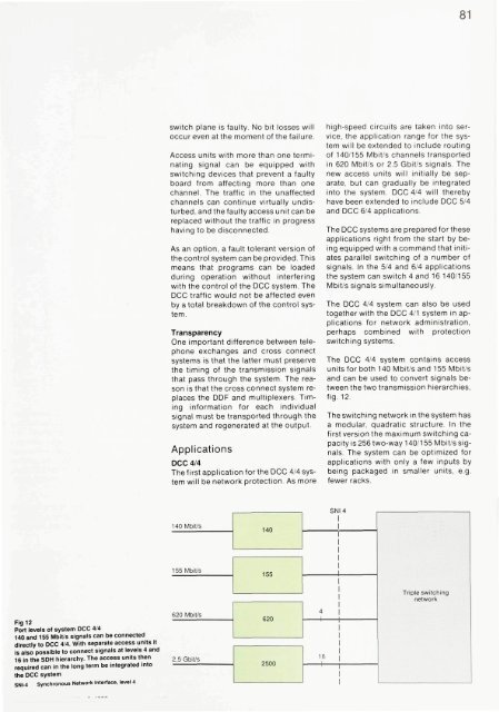
81switch plane is faulty. No bit losses willoccur even at the moment of the failure.Access units with more than one terminatingsignal can be equipped withswitching devices that prevent a faultyboard from affecting more than onechannel. The traffic in the unaffectedchannels can continue virtually undisturbed,and the faulty access unit can bereplaced without the traffic in progresshaving to be disconnected.As an option, a fault tolerant version ofthe control system can be provided. Thismeans that programs can be loadedduring operation without interferingwith the control of the DCC system. TheDCC traffic would not be affected evenby a total breakdown of the control system.TransparencyOne important difference between telephoneexchanges and cross connectsystems is that the latter must preservethe timing of the transmission signalsthat pass through the system. The reasonis that the cross connect system replacesthe DDF and multiplexers. Timinginformation for each individualsignal must be transported through thesystem and regenerated at the output.ApplicationsDCC 4/4The first application for the DCC 4/4 systemwill be network protection. As morehigh-speed circuits are taken into service,the application range for the systemwill be extended to include routingof 140/155 Mbit/s channels transportedin 620 Mbit/s or 2.5 Gbit/s signals. Thenew access units will initially be separate,but can gradually be integratedinto the system. DCC 4/4 will therebyhave been extended to include DCC 5/4and DCC 6/4 applications.The DCC systems are prepared for theseapplications right from the start by beingequipped with a <strong>com</strong>mand that initiatesparallel switching of a number ofsignals. In the 5/4 and 6/4 applicationsthe system can switch 4 and 16 140/155Mbit/s signals simultaneously.The DCC 4/4 system can also be usedtogether with the DCC 4/1 system in applicationsfor network administration,perhaps <strong>com</strong>bined with protectionswitching systems.The DCC 4/4 system contains accessunits for both 140 Mbit/sand 155 Mbit/sand can be used to convert signals betweenthe two transmission hierarchies,fig. 12.The switching network in the system hasa modular, quadratic structure. In thefirst version the maximum switching capacityis 256 two-way 140/155 Mbit/s signals.The system can be optimized forapplications with only a few inputs bybeing packaged in smaller units, e.g.fewer racks.Fig 12Port levels of system DCC 4/4140 and 155 Mbit/s signals can be connecteddirectly to DCC 4/4. With separate access units itis also possible to connect signals at levels 4 and16 in the SDH hierarchy. The access units thenrequired can in the long term be integrated intothe DCC systemSNI-4 Synchronous <strong>Network</strong> Interface, level 4


