pH- and ORP measurement with standard electrodes - Martens ...
pH- and ORP measurement with standard electrodes - Martens ...
pH- and ORP measurement with standard electrodes - Martens ...
- No tags were found...

You also want an ePaper? Increase the reach of your titles
YUMPU automatically turns print PDFs into web optimized ePapers that Google loves.
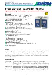
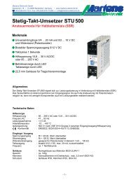
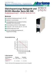
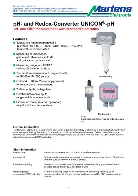
<strong>Martens</strong> Elektronik GmbHKiebitzhörn 18 • D-22885 Barsbüttel/Germany • www.martens-elektronik.deF+49-(0)40-670 73-0 • Fax +49-(0)40-670 73-288 • J info@martens-elektronik.de<strong>pH</strong>- <strong>and</strong> Redox-Converter UNICON ® -<strong>pH</strong><strong>pH</strong>- <strong>and</strong> <strong>ORP</strong> <strong>measurement</strong> <strong>with</strong> st<strong>and</strong>ard <strong>electrodes</strong>ElektronikFeaturesM Measuring range programmable<strong>pH</strong> value <strong>pH</strong>-1.00 ... +15.00, <strong>ORP</strong> -1500 ... +1500mV,temperature compensated,M Monitoring of impedance,glass- <strong>and</strong> reference electrode<strong>and</strong> calibration cycle as wellM Measuring range for <strong>pH</strong>/<strong>ORP</strong>switchable by external signalM Temperature <strong>measurement</strong> programmablefor Pt100 or Pt1000 sensorM Output 4 ... 20mA, 2-wire loop poweredfor temperature <strong>measurement</strong>M 2 alarm outputs, voltage freeM Isolation between output/range-switch input/electrodeM Simulation mode (manual operation)for <strong>pH</strong>, <strong>ORP</strong> <strong>and</strong> temperatureHeadmountingFieldmountingNote:Electrodes <strong>and</strong> fittings must be ordered separatelyGeneral informationThe Converter UNICON-<strong>pH</strong> is used among other things in the food technology, in chemistry, in pharmaceutical industry <strong>and</strong>in the sewage technology. Depending upon structural conditions can be selected between field mounting (electrode <strong>and</strong>converter are mounted seperately) <strong>and</strong> head mounting (electrode <strong>and</strong> converter form one unit). The UNICON-<strong>pH</strong> operates<strong>with</strong> all common <strong>pH</strong>- <strong>and</strong> <strong>ORP</strong>-<strong>electrodes</strong>.Short informationProgrammingAlarm outputElectrode monitoringMeasuring range/measuring <strong>pH</strong>/<strong>ORP</strong> switchingParameters are programmed via front side membrane keypad.Switching performance is programmable as minimum or maximum function. The state ofthe alarm outputs is shown in the LCD-display.One alarm output is selectable for impedance protection of the glass-<strong>and</strong> referenceelectrode against broken glass <strong>and</strong> break of wire.A second measuring range for <strong>pH</strong> or <strong>ORP</strong> can be selected by switching by anexternal control signal. It is also possible to change from <strong>pH</strong> to <strong>ORP</strong> <strong>measurement</strong> <strong>and</strong>reverse.- 1 -
ContentPageTechnical data................................................................................................................................................. 2-3Dimensions......................................................................................................................................................... 3Connection diagrams/terminals....................................................................................................................... 4-6Legend (cover plate) .......................................................................................................................................... 6Controls- <strong>and</strong> display.......................................................................................................................................... 7Installation .......................................................................................................................................................... 7Notes about calibration................................................................................................................................. 8, 22Calibration modes of the UNICON-<strong>pH</strong> ............................................................................................................... 9Programming.................................................................................................................................................... 10Calibration/configure .............................................................................................................................. 10Automatic calibration......................................................................................................................... 11-12Manual calibration............................................................................................................................. 13-15Data calibration ...................................................................................................................................... 16<strong>ORP</strong> calibration ...................................................................................................................................... 16Configuration..................................................................................................................................... 17-20Error codes............................................................................................................................................. 21Mounting notes................................................................................................................................................. 21Replacement of <strong>electrodes</strong> at in-line fittings for head mounting....................................................................... 22Operation notes for <strong>pH</strong> / <strong>ORP</strong> <strong>electrodes</strong> ................................................................................................... 22-23Ordering code................................................................................................................................................... 24Technical dataPower supplySupply voltage: 14 ... 30 V DC, 2-wire, loop poweredOperating temperature : 0 ... 50 °C (32 ... 122 °F)Isolation : <strong>pH</strong> - <strong>and</strong> <strong>ORP</strong> output/temperature output/alarm output 1/alarm output 2/range switch inputTest voltage: 500 V DC- conformity : acc. to EN50022, IEC61000-4-3/4/5<strong>pH</strong> / <strong>ORP</strong>Output signal: 4 ... 20 mABurden: RA [Ω] ≤ Supply voltage -14 V0.02 AMeasuring range: programmable in range <strong>pH</strong>-1.00 ... +15.00 or -1500 ... +1500 mVInput resistance: > 10 12 ΩInput current: < 10 -12 AElectrode zero point : <strong>pH</strong> = 7.00 (Δ<strong>pH</strong> = ± 2.0)Slope: 30 ... 80 mV / <strong>pH</strong>Offset <strong>ORP</strong>: ± 200 mVError: ± 0.2 % of the range or ± 2DigitTemperature coefficient :
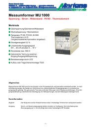
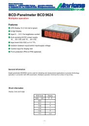
<strong>pH</strong> / <strong>ORP</strong> ConverterType :Input : <strong>pH</strong> / <strong>ORP</strong> electrode; ref. Ag / AgCltemp.-comp. RTD (Pt100 / Pt1000)Power : 14...30V DC / 4...20mA loop-poweredS/N ta50°CTemperature sensor RTD : Pt100 or Pt1000Unit : programmable °C; °FMeasuring range: programmable -40.0 ... +160.0 °C (-40.0 ... +320.0 °F)Min./max. span: 25.0 °C (45.0 °F)/200 °C (360.0 °F)Accuracy: ± 0.1% ± 1 DigitTemperature coefficient : < 50 ppm/°CLinearization error : ± 0.1 %Glass impedance: 0 ... 1 GΩ (temperature compensated)- Measuring range : 0,001 ... 2 GΩ ( not compensated)- Accuracy : ±20 %Reference impedance : 0 ... 100 kΩ (not compensated)- Accuracy : ±20 %Monitoring of the calibrationinterval: 1 ... 1000 daysAlarm outputTransistor outputVoltage dropRange switchInput resistanceRange 1 activeRange 2 active: 14 ... 30 V DC, max. 60 mA, short circuit protection: < 2 V: >10 KΩ: U = 0 ... 3 V DC: U = 12 ... 30 V DCDisplay: LCD-dot matrix, character height 3.8 mm2 lines, 16 characters eachCaseModel: head mounting/field mounting, protection IP65Material : Polyamide <strong>with</strong> fibreglass PA6-GF 15/15Weight: 0.36 kgConnection: Screw terminal <strong>with</strong> pressure plate, 2.5 mm² fine wire, 4 mm² single wireFront keypad: PolyesterDimensions5,54,8100 9010613460Outside brackets(only field case)901002 cable gl<strong>and</strong>s M20x1.5for cable diameter 6-12 mm- 3 -
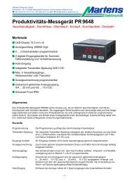
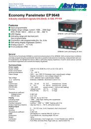
Connection diagrams/terminals1. <strong>pH</strong>-combination electrode<strong>with</strong> integr. temperature sensor2. <strong>pH</strong>-combination electrode<strong>with</strong> ext. temperature sensor3. <strong>pH</strong>-combination electrode<strong>with</strong> <strong>ORP</strong>-electrodeSMEK-7-XX S7-XX SMEK-7-XXType:AL81SL81Type:8100/A8100/CType:AL70APSL9080Type:AL81SL814. <strong>pH</strong>-combination electrode <strong>with</strong> integr.temperature sensor <strong>and</strong> ext. liquid ground5. <strong>ORP</strong>-combination electrode<strong>with</strong> ext. temperature sensorSMEK-7-XXS7-XXType:AL81SL81Type:8100/A8100/CType:AL79Pt8281Terminal description see next page- 4 -
Picture 1 <strong>and</strong> 2Terminal11121314151617Measuring inputTemperature sensor Pt100/Pt1000Temperature sensor Pt100/Pt1000Shield<strong>ORP</strong>-electrode/ liquid groundReference electrodenot usedGlass electrodeSMEK-7-XX*S7-XX*white (WH)green (GN)green/yellow (GN/YE)link to terminal 15black (BK)black (BK)transparent (TR) transparent (TR)Picture 3 <strong>and</strong> 4Terminal11121314151617Measuring inputTemperature sensor Pt100/Pt1000Temperature sensor Pt100/Pt1000Shield<strong>ORP</strong>-electrode/ liquid groundReference electrodenot usedGlass electrodeSMEK-7-XX*white (WH)green (GN)green/yellow (GN/YE)black (BK)transparent (TR)Picture 5Terminal11121314151617Measuring inputTemperature sensor Pt100/Pt1000Temperature sensor Pt100/Pt1000Shield<strong>ORP</strong>-electrode/ liquid groundReference electrodenot usedGlass electrodeS7-XX*transparent (TR)link to terminal 17black (BK)* -XX = cable length [m]- 5 -
Connection diagram / terminalsOpto coupler-outputsmax. 30V DC / 60mAAlarm outputAL2Alarm outputAL1Range switchMR1 MR2Temperature output4 ... 20 mA<strong>pH</strong>/<strong>ORP</strong> output4 ... 20 mA*MR1 MR224 V 24 V 24 V4-20 mA 4-20 mALoadLoad* For supplying the converter use terminals (9) <strong>and</strong> (10) as shown. If the converter is used for monitoring only, terminals(9) <strong>and</strong> (10) must be connected directly to supply voltage.Legend (cover plate)Slide-switch forwrite protectionEEPROMTerminal strip forelectrode connectionDisplay contrastTerminal strip forinput <strong>and</strong> output- 6 -
Controls <strong>and</strong> displayProcess displayAlarm indicator<strong>pH</strong>-valueAlarm output 1(OFF)TemperatureAlarm output 2[ON]Attention!Switching function maxON = limit value oversteppedOFF = limit value fall short offSwitching function minOFF = limit value oversteppedON = limit value fall short offParameter-buttonDown-buttonUp-buttonDescriptionAfter switching on the supply voltage, the converter initializes itself. The display shows messages about the device type<strong>and</strong> software version. After the initializing procedure the converter displays the process values in the working level.Operating of the device is arranged in 2 levels. The requested parameter can be called by the button . Selection <strong>with</strong>ina parameters or entering data, use buttons <strong>and</strong> . Parameters are stored zero voltage safe in the EEPROM.The configuration level is called up by pressing the buttoncan be programmed.. Now all parameters defining the function of the converterAfter finishing the configuration or if longer than 120 seconds no button was pushed, the program returns to the workinglevel. Leaving the configuration level is possible at any time by pushing the button for 2 seconds.Installation note!Before the device can be used, it must be configurated for the intended use.- 7 -
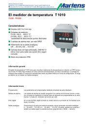
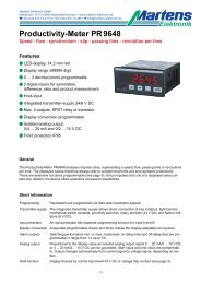
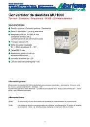
Notes about calibration.In practice the characteristic curves of <strong>pH</strong> <strong>electrodes</strong> deviate from the ideal line. For precise <strong>measurement</strong> it isnecessary to calibrate the UNICON-<strong>pH</strong> on the used <strong>pH</strong>-electrode when setting in operation <strong>and</strong> afterwards inregular time intervals. St<strong>and</strong>ardised <strong>pH</strong> buffer solutions can be used to check measuring points of the connected<strong>pH</strong>-electrode.Maximum operating values for correct <strong>measurement</strong>: Zeropoint 6.0 ... 8.0 <strong>pH</strong>; slope 53.0 ... 59.2 mV/<strong>pH</strong>.Single point calibration:The <strong>pH</strong>-electrode is calibrated <strong>with</strong> one <strong>pH</strong> buffer solution only. The program moves the characteristic curveparallel through the calibration point (see diagram A).- practicable if the <strong>pH</strong> value of the process solution is close to the <strong>pH</strong> value of the buffer solution,no high precision is required <strong>and</strong> the temperature does not fluctuate heavily.Two point calibration:The <strong>pH</strong>-electrode is calibrated <strong>with</strong> 2 buffer solutions. The exact characteristic curve is determined. The programcalculates the deviation from the ideal characteristic curve (see diagram B).- This calibration is recommended if the <strong>pH</strong> value or the temperature of the process solution fluctuates heavily<strong>and</strong> high precision is required.Diagram ADiagram BSingle point-calibration<strong>with</strong> buffer <strong>pH</strong>7.00Two point-calibration<strong>with</strong> buffer <strong>pH</strong>4.01 <strong>and</strong> <strong>pH</strong>10.00Characteristicafter calibrationReal characteristicof the electrodeStored charactristic(factory setting orfrom previous calibrationcalibration pointStored charactristic(factory setting orfrom previous calibration)Calibrated characteristic= real characteristic1. calibration pointBy the translation of thecalibrated characteristiconly the zero pointchanges2. calibration point- 8 -
Calibration modes of the UNICON-<strong>pH</strong>1.) Automatic calibration (parameter 3 = Auto)Using one of the st<strong>and</strong>ardised <strong>pH</strong> buffer solutions sets listed in the technical data (page 2) the UNICON<strong>pH</strong>automatically calculates the parameters of the connected <strong>pH</strong> electrode. The automatic calibrationcan be accomplished only <strong>with</strong> sensors <strong>with</strong> integrated temperature sensor. Parameter 51 must be set toPt100 or Pt1000In this calibration mode also <strong>with</strong> aged <strong>pH</strong> <strong>electrodes</strong> the used buffer will be recognized, if their zero-pointmay not have shifted no more than ±1.0<strong>pH</strong>. For example, if a buffer <strong>with</strong> 4<strong>pH</strong> is used, the measured valuemay be in the range of 3.0 up to 5.0<strong>pH</strong>. The buffer is not recognized surely, if the measured valuefalls below this or exceeds this values <strong>and</strong> the automatic calibration will be stopped.Thus the electrode did not become useless but the large deviation points to a strong aging. A manual calibrationis still possible in most cases.2.) Manual calibration (parameter 3 = Manual)For manual calibration it is possible to choose a buffer from the st<strong>and</strong>ardised buffer solution sets or to enterthe buffer value manually.Manual calibration is recommend also, if the automatic calibration is not possible. In contrast to the automaticcalibration during the manual calibration the buffers are not reconized automatically. Through thisrestriction of the maximum deviation to ±<strong>pH</strong>1,0 is dropped. If the <strong>measurement</strong> differs more than±<strong>pH</strong>3,0 the electrode must be replaced.3.) Data input (parameter 3 = Data)The parameters zero <strong>and</strong> slope of the attaced electrode are known <strong>and</strong> entered directly.Required solutions:- Buffer solutions according to the desired method of calibration.- Tap water for rinsing the electrode.- 9 -
ProgrammingNotes to representationError messagesParameter only appears at appropriate model (see order code)Parameter-button for parameter selection or storing of the valuesUp- <strong>and</strong> Down-buttons for selection or entering values in the parameter levelNote! During the configuration only those parameters will be displayed, which are not excluded by other parameter settingsor if they are available in the device.Calibration/configuration<strong>pH</strong>10.54 AL1Q25.7°C AL2OProcess value for <strong>pH</strong>- or <strong>ORP</strong>- <strong>and</strong> temperature-valuesAlarm output indication (only if activated)Q = OFF <strong>and</strong> O = ON.If collective alarm SAL is activated, the display toggles between error massage <strong>and</strong> processvalue.1OCalibrationQConfigurationCalibrationConfiguration: the connected electrode shall be calibrated.: the converter shall be configured.CalibrationConfigurationcontinue page 17parameter 392O<strong>pH</strong> calibr.Q<strong>ORP</strong> calibr.This parameter only appears for model 2,if MR1 = <strong>pH</strong> und MR2 = <strong>ORP</strong>.<strong>pH</strong> calibration3Calib.? OAutoQManual QData<strong>ORP</strong> calibrationcontinue page 16parameter 35/36Selection of the calibration modeAuto : automatic buffer detection.Manual : manual input of the buffer values.Data : input of zero-point <strong>and</strong> slope.$ The manual calibration is recommended for older <strong>electrodes</strong>.Auto Manual Datacontinue page 11parameter 4continue page 13parameter 15continue page 16parameter 33- 10 -
Automatic calibration4Select buffer setWTW 5Dip <strong>pH</strong> electrodeinto 1.bufferBuffer set$ Only for <strong>electrodes</strong> <strong>with</strong> integrated temperature sensornominal <strong>pH</strong>-values of the buffersWTW4.01/7.00 at 0...95 °C/10.00 at 0...50 °CSchott4.00/7.00/10.00 at 0 ... 40 °CIngold (Mettler Toledo) 4.01/7.00/9.21 at 0 ... 95 °CDIN192664.01/6.87/9.18 at 0 ... 95 °CRinse the electrode in tap water <strong>and</strong> immerse in the 1. buffer solution.Start the calibration <strong>with</strong> button .61.buffer temp.23.6°C /Temperature measuring of the 1. <strong>pH</strong>-buffer solution.A rotating bar indicates the measuring process. If the bar stops , the measured valueis taken over <strong>and</strong> the calibration procedure will be continue <strong>with</strong> the next parameter.It is possible to stop the <strong>measurement</strong> during the measuring process, <strong>with</strong> buttonat any time <strong>and</strong> the current value will be stored.Temp.not const.Qnext Obacknext ► Parameter 7back ► Parameter 67Nom. val. <strong>pH</strong>7.0623.6°C 10sMeasuring of the 1. bufferAs soon as the measured value is constant, this is taken over as first calibration parameter.The calibration procedure continues <strong>with</strong> parameter 8.<strong>pH</strong>-<strong>measurement</strong>not const.4sUse manualcalibrationNo constant value<strong>with</strong>in 3min.<strong>pH</strong>-electrodeDifference><strong>pH</strong>1.04sUse manualcalibrationDifference of current valueto buffer > <strong>pH</strong>1.0Buffer temp.to lowBuffer temperature out of range.8Buffer <strong>pH</strong>7.00Difference <strong>pH</strong> 0.1The nominal value of the identified buffers<strong>and</strong> the difference to the actual value will bedisplayed.$ The measured values arenot talken overback to parameter 1page 1092.buffer calib.?OYESQNOYESNO: 2-point-calibration.A 2. buffer solution has to be measured.: 1-point-calibration.The calibration procedure is finishedYESNOcontinue page 12parameter 10continue page 12parameter 14- 11 -
10Dip <strong>pH</strong> electrodeinto 2.bufferRinse the electrode in tap water <strong>and</strong> immerse in 2. buffer solution.Start the calibration <strong>with</strong> button .112.buffer temp.25.7°C /Temperature measuring of the 2. <strong>pH</strong>-buffer solution.A rotating bar indicates the measuring process. If the bar stops, the measured valueis taken over <strong>and</strong> the calibration procedure will be continue <strong>with</strong> the next parameter.During the measuring process, it is possible to stop the <strong>measurement</strong> <strong>with</strong> buttonat any time <strong>and</strong> the actual value will be stored.Temp.not const.Qnext Obacknext ► Parameter 12back ► Parameter 1112Value <strong>pH</strong> 4.2125.7°C 15sMeasuring of the 2. bufferAs soon as the measured value is constant, this is taken over as first calibration parameter.The calibration procedure continues <strong>with</strong> parameter 13.<strong>pH</strong>-<strong>measurement</strong>not const.4sUse manualcalibrationNo constant valueduring 3min.<strong>pH</strong>-<strong>measurement</strong>Difference><strong>pH</strong>1.04sUse manualcalibrationDifference of act. valueto buffer > <strong>pH</strong>1.0Buffer temp.to lowBuffer temperature out of range.Same bufferor short circuitDifference from buffer 1 tobuffer 2 is to small.Calib. invalidSlope
Manual calibration15Sel. buffer setWTW Buffer setnominal <strong>pH</strong>-values of the buffersWTW4.01/7.00 at 0...95 °C/10.00 at 0...50 °CSchott4.00/7.00/10.00 at 0 ... 40 °CIngold (Mettler Toledo) 4.01/7.00/9.21 at 0 ... 95 °CDIN192664.01/6.87/9.18 at 0 ... 95 °CSpecial buffer Manual buffer input16Temp. for Calib.OMan QPt100/1000Selection of the temperature <strong>measurement</strong>.For calibration of <strong>pH</strong>-<strong>electrodes</strong> <strong>with</strong>out integrated temperature sensor, selectMan <strong>and</strong> use an ext. thermometer.17Dip <strong>pH</strong> electrodeinto 1.bufferRinse the electrode in tap water <strong>and</strong> immerse in the 1. buffer solution.Start the calibration <strong>with</strong> button .18Manual temperature inputEnter temp.22.0°CManual input of theof the buffer soulutiontemperatureTemperatureconstant19Automatic temperature <strong>measurement</strong>1.buffer temp.21.2°C /Temperaturenot constantTemperature <strong>measurement</strong>of the 1. <strong>pH</strong>-buffer solution.A rotating bar indicates themeasuring process. It is possibleto stop the <strong>measurement</strong>during the measuringprocess, <strong>with</strong> button atany time <strong>and</strong> the current valuewill be stored.Temp.not const.Qnext Obacknext ►Parameter 20/21(reduced accuracy)back ►Parameter 1920Buffer setSelect 1.buffernom. val. <strong>pH</strong> 4.001.Buffer selection21Special buffer1.buffer at21.2°C-> <strong>pH</strong> 4.01Input of the buffer value accordingto the <strong>pH</strong>/temperaturetable.Buffer temp.to lowback to parameter 1page 10$ The measured values arenot taken overcontinuepage 14- 13 -
22Value <strong>pH</strong> 2.7621.2°C11sMeasuring of the 1. bufferThe next parameter will be selected if the measuring value is constant. During themeasuring process, it is possible to stop the <strong>measurement</strong> <strong>with</strong> button at any time<strong>and</strong> the current value will be stored. The calibration accuracy is reduced.Value not const.Qnext Obacknext ► parameter 23back ► parameter 2223<strong>pH</strong>-electrodeout of operationBuffer <strong>pH</strong> 4.01Difference <strong>pH</strong>-1.24sDeviation of zero-point ><strong>pH</strong>3.0.The electrode must be replaced.Measurementmay be faultyback to parameter 1page 10The calculated buffer <strong>and</strong> the difference to the measuredvalue are displayed.The message " <strong>measurement</strong> may be faulty " appears,if the deviation ><strong>pH</strong>2.0.Abort calib.?QYESONOIf the difference exceeds ><strong>pH</strong>2.0, the calibration can be stopped.Parameter zero-point <strong>and</strong> slope are not changed.YES : continue page 10, process displayNO : continue parameter 24242.buffer calib.OYES QNOYESNO: 2-point-calibration.A 2. buffer solution has to be measured.: 1-point-calibration.The calibration procedure is finished25YESDip <strong>pH</strong> electrodeinto 2.bufferNOcontinue page 15parameter 32Rinse the electrode in tap water <strong>and</strong> immerse in the 2. buffer solution.Start the calibration <strong>with</strong> button .26Manual temperature inputEnter temp.22.0°CManual temperature inputof the buffer solution.27Automatic temperature <strong>measurement</strong>2.buffer temp.22.7°C /Temperature measuring of the 2.<strong>pH</strong>-buffer solution.A rotating bar indicates the measuringprocess. It is possible to stopthe <strong>measurement</strong> during the measuringprocess, <strong>with</strong> button atany time <strong>and</strong> the current value willbe stored.continuepage 15Temp.not const.Qnext Oback- 14 -next ► parameter 28/29(reduced accuracy)back ► parameter 27
28Buffer setSelect 2.Puffernom.val. <strong>pH</strong> 7.00Special buffer292. buffer selection Input of the buffer value acc. to2.buffer atthe <strong>pH</strong>/temperature table.22.7°C-> <strong>pH</strong> 7.02Buffer temp.to lowBuffer temperatureout of range.Same inputas buffer 1Difference1. buffer to 2. buffer< <strong>pH</strong> 1.0.back to parameter 1page 10$ The measuredvalue are not takenover.30Value <strong>pH</strong> 5.6122.7°C15sMeasuring of the 2.bufferThe next parameter will be selected if the measuring value is constant. During the measuringprocess, it is possible to stop the <strong>measurement</strong> <strong>with</strong> button at any time <strong>and</strong> thecurrent value will be stored. The calibration accuracy is reduced.Value not const.Qcont. Obackcont. ► parameter 31back ► parameter 30Same bufferor short circuitDifference from 1.buffer to2.buffer is to small.$ The measured valueare not taken over<strong>pH</strong>-electrodeout of operationDeviation of zero-point ><strong>pH</strong> 3.0 orslope<strong>pH</strong> 2.0.Abort calib.?QYESONOIf the difference exceeds <strong>pH</strong> 2.0, the calibration can be stopped.Parameter zero-point <strong>and</strong> slope are not changed.YES : back to the process display page 10.NO : continue parameter 32.32Zero <strong>pH</strong> 8.49Slope 55.9mV/<strong>pH</strong>The manual calibrieration is finished.The electrode values are displayed <strong>and</strong> should be recorded.back to the process displaypage 10- 15 -
51Temp.SensOPt1000QMan.QPT100Selection of the temperature <strong>measurement</strong>Man. : manual inputPt1000 : <strong>measurement</strong> <strong>with</strong> Pt1000 SensorPt100 : <strong>measurement</strong> <strong>with</strong> Pt100 Sensor52ManMan.temp.25.0°CManual input ofthe temperature(for <strong>electrodes</strong><strong>with</strong>out sensor).53Pt1000/Pt100Temp. init value0.0°CTemperature measuring rangeinitial value (for 4mA).Setting possible in the range-40.0 ... 135.0°C (-40.0 ... 275.0°F).54Temp. end value100.0°CTemperature measuring rangeend value (for 20mA).Setting possible in the range-15.0 ... 160.0°C (5.0 ... 320°F).Minimum span 25.0°C (77.0°F)55Temp. Offset0.0°C -> 25.3°CProcess value temperature offset.Setting possible in the range-12.8 ... 12.7°C (8.96 ... 54.86°F) .The display shows the offset at the leftposition <strong>and</strong> the corrected value at theright position.56Alarm AL1 OOFFQMR1 QMR2 QMRTAlarm function AL1.The alarm AL1 can be deactivated or assigned to the <strong>measurement</strong> range 1, 2 or the temperature.$ If parameter 51 = Man. (manual temperature input) point MRT is not availabe.OFF57Alarm AL1QMINMR1, MR2, MRTOMAXSwitching performance AL1.58Setpoint AL1<strong>pH</strong> 0.00Setpoint AL1.Setting possible in the selected measuringOFF59Hysteresis AL1<strong>pH</strong> 0.01Hysteresis AL1.Setting possible in the range 1 ... 3000 DigitHysteresis to maximum = hold functioncontinuepage 19- 18 -
60Alarm AL2 OOFFQMR1 QMR2 QSALAlarm function AL2.The alarm AL2 can be deactivated or assigned to the <strong>measurement</strong> range 1 or 2 or to collectivealarm (SAL).$Settings for switching performance, setpoint <strong>and</strong> hysteresis of the alarm outputs areidentical for AL1 <strong>and</strong> AL2 if MR1 or MR2 is selected.Collective alarm61MAX glass imped.QOFFOONIf an error occurs the depending alarm-message is displayed in the process display.Monitoring of the maximum glass impedance (for example break of wire).62Glasimp.SetpntMAX38MΩ200MΩSetpoint of the maximum glass impedance.The currently measured impedance of the glass electrode is displayed in the first line.The second line displays the setpoint (MAX Point)Setting possible in the range 1...1000 MΩ63MIN glass imped.OOFF QONMonitoring of the minimum glass impedance (for example shorted line or break of glass).64Glasimp.SetpntMAX38MΩ5MΩSetpoint of the minimum glass impedance.The currently measured impedance of the glass electrode is displayed in the first line. Thesecond line displays the setpoint (MIN Point)Setting possible in the range 1...1000 MΩ. It is recommended to program a 1/5 of the measuredimpedance65MAX ref. imp.OOFF QONMonitoring of the maximum reference impedance(only possible <strong>with</strong> connected liquid ground).Monitoring of dirty diaphragm.66Refimp. 9.8kΩSetpntMAX 50.0kΩSetpoint of the maximum reference impedance.The currently measured impedance of the glass electrode is displayed in the first line. Thesecond line displays the setpoint (Max Point)Setting possible in the range 0.1...100.0 kΩ. It is recommended to program 5-times the valueof the measured impedance.67Calib. interval100Tg-> 50TMonitoring of the calibration interval.Setting possible from OFF, 1 ... 1000 days.Left area shows calibration interval.Right area shows the remaining days of the interval.continuepage 20- 19 -
68Simulation MR1<strong>pH</strong>7.0069Simulation temp.0.0°CSimulation of the <strong>pH</strong>- or <strong>ORP</strong> value (manual operation).Start value = current value.Setting possible in preselected measuring range.This parameter will not be left automatically after 120 seconds.Simulation of the temperature (manual operation).Start value = current value.Setting possible in the preselected measuring range.This parameter will not be left automatically after 120 seconds.70Adjust 4-20mAQYESONOCorrection of the analog process outputs.NO71YESCorr.outp.<strong>pH</strong>/RedInitial: 4.00mACorrection initial value of the analog output for <strong>pH</strong> or <strong>ORP</strong>value.Setting possible in the range 3.70 ... 7.50 mA72Corr.outp.<strong>pH</strong>/RedEnd: 20.00mACorrection final value of the analog output for <strong>pH</strong> or <strong>ORP</strong> value.Setting possible in the range 16.80 ... 21.00 mA73Corr.outp.Temp.Initial: 4.00mACorrection final value of the analog output for <strong>pH</strong> or <strong>ORP</strong> value.Setting possible in the range 16.80 ... 21.00 mA74Corr.outp.Temp.End: 20.00mACorrection of the end value of the analog temperature output.Setting possible in the range 16.43 ... 20.60 mA75UNICON - <strong>pH</strong>Version X.XXSoftware version76ConfigurationQlock OunlockProgram lockout.If this parameter is activated, only the setpoints of the alarm outputs AL1 <strong>and</strong> AL2 will bedisplayed. To change the parameter press the button or for at least. 2 seconds.77Factory settingCode=00Only for factory settings.back to the process displaypage 10- 20 -
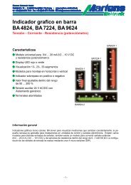
Error messagesError! Factorycheck necessaryMemory error.Factory check is necessaryWrite protect !!A changed parameter setting cannot be stored, because the write protection is activatedby intern slide switch in position 1. Set the switch to position 0 <strong>and</strong> modify settings again.Transm.errorRAMEEPROMAn error has occurred in the data transfer from the controller to the EEPROM, or the datain the EEPROM are damaged .after 2 secondsTransm.errorfor Init RAMWith the button a new initialisation of the EEPROM can be triggered. The factory <strong>and</strong>calibration settings get lost. The converter works <strong>with</strong> a reduced precision <strong>and</strong> should benew calibrated in the factory. All programmed values get lost.ResetUNICON - <strong>pH</strong>Version X.XXThe converter triggers an internal reset. An attempt is made to read data from theEEPROM.Mounting notesBasically its recommended that there is no air between the active area of the electrode <strong>and</strong> the measuring solution.While installing a system <strong>with</strong> UNICON-<strong>pH</strong> head mounting, it may be necessary to turn converter <strong>and</strong> fitting against eachother for easy operation <strong>and</strong> better reading of the display. These assembly variations are possible in steps of 30°.In order to turn the case against the fitting position, please proceed asfollows:Open the converter by releasing the 4 cover screws..Unscrew the nut of the connection converter <strong>and</strong> fittingSeparate the converter from fitting <strong>and</strong> place it in the desired Position.Please make sure that the turning lock will click in none of the holesTurning lockFittingTighten the nut of the connection converter <strong>and</strong> fitting.- 21 -
Replacement of <strong>electrodes</strong> in fittings for head mounting.<strong>pH</strong>- <strong>and</strong> <strong>ORP</strong> <strong>electrodes</strong> have a limited life. For replacement operate as follows:Open the converter by releasing the 4 cover screws.Disconnect connection cable (SMEK-6-K or S7-K) from the terminals11-17 on the circuit board.Unscrew the body of the fitting <strong>and</strong> head-adapter.Remove the screwed plug of the connection cable from the electrode.Unscrew the electrode out of the fitting <strong>with</strong> a spanner (SW17).Case bodyConverter UNICON-<strong>pH</strong>Plug connection cable(SMEK-6-K or S7-KHead adapterSW17ElectrodeBody of fittingOperating Instruction for <strong>pH</strong>/<strong>ORP</strong>- <strong>electrodes</strong>Delivery<strong>and</strong> shippingStorageRefreshingThe <strong>electrodes</strong> are supplied <strong>with</strong> a protection cap filled <strong>with</strong> a 3-mole KCl-storagesolution. This cap prevents a draining of the electrode.The <strong>electrodes</strong> should be stored <strong>with</strong>in the temperature range -5...+30 °C. Otherwise they can bedamaged irreparably, by temperatures under -5 °C. In order to avoid a draining of the <strong>electrodes</strong>,these should be stored <strong>with</strong> the associated protective cap. With longer storage time, the level of liquidof the cap is to be examined. A storage time longer than 1 year is not recommendable.Dried <strong>electrodes</strong> normally can be regenerated, but they will never achieve the original conditions.Therefor the electrode must be stored in a 3-mole KCl-solution for 24 hours. If the electrode shouldbring thereafter still no satisfying values, a heating up to 60-80° in a water bath cancleanse a possibly blocked up diaphragm.The <strong>electrodes</strong> <strong>with</strong> liquid reference must to be filled up.- 22 -
During adjustment of the cable length, the black insulating of the coax lead must be re-moved.<strong>pH</strong>-<strong>electrodes</strong> have a high internal resistance. Humidity at the connection plug must be avoided(danger; creeping current). Don’t touch the contacts of the plug while removing the plug protectioncap. Transition resistance lead to an erroneous <strong>measurement</strong>.Take off the Protection cap <strong>and</strong> rinse off possible salt incrustations. Electrodes <strong>with</strong> liquid electrolytefor the reference electrode must be possibly refilled. Electrodes <strong>with</strong> gel filling may not be opened,protecting covers may not be shifted. If there are some bubbles at the front measuring area,they are removable by shaking the electrode (like a fibre thermometer).Preparingfor MeasurementCalibrationMountingIn practice the characteristic curves of the <strong>pH</strong> electrode deviate from the ideal line. For precise<strong>measurement</strong> it is necessary to calibrate the <strong>pH</strong>-electrode during commissioning <strong>and</strong> after regulartime intervals.It is common to calibrate the electrode <strong>with</strong> a 2-point-calibration for zero-point <strong>and</strong> the slope.The value of the buffer-solution should be nearly at the measuring value of the process. For higherprecision it is recommended to heat the solution to the process temperature. Alkaline bufferchange theire value while picking up CO2 from the air. Acid buffer are ideal because they have ahigher stability. For the best result it´s recommend to calibrate <strong>with</strong> buffer-solution <strong>pH</strong>4.00 <strong>and</strong><strong>pH</strong>7.00. The buffer solutions should be used only once.Before dipping the electrode into the buffer solution, it must be rinsed <strong>with</strong> water <strong>and</strong> dabbed <strong>with</strong>clean fleece cloth. Each pollution of the buffer solution can change their value, <strong>and</strong> worsen theaccuracy of the calibration.It is very important to mount the electrode immediately before starting up the system, to protectthe electrode against drainage.For the mounting it necessary to use a 17mm ring- or mouth spanner. Other tools will damage theglass protection sheath.Mounting pos.The mounting direction should be in range 10° <strong>and</strong> 170° from the vertical positionYESNOCleaning <strong>and</strong>maintenanceDirty <strong>electrodes</strong> supply incorrect results of <strong>measurement</strong>. Therefore they should be cleanedin regular intervals. In order not to damage the <strong>electrodes</strong>, the glass diaphragm should not bescratched or scouring agents treated.- rough contamination are dabbed <strong>with</strong> a fleece cloth.- oily <strong>and</strong> greasy contamination are eliminated <strong>with</strong> household cleaner (no scrubbing means).- calcifying are solved by diluted hydrochloric acid.- Protein contamination are solved <strong>with</strong> hydrochloric acid <strong>and</strong> pepsin mixture.- contamination of sulfide can be separated in a mixture from hydrochloric acid <strong>and</strong> thiourea.- 23 -
<strong>Martens</strong> Elektronik GmbHKiebitzhörn 18 • D-22885 Barsbüttel/Germany • www.martens-elektronik.deF+49-(0)40-670 73-0 • Fax +49-(0)40-670 73-288 • J info@martens-elektronik.deElektronikOrdering codeUNICON-<strong>pH</strong> -1. 2. 3. 4.- - - -1. Model1 Output 4 ...20 mA, 2-wire loop poweredfor <strong>pH</strong>- und <strong>ORP</strong>,2 transistor alarm outputs,supply voltage 14 ... 30 V DC,2 as 1, but additional2. measuring range for <strong>pH</strong> <strong>and</strong> <strong>ORP</strong>,output temperature 4 ... 20 mA, 2-wire loop powered,monitoring impedance of the glass <strong>and</strong>reference electrode <strong>and</strong> the calibration interval as well.2. Mounting01 Head mountingAssembly of the UNICON-<strong>pH</strong> directly on the fitting of the electrodeConnection of the electrode <strong>with</strong> a separate connection cableSMEK-6K (see separate data sheet)02 Field mountingNote: Inline fittings, combination <strong>electrodes</strong> <strong>and</strong> connection cablemust be ordered separately (see separate data sheet)3. Reference system3 all systems <strong>with</strong> electrode zero point <strong>pH</strong> 7.00e.g. silver/silver chloride (Ag/AgCl)4. Temperature <strong>measurement</strong>13 Pt1000/Pt100 Sensor via software selectableFurther information about <strong>pH</strong>- <strong>and</strong> <strong>ORP</strong>-measuring systems-combination <strong>pH</strong>- <strong>and</strong> <strong>ORP</strong> <strong>electrodes</strong>-Pt1000 temperature sensor-in-line fittings-accessories for conductivity <strong>and</strong> <strong>pH</strong>/<strong>ORP</strong> <strong>measurement</strong>please contact us.02/06-V1.20-01- 24 -