å· MA0083RKY - Kitagawa Europe
å· MA0083RKY - Kitagawa Europe
å· MA0083RKY - Kitagawa Europe
- No tags were found...

Create successful ePaper yourself
Turn your PDF publications into a flip-book with our unique Google optimized e-Paper software.
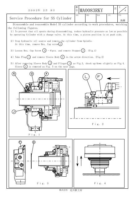
2002 年 2 月 8 日番号 <strong>MA0083RKY</strong>頁14Service Procedure for SS Cylinder部 長 課 長 係 長 主 任 作 成Disassemble and reassemble Model SS cylinder according to work procedures, watchingthe following figures.1)To prevent that oil spouts during disassembling, reduce hydraulic pressure as low as possibleby operating Cylinder with a change valve. At this time, a piston position is at push side.2)Stop hydraulic oil source and remove the cylinder from Spindle.At this time, remove Hex. Cap screw 4 .池 藤3)Loosen Hex. Cap Screw 5 -6pcs. and remove Stopper J .(Fig.1)4)Take Plug L and remove Sleeve Body F in the arrow direction. (Fig.2)5)After removing Sleeve Body F and Flinger N as Fig.3, shock up/down slightly as Fig.4.Sleeve G is removed as Fig. 5 on the next page.Fig.2Fig.1Fig.3Fig.4株 式 会 社 北 川 鉄 工 所
2002 年 2 月 8 日番号 <strong>MA0083RKY</strong>頁24部 長 課 長 係 長 主 任 作 成池 藤SLEEVE ASSYFig.5ROTARY VALVE ASSY6) Loosen Hex. Cap Screw 3 -12pcs. and separate Rotary Valve E & Piston Housing D andremove Piston H by using the tap holes located on Rotary Valve E (Fig.7).At this time, markon both Rotary Valve and Piston Housing with Marker to match the position.Rotary Valve E , Lock Valve A and B , Piston H and Piston Housing D are separatedinto.(At this time, be careful that the oil in Piston Housing spills.)(Fig.6,8)Disassembling is completed.Fig.6Fig.7株 式 会 社 北 川 鉄 工 所
2002 年 2 月 8 日番号 <strong>MA0083RKY</strong>頁34部 長 課 長 係 長 主 任 作 成池 藤Fig.8Assembling procedures are described from here.7)Incorporate Lock Valve A and B and Piston H inPiston Housing Rotary Valve E .At this time, be sure the positions for Lock ValveA and B (Fig.8)8)Incorporate O-ring 6 in Piston Housing D andInsert Piston H and Rotary Valve E into PistonHousing D and slightly fasten Hex. Cap Screw 3After mating the positions between O-ring 6 andPlug M located on Rotary Valve E .(Fig.6, 9)9)Mount the above once as it is on the Spindle andmake the alignment so that run-out between PistonHousing D and Rotary Valve E becomes as smallas possible. Then fasten them with Hex. Cap Screw3 . ( Target run-out: 0.01TIR)(Fig.10)Fig.9Fig.10株 式 会 社 北 川 鉄 工 所