S type - Kitagawa Europe
S type - Kitagawa Europe
S type - Kitagawa Europe
- No tags were found...

You also want an ePaper? Increase the reach of your titles
YUMPU automatically turns print PDFs into web optimized ePapers that Google loves.
The resolution / an assemblingwork procedureS <strong>type</strong>HIGH SPEED ROTARY HYDRAULICCYLINDER OPEN CENTERCAUTION・ Please send back to <strong>Kitagawa</strong> Iron Works Co., LTD. or the shop and do therepair and the component replacement of the cylinder.・ When resolving and assembling it again, consumption part exchanges such aso-ring, oil seals, bearings and balance correction in rotation part and centering ofeach part, the work such as fine-tuning is generated, too.・ When neither the repair nor the component replacement in <strong>Kitagawa</strong> Iron WorksCo., LTD. and the shop are done, all guarantees become invalid.
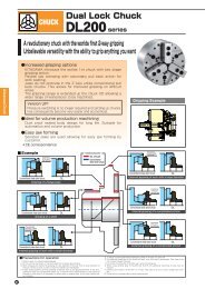
DATE 18 DEC 2008 № MA0534RKY P14The resolution / an assembling work procedureFor S <strong>type</strong> cylinderMANAGER CHIEF WRITE BY高 橋 優Please take apart and assemble the S <strong>type</strong> cylinder referring to figure based on the work procedure.1 ) Please drop the hydraulic pressure power to the low pressure as much as possible while operatingthe cylinder with the change-over valve to prevent hydraulic from spouting when the cylinder istaken apart. (Please push and stop it the piston on the side at this time.)2 ) The hydraulic pressure source is stopped, and the cylinder is detached from the spindle.3 ) Cross-recessed head machine screw 14 4 pieces are loosened and fan-cover J is removed.Cross-recessed head machine screw 4 pieces (S1246 and S1875 is 3 pieces) in fan-cover areloosened and the fan K is removed. (Fig. 1)4 ) Socket head cap screw 02 12 pieces (S1552 and S1875 is 6 pieces) are loosened and thestopper L is removed. (At this time, it is possible to remove easily by using the tap of the stopperL .) Please remove sheat-packing (C) N to S2091 or more at the same time. Moreover, pleasethis sheat-packing (C) N might be damaged, and assemble and prepare the new article at times.(Fig. 1)5 ) Flinger P is pulled out and the plug R is loosened, and the sleeve-body F is removed in thedirection of the arrow. (Fig. 2)Fig. 1Fig. 2Fig. 3 Fig. 4KITAGAWA IRON WORKS CO., LTD.
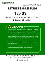
DATE 18 DEC 2008 № MA0534RKY P24The resolution / an assembling work procedureFor S <strong>type</strong> cylinderMANAGER CHIEF WRITE BY高 橋 優SleeveFig. 5Rotary valve6 ) It makes as shown in Fig. 3, and the sleeve body F are removed. Afterwards, please make thecylinder as shown in Fig. 4 and give an upper and lower impact slightly.The sleeve G is removed, it falls, and it is resoluble as shown in figure on the this page. (Fig. 5)7 ) Socket head cap screw 03 12 pieces or 16 pieces are loosened, the cylinder D is removed byusing the tap for pulling out (Fig. 7) that exists in the rotary valve E and the piston H is pulledout. At this time, please be suitable for the cylinder and rotary valve in the marker etc. and fill in themark. It divides into the rotary valve E , the piston H , and the cylinder D . (Please note that thehydraulic enclosed in the cylinder this time flows out.)(Fig. 6 and 8)It is resolution completion in this.Fig. 6 Fig. 7KITAGAWA IRON WORKS CO., LTD.
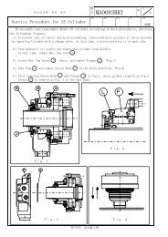
DATE 18 DEC 2008 № MA0534RKY P34The resolution / an assembling work procedureFor S <strong>type</strong> cylinderMANAGER CHIEF WRITE BY高 橋 優Fig. 8The assembly work procedure is shown here.8 ) The position H of guide-pin Q 2 pieces is matchedand the piston is built into the rotary-valve E .(Fig. 7)9 ) O-ring 04 is built into the cylinder D . The piston Hand rotary valve E are inserted in the cylinder D , itmatches, the position with the plug S in outer of O-ring04 and rotary valve E is built, and it tightens with thesocket head cap screw 03 lightly.(Please be suitable and confirm it by the mark.)(Fig. 6and 9)10 ) Under such a condition, please install it in the spindleonce. And, please do the wick match so that run-out ofthe cylinder D and rotary valve E may become smallas much as possible. Afterwards, please tighten with thesocket head cap screw 03 .(run-out must aim at 0.01TIR or less.)(Fig. 10)Fig. 9Fig. 10KITAGAWA IRON WORKS CO., LTD.
DATE 18 DEC 2008 № MA0534RKY P44The resolution / an assembling work procedureFor S <strong>type</strong> cylinder11 ) The cylinder is unloaded from the spindle, and thesleeve is inserted from the rear side of rotary valveE . It enters smoothly when doing while lightlybeating with the hammer etc. with a ring form specialjig in a right picture. At this time, please build it innoting that the sleeve doesn't twist. (Fig. 11)MANAGER CHIEF WRITE BY高 橋 優12 ) Flinger N is inserted in rotary valve E . Afterwards,please arrange the plug insertion hole and thedirection of the sleeve G and build in the sleeve bodyF .13 ) The plug L is wrung. (Fig. 2)14 ) The stopper L is installed with the socket head capscrew 02 . (Please insert S2091 or more withoutforgetting sheat-packing (C).)(Fig. 1)15 ) The fan K and fan-cover J are obtained with aCross-recessed head machine screw 14 、20 . (Fig. 1)16 ) After assembly, the cylinder is installed in the spindleaccording to the above-mentioned procedure.Afterwards, please adjust it so that run-out at theinstallation may become 0.015TIR or less by outer ofrotary valve E and 0.01TIR or less by outer ofsleeve body F .Fig. 1117 ) Please use it after laying pipes after assembly iscompleted and confirming operation.Notes of assembly・ When O-ring and the oil seal are damaged, it causes the oil leakage. Therefore, please assemble itmight not spread oil enough on the sliding area and each part O-ring, and to damage it.・ At assembly, When garbage etc. enter in the cylinder it causes overheating. Please assemble itvery carefully.KITAGAWA IRON WORKS CO., LTD.