BELIMO-LF24SR - NCA Manufacturing
BELIMO-LF24SR - NCA Manufacturing
BELIMO-LF24SR - NCA Manufacturing
- No tags were found...

Create successful ePaper yourself
Turn your PDF publications into a flip-book with our unique Google optimized e-Paper software.
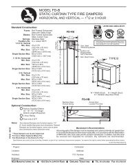
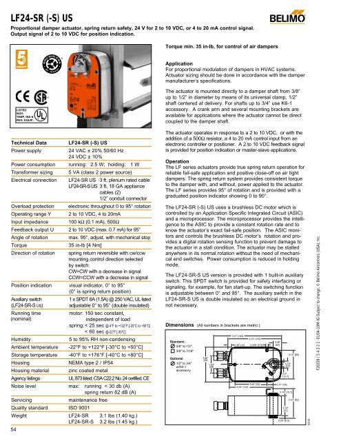
LF24-SR (-S) USProportional damper actuator, spring return safety, 24 V for 2 to 10 VDC, or 4 to 20 mA control signal.Output signal of 2 to 10 VDC for position indication.LISTED94D5TEMP. IND ®. EQUIP.®Torque min. 35 in-lb, for control of air dampers©ApplicationFor proportional modulation of dampers in HVAC systems.Actuator sizing should be done in accordance with the dampermanufacturer’s specifications.The actuator is mounted directly to a damper shaft from 3/8”up to 1/2” in diameter by means of its universal clamp, 1/2”shaft centered at delivery. For shafts up to 3/4” use K6-1accessory. A crank arm and several mounting brackets areavailable for applications where the actuator cannot be direct®coupled to the damper shaft.ULTechnical DataPower supplyPower consumptionTransformer sizingElectrical connectionOverload protectionOperating range YInput impedanceLF24-SR (-S) US24 VAC ± 20% 50/60 Hz24 VDC ± 10%running: 2.5 W; holding: 1 W5 VA (class 2 power source)LF24-SR US 3 ft, plenum rated cableLF24-SR-S US 3 ft, 18 GA appliancecables (2)1/2” conduit connectorelectronic throughout 0 to 95° rotation2 to 10 VDC, 4 to 20mA100 kΩ (0.1 mA), 500ΩFeedback output U 2 to 10 VDC (max. 0.7 mA) for 95°Angle of rotationTorqueDirection of rotationmax. 95°, adjust. with mechanical stop35 in-lb [4 Nm]spring return reversible with cw/ccwmounting control direction selectedby switch:CW=CW with a decrease in signalCCW=CCW with a decrease in signalPosition indication visual indicator, 0° to 95°(0° is spring return position)Auxiliary switch1 x SPDT 6A (1.5A) @ 250 VAC, UL listed(LF24-SR-S US)adjustable 0° to 95° (double insulated)Running timemotor: 150 sec constant,(nominal)independent of loadspring:< 25 sec @-4°F to +122°F [-20°C to +50°C]< 60 sec @-22°F [-30°C]HumidityAmbient temperatureStorage temperatureHousingHousing material5 to 95% RH non-condensing-22°F to +122°F [-30°C to +50°C]-40°F to +176°F [-40°C to +80°C]NEMA type 2 / IP54zinc coated metalAgency listingsUL 873 listed; CSA C22.2 No. 24 certified, CENoise level max: running < 30 db (A)spring return 62 dB (A)Servicingmaintenance freeQuality standard ISO 9001Weight LF24-SR 3.1 lbs (1.40 kg.)LF24-SR-S 3.2 lbs (1.45 kg.)54The actuator operates in response to a 2 to 10 VDC, or with theaddition of a 500Ω resistor, a 4 to 20 mA control input from anelectronic controller or positioner. A 2 to 10 VDC feedback signalis provided for position indication or master-slave applications.OperationThe LF series actuators provide true spring return operation forreliable fail-safe application and positive close-off on air tightdampers. The spring return system provides consistent torqueto the damper with, and without, power applied to the actuator.The LF series provides 95° of rotation and is provided with agraduated position indicator showing 0 to 90°.The LF24-SR (-S) US uses a brushless DC motor which iscontrolled by an Application Specific Integrated Circuit (ASIC)and a microprocessor. The microprocessor provides the intelligenceto the ASIC to provide a constant rotation rate and toknow the actuator’s exact fail-safe position. The ASIC monitorsand controls the brushless DC motor’s rotation and providesa digital rotation sensing function to prevent damage tothe actuator in a stall condition. The actuator may be stalledanywhere in its normal rotation without the need of mechanicalend switches. Power consumption is reduced in holdingmode.The LF24-SR-S US version is provided with 1 built-in auxiliaryswitch. This SPDT switch is provided for safety interfacing orsignaling, for example, for fan start-up. The switching functionis adjustable between 0° and 95°. The auxiliary switch in theLF24-SR-S US is double insulated so an electrical ground innot necessary.Dimensions (All numbers in brackets are metric.)Standard:3/8" to 1/2"3/8" to 7/16"Optional1/2" to 3/4"w/K6-1accessory3.86"[98]1.93"[49]7.67" [195]0.39" [10]6.10" [155]0.256" [6.5]3.66" [93]4.92" [125]0.98"[25]0.79"[20]0.5"[12.7]0.71" [18]0.74" [18.7]2.24"[57]0.25" [6.3]3.15" [80]3.23" [82]D010F20358 / 5 4 3 2 1 -01/04-10M-IG-Subject to change. © Belimo Aircontrols (USA), Inc.
®LF24-SR (-S) USProportional damper actuator, spring return safety, 24 V for 2 to 10 VDC, or 4 to 20 mA control signal.Output signal of 2 to 10 VDC for position indication.AccessoriesAV 10-18 Shaft extension (K6-1 is required)IND-LF Damper position indicatorK6-1 Universal clamp for up to 3/4” diameter shaftsKH-LF Crankarm for up to 1/2” round shaftSGA24 Min. and/or man. positioner in NEMA 4 housingSGF24 Min. and/or man. positioner for flush panel mountingTool-01 10 mm wrenchZG-LF2 Crankarm adaptor kit for LFZG-112 Mounting bracket for Honeywell Mod IV, M6415type actuators, and new installationsZG-LF112 Crankarm adaptor kit for Honeywell Mod IV,M6415 type actuators, and new installationsZG-R01 500Ω resistor for 0 to 20 mA control signalZS-100 Weather shield (metal)ZS-150 Weather shield (polycarbonate)ZS-260 Explosion-proof housingNote: When using LF24-SR (-S) US actuators, only useaccessories listed on this page.Wiring diagrams124 VAC Transformer4W057LF24-SR (-S) US Typical SpecificationSpring return control damper actuators shall be direct coupledtype which require no crankarm and linkage and be capable ofdirect mounting to a shaft up to a 3/4” diameter and center a 1/2”shaft. The actuator must provide proportional damper control inresponse to a 2 to 10 VDC or, with the addition of a 500Ωresistor, a 4 to 20 mA control input from an electronic controlleror positioner.The actuators must be designed so that they maybe used for either clockwise or counterclockwise fail-safe operation.Actuators shall use a brushless DC motor controlled by amicroprocessor and be protected from overload at all angles ofrotation. Run time shall be constant, and independent of torque.A 2 to 10 VDC feedback signal shall be provided for positionfeedback or master-slave applications. If required, 1 SPDT auxiliaryswitch shall be provided having the capability of beingadjustable. Actuators with auxiliary switch must be constructedto meet the requirements for Double Insulation so an electricalground is not required to meet agency listings. Actuatorsshall be UL listed and CSA certified, have a 5 year warranty, andbe manufactured under ISO 9001 International Quality ControlStandards. Actuators shall be as manufactured by Belimo.LFLineVoltsBlk (1) CommonRed (2) + Hot3F20358 / 5 4 3 2 1 -01/04-10M-IG-Subject to change. © Belimo Aircontrols (USA), Inc.123452 to 10 VDC control of LF24-SR (-S) US12Control Signal (–)2 to 10 VDC (+)5Wht (3) Y1 Input, 2 to 10VGrn (5) U Output, 2 to 10V2LF24-SR USProvide overload protection and disconnect as required.Actuators may be connected in parallel. Power consumptionand input impedance must be observed.Actuator may also be powered by 24 VDC.Actuators with plenum rated cable do not have numberson wires; use color codes instead.The LF24-SR-S US wire 5 is white.For end position indication, interlock control, fan startup,etc., LF24-SR-S US incorporates one built-in auxiliaryswitch: 1 x SPDT, 6A (1.5A ) @250 VAC, ULlisted, adjustable 0° to 95°.Meets UL & CSA requirements without the need of anelectrical ground connection.CWS1S2S3NCNOCCWLF24-SR-S US10° to 95°2W0581LineVolts24 VAC Transformer4 to 20 mAControl Signal(–)(+)2 to 10 VDC (–)Feedback Signal (+)5Ω500Ω4To otheractuators1 Provide overload protection and disconnect as required.2Up to 4 actuators may be connected in parallel. With4 actuators wired to one 500Ω resistor, a +2% shift ofcontrol signal may be required. Power consumptionmust be observed.3 Actuator may also be powered by 24 VDC.4 A 500Ω resistor converts the 4…20 mA control signalto 2 to 10 VDC. (ZG-R01)5 Only connect common to neg. (—) leg of control circuits.Actuators with plenum rated cable do not have numberson wires; use color codes6instead.6Blk (1) CommonRed (2) + Hot3Wht (3) Y 1 Input, 2 to 10VGrn (5) U Output, 2 to 10VCWCCW2LF24-SR USW059Auxiliary switch of LF24-SR-S US4 to 20 mA control of LF24-SR (-S) US with 2 to 10 VDCfeedback output55