MODEL FD-MB-3V MULTI-BLADE STATIC FIRE DAMPER - NCA ...
MODEL FD-MB-3V MULTI-BLADE STATIC FIRE DAMPER - NCA ...
MODEL FD-MB-3V MULTI-BLADE STATIC FIRE DAMPER - NCA ...
- No tags were found...

Create successful ePaper yourself
Turn your PDF publications into a flip-book with our unique Google optimized e-Paper software.
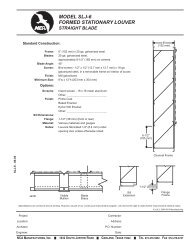
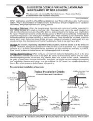
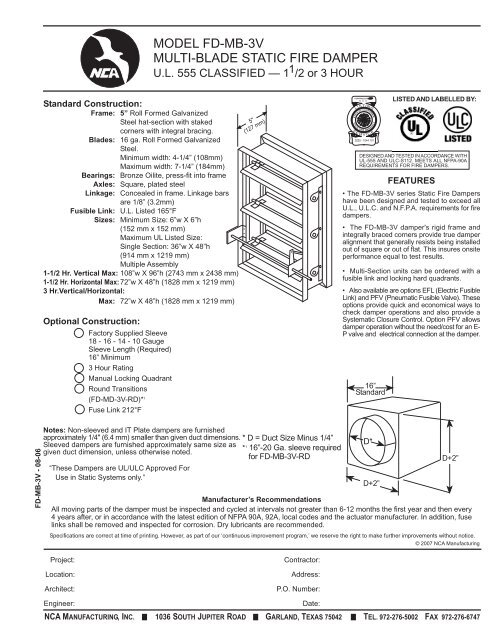
<strong>MODEL</strong> <strong>FD</strong>-<strong>MB</strong>-<strong>3V</strong><strong>MULTI</strong>-<strong>BLADE</strong> <strong>STATIC</strong> <strong>FIRE</strong> <strong>DAMPER</strong>U.L. 555 CLASSIFIED — 1 1 /2 or 3 HOURStandard Construction:Frame: 5” Roll Formed GalvanizedSteel hat-section with stakedcorners with integral bracing.Blades: 16 ga. Roll Formed GalvanizedSteel.Minimum width: 4-1/4” (108mm)Maximum width: 7-1/4” (184mm)Bearings: Bronze Oilite, press-fit into frameAxles: Square, plated steelLinkage: Concealed in frame. Linkage barsare 1/8” (3.2mm)Fusible Link: U.L. Listed 165°FSizes: Minimum Size: 6”w X 6”h(152 mm x 152 mm)Maximum UL Listed Size:Single Section: 36”w X 48”h(914 mm x 1219 mm)Multiple Assembly1-1/2 Hr. Vertical Max: 108”w X 96”h (2743 mm x 2438 mm)1-1/2 Hr. Horizontal Max: 72”w X 48”h (1828 mm x 1219 mm)3 Hr.Vertical/Horizontal:Max: 72”w X 48”h (1828 mm x 1219 mm)Optional Construction:Factory Supplied Sleeve18 - 16 - 14 - 10 GaugeSleeve Length (Required)16” Minimum3 Hour RatingManual Locking QuadrantRound Transitions(<strong>FD</strong>-MD-<strong>3V</strong>-RD)* 1Fuse Link 212°F5"(127 mm)LISTINGSTATE OF CALIFORNIASTATE<strong>FIRE</strong>S E R VM A R S H A L LIC EFEATURES• The <strong>FD</strong>-<strong>MB</strong>-<strong>3V</strong> series Static Fire Dampershave been designed and tested to exceed allU.L., U.L.C. and N.F.P.A. requirements for firedampers.• The <strong>FD</strong>-<strong>MB</strong>-<strong>3V</strong> damper's rigid frame andintegrally braced corners provide true damperalignment that generally resists being installedout of square or out of flat. This insures onsiteperformance equal to test results.• Multi-Section units can be ordered with afusible link and locking hard quadrants.• Also available are options EFL (Electric FusibleLink) and PFV (Pneumatic Fusible Valve). Theseoptions provide quick and economical ways tocheck damper operations and also provide aSystematic Closure Control. Option PFV allowsdamper operation without the need/cost for an E-P valve and electrical connection at the damper.16”StandardLISTED AND LABELLED BY:DESIGNED AND TESTED IN ACCORDANCE WITHUL-555 AND ULC-S112. MEETS ALL NFPA-90AREQUIREMENTS FOR <strong>FIRE</strong> <strong>DAMPER</strong>S.<strong>FD</strong>-<strong>MB</strong>-<strong>3V</strong> - 08-06Notes: Non-sleeved and IT Plate dampers are furnishedapproximately 1/4" (6.4 mm) smaller than given duct dimensions.Sleeved dampers are furnished approximately same size asgiven duct dimension, unless otherwise noted.“These Dampers are UL/ULC Approved ForUse in Static Systems only.”* D = Duct Size Minus 1/4”* 1 16”-20 Ga. sleeve requiredfor <strong>FD</strong>-<strong>MB</strong>-<strong>3V</strong>-RDManufacturer’s RecommendationsAll moving parts of the damper must be inspected and cycled at intervals not greater than 6-12 months the first year and then every4 years after, or in accordance with the latest edition of NFPA 90A, 92A, local codes and the actuator manufacturer. In addition, fuselinks shall be removed and inspected for corrosion. Dry lubricants are recommended.Specifications are correct at time of printing. However, as part of our ‘continuous improvement program,’ we reserve the right to make further improvements without notice.© 2007 <strong>NCA</strong> ManufacturingD*D+2”D+2”Project:Location:Architect:Contractor:Address:P.O. Number:Engineer:<strong>NCA</strong> MANUFACTURING, INC. 1036 SOUTH JUPITER ROAD GARLAND, TEXAS 75042 TEL. 972-276-5002 FAX 972-276-6747Date:
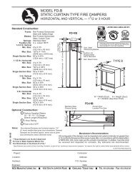
<strong>MODEL</strong> <strong>FD</strong>-<strong>MB</strong>-<strong>3V</strong><strong>MULTI</strong>-<strong>BLADE</strong> <strong>STATIC</strong> <strong>FIRE</strong> <strong>DAMPER</strong>U.L. 555 CLASSIFIED — 1 1 /2 or 3 HOURPERFORMANCE DATA© 2007 <strong>NCA</strong> ManufacturingPressure drop testing was done by an independent laboratory to AMCA Standard 500-D, Fig. 5.3ductwork upstream & downstream.PRESSURE DROP - INCHES OF WATER (In. W.C.)1.0.9.8.7.6.5.4.3.25.2.15.1.09.08.07.06.05.04.03.025.02.015.01<strong>DAMPER</strong> SIZE 36 x 36100 150 200 300 400 500 700 900 1500 2000 3000 4000 60001000VELOCITY THROUGH FACE AREA2.5<strong>DAMPER</strong> SIZE 24 x 242.5<strong>DAMPER</strong> SIZE 12 X 1222<strong>FD</strong>-<strong>MB</strong>-<strong>3V</strong> - 08-06PRESSURE DROP - INCHES OF WATER (In. W.C.)1.51.0.9.8.7.6.5.4.3.25.2.15.1.09.08.07.06.05.04.03.025.02.015PRESSURE DROP - INCHES OF WATER (In. W.C.)1.51.0.9.8.7.6.5.4.3.25.2.15.1.09.08.07.06.05.04.03.025.02.015.01100 150 200 300 400 500 700 900 1500 2000 3000 4000 60001000VELOCITY THROUGH FACE AREA.01100 150 200 300 400 500 700 900 1500 2000 3000 4000 60001000VELOCITY THROUGH FACE AREA<strong>NCA</strong> MANUFACTURING, INC. 1036 SOUTH JUPITER ROAD GARLAND, TEXAS 75042 TEL. 972-276-5002 FAX 972-276-6747