H7ER for pdf - OMRON Russia ПРОМЭНЕРГОАВТОМАТИКА ...
H7ER for pdf - OMRON Russia ПРОМЭНЕРГОАВТОМАТИКА ...
H7ER for pdf - OMRON Russia ПРОМЭНЕРГОАВТОМАТИКА ...

Create successful ePaper yourself
Turn your PDF publications into a flip-book with our unique Google optimized e-Paper software.
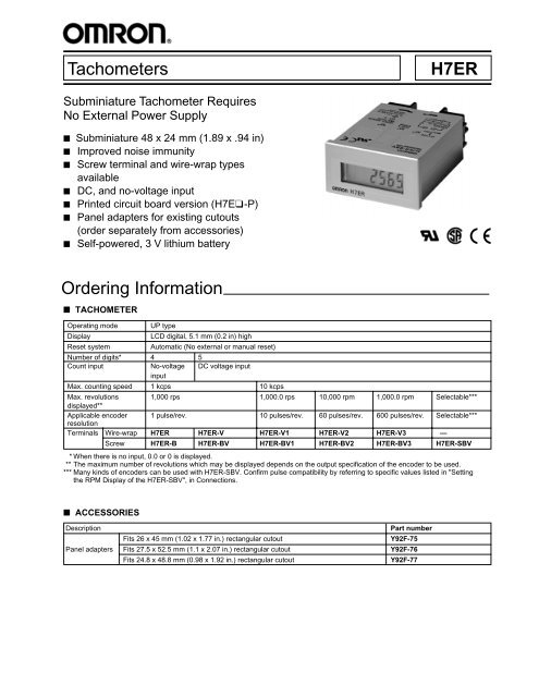
Tachometers <strong>H7ER</strong>Subminiature Tachometer RequiresNo External Power Supply■ Subminiature 48 x 24 mm (1.89 x .94 in)■ Improved noise immunity■ Screw terminal and wire-wrap typesavailable■ DC, and no-voltage input■ Printed circuit board version (H7E❑-P)■ Panel adapters <strong>for</strong> existing cutouts(order separately from accessories)■ Self-powered, 3 V lithium batteryOrdering In<strong>for</strong>mation■ TACHOMETEROperating mode UP typeDisplayLCD digital, 5.1 mm (0.2 in) highReset systemAutomatic (No external or manual reset)Number of digits* 4 5Count input No-voltage DC voltage inputinputMax. counting speed 1 kcps 10 kcpsMax. revolutions 1,000 rps 1,000.0 rps 10,000 rpm 1,000.0 rpm Selectable***displayed**Applicable encoder 1 pulse/rev. 10 pulses/rev. 60 pulses/rev. 600 pulses/rev. Selectable***resolutionTerminals Wire-wrap <strong>H7ER</strong> <strong>H7ER</strong>-V <strong>H7ER</strong>-V1 <strong>H7ER</strong>-V2 <strong>H7ER</strong>-V3 —Screw <strong>H7ER</strong>-B <strong>H7ER</strong>-BV <strong>H7ER</strong>-BV1 <strong>H7ER</strong>-BV2 <strong>H7ER</strong>-BV3 <strong>H7ER</strong>-SBV* When there is no input, 0.0 or 0 is displayed.** The maximum number of revolutions which may be displayed depends on the output specification of the encoder to be used.*** Many kinds of encoders can be used with <strong>H7ER</strong>-SBV. Confirm pulse compatibility by referring to specific values listed in "Settingthe RPM Display of the <strong>H7ER</strong>-SBV", in Connections.■ ACCESSORIESDescriptionPart numberFits 26 x 45 mm (1.02 x 1.77 in.) rectangular cutoutY92F-75Panel adapters Fits 27.5 x 52.5 mm (1.1 x 2.07 in.) rectangular cutout Y92F-76Fits 24.8 x 48.8 mm (0.98 x 1.92 in.) rectangular cutoutY92F-77
<strong>H7ER</strong><strong>H7ER</strong>Specifications■ RATINGSSupply voltageInputMaximum countingspeedReset time<strong>H7ER</strong>-SBV: 5 to 24 VDC ± 10%, Ripple (p-p): 5% max.DC voltage and No-voltage input types: Not required (powered by built-in battery)DC voltage input: 4.5 to 30 VDC at "High" (logic) level0 to 2 VDC at "Low" (logic) levelNo-voltage input:Maximum short-circuit impedance: 10 kΩ max.Short-circuit residual voltage: 0.5 V max.Minimum open impedance: 500 kΩ min.1 kcps (gate time: 1 second)10 kcps (gate time: 1 second)Automatic (no external or manual reset)Approved by the following standardsULCSACE (EMC)■ CHARACTERISTICSInsulation resistanceDielectric strengthVibrationShockAmbient temperatureHumidityBattery lifeWeight100 MΩ min. at 500 VDC1,000 VAC 50/60 Hz <strong>for</strong> 1 minute between current-carrying terminalsand exposed non-current-carrying metal partsMechanical durability: 10 to 55 Hz; 0.75 mm (0.03 in) double amplitudeMalfunction durability: 10 to 55 Hz; 0.3 mm (0.02 in) double amplitudeMechanical durability: Approx. 30 GMalfunction durability: Approx. 10 GOperating: -10° to 55°C (14° to 131°F)Storage: -25° to 65°C (-13° to 149°F)Operating: 35 to 85% RH7 years min. of continuous operation<strong>H7ER</strong>-SBV: approx. 80 g (2.82 oz)DC voltage & No-voltage input types: approx. 60 g (2.12 oz)(including mounting bracket)Timing ChartCount inputMultiply/dividefactorInside gateInside countvalueNumberindicator2
<strong>H7ER</strong><strong>H7ER</strong>DimensionsUnit: mm(inch)■ SCREW TERMINAL TACHOMETERSNo-voltage and DC Input Types48.9(1.93)44.8(1.76)M4 Mounting post8 mm Mounting nutMountingbracket2.51122.2 +0.5-0(0.87 +0.02-0 )Panel cutout45 +0.5-0(1.77 +0.02-0 )2.5M3.5 screw terminal24(0.94)22 (0.87)48 (1.89)430 1333 (1.30)AC/DC Voltage Input Type44.8(1.76)M4 Mounting post8 mm Mounting nutMounting bracket11Panel cutout78.9(3.11)2.522.2 +0.5-0(0.87 +0.02-0 )45 +0.5-0(1.77 +0.02-0 )M3.5 screw terminal24(0.94)22 (0.87)48 (1.89)4 6073 (2.87)13■ WIRE-WRAP TERMINAL TACHOMETERS44.8(1.76)M4 Mounting post8 mm Mounting nutMounting bracketPanel cutout112.522.2 +0.5-0+0.02-0 ) (0.87+0.545 -0+0.02(1.77 -0 )2.5M4 Mountingpost10 (0.39)Mounting holes and footprint5-dia. mountingWire-wrap terminalhole(1 x 1 mm) Four 5-dia. terminalhole22(0.87)24(0.94)5430 2656 (2.20)48 (1.89)18.537 (1.46)3
<strong>H7ER</strong><strong>H7ER</strong>■ PANEL MOUNTING ADAPTERSY92F-75Two 3.5 mm dia. mounting holesPanel cutout2-M331(1.22)24.2 22.22626(1.02)45.248.26372(2.83)44563(2.48)Y92F-764.5 mm dia. mounting holePanel cutout2-M450(1.97)38 24.2 22.238(1.50) 27.545.248.260(2.36)452.5(2.07)Y92F-77Panel cutoutRPM28.8(1.13)24.2 22.224.8(0.98)<strong>H7ER</strong>45.248.253.8 (2.12)448.8(1.92)Connections■ NO-VOLTAGE INPUT TYPESolid-state input (open collector input of an NPN transistor)■ DC VOLTAGE INPUT TYPESolid-state input (open collector input of an NPN transistor)0V<strong>H7ER</strong>Note: Do notconnect or useterminals 3 and4 <strong>for</strong> any reason.+V0V<strong>H7ER</strong>5 to 24 VDCNote: When using <strong>H7ER</strong>-SBV, connect an external power supply as shown bythe dotted line. Other than that, do not connect or use terminals 3 or 4<strong>for</strong> any reason.4
<strong>H7ER</strong><strong>H7ER</strong>■ SETTING THE RPM DISPLAY OF THE<strong>H7ER</strong>-SBVThe model <strong>H7ER</strong>-SBV Tachometer can display the rotatingspeed of different encoders in either revolutions per second orper minute.The tachometer is set by using a sliding selector switch andthree selectors, located under a flip-up cover on the tachometer.Settings and accurately-displayed values depend upon therevolutions output of encoder.To access the switches, press the tachometer cover near thehinged cover.10 2 101 10 0Push to open■ CALCULATING TACHOMETER SETTINGSIf the encoder you plan to use has a resolution not listed in thetable, it will be necessary to calculate the tachometer switchsettings.RPS settingsIf the tachometer is to displayrps, set the DIVIDE/MULTIPLY "÷"switch to DIVIDE. The selectorsettings correspond exactly tothe resolution value of theencoder.For example, if the encoder you plan to use has a resolution of287, and you desire the tachometer to display in units ofrevolutions per second display, set the tachometer switches asfollows:DIVIDE/MULTIPLY switch: DIVIDELeft selector (10 2 ): 2Center selector (10 1 ): 8Right selector (10 0 ): 7(÷)(x)Refer to table below to set tachometer.■ SETTING PROCEDUREThe table below shows the proper tachometer settings <strong>for</strong> themost common encoder resolutions.Unit Encoder Tachometer settings Revolutionsresolution DIVIDE/ B Rmin RmaxA MULTIPLY 10 2 10 1 10 01 DIVIDE 0 0 1 1 10,00010 DIVIDE 0 1 0 1 1,00020 DIVIDE 0 2 0 1 50030 DIVIDE 0 3 0 1 33360 DIVIDE 0 6 0 1 166rps 100 DIVIDE 1 0 0 1 100120 DIVIDE 1 2 0 1 83200 DIVIDE 2 0 0 1 50360 DIVIDE 3 6 0 1 27600 DIVIDE 6 0 0 1 161 MULTIPLY 0 6 0 60 10,00010 MULTIPLY 0 0 6 6 10,00020 MULTIPLY 0 0 3 3 10,00030 MULTIPLY 0 0 2 2 10,00060 DIVIDE 0 0 1 1 10,000120 DIVIDE 0 0 2 1 5,000180 DIVIDE 0 0 3 1 3,333rpm 240 DIVIDE 0 0 4 1 2,500300 DIVIDE 0 0 5 1 2,000360 DIVIDE 0 0 6 1 1,666420 DIVIDE 0 0 7 1 1,428480 DIVIDE 0 0 8 1 1,250540 DIVIDE 0 0 9 1 1,111600 DIVIDE 0 1 0 1 1,000For example, if the encoder you plan to use has a resolution of180, and you desire the tachometer to display revolutions perminute, set the tachometer to display revolutions per minuteusing the following settings:DIVIDE/MULTIPLY switch: DIVIDELeft selector (10 2 ): 0Center selector (10 1 ): 0Right selector (10 0 ): 3In this example, the tachometer display will read accuratelyfrom 1 to 3,333 rpm. Should the encoder input be outside thisrange, the tachometer readout will be inaccurate.RPM settingsFor the tachometer to display rpm, the encoder resolution valuemust be a factor of 60, or divisible evenly into 60, and equal toor greater than 60.When the resolution of theencoder is less than 60, set theDIVIDE/MULTIPLY switch toMULTIPLY.Calculate the selector settings with the following <strong>for</strong>mula:where:B = 60 ÷ AB = value to be set on the selector switchesA = resolution of the encoderFor example, if the encoder has a resolution of 5, the calculationwould be:60 ÷ 5 = 12thus, the tachometer settings would be:DIVIDE/MULTIPLY switch: MULTIPLYLeft selector (10 2 ): 0Center selector (10 1 ): 1Right selector (10 0 ): 2When the resolution of the encoder is equal to, or greater than60, set the DIVIDE/MULTIPLY switch to DIVIDE.Calculate the DIP switch settings with the following <strong>for</strong>mula:B = A ÷ 60For example, if the encoder has a resolution of 720, thecalculation would be:720 ÷ 60 = 12"x"thus, the tachometer settings would be:DIVIDE/MULTIPLY switch: DIVIDELeft selector (10 2 ): 0Center selector (10 1 ): 1Right selector (10 0 ): 25
<strong>H7ER</strong><strong>H7ER</strong>Calculating minimum (Rmin) and maximum (Rmax)revolutionsIn all of the above cases, the number of revolutions theencoder transmits must fall within a calculated minimum andmaximum range. If the encoder's output exceeds or falls belowthis range, the number of revolutions will not be displayedaccurately. Also, the tachometer cannot represent valuesgreater than 10,000, even if the calculated value indicatesotherwise.Installation■ WIRE-WRAP TERMINALSThe terminals used on H7E wire-wrap models have a crosssectional dimension of 1 x 1 mm. Select one of the threegauges of wire from the table at right. Also listed in the tableare the appropriate wiring hardware.Calculating the maximum number of revolutions (Rmax)When displaying in rpm:Rmax = 10,000 x 60/A (rpm) or 10,000 (rpm),whichever is smaller.When displaying in rps,Rmax = 10,000/A (rps)Calculating the minimum number of revolutions (Rmin)With selector switch at DIVIDE positionRmin = 1 (rpm or rps)With selector switch at MULTIPLY positionRmin = 60/A (rpm)Wire gauge Bit Sleeve MethodAWG22 2-A 2-B Normal wire-wrapAWG24 1-A 1-B Normal wire-wrapAWG26 3-A 3-B Normal wire-wrap■ CAUTIONS CONCERNING THE <strong>H7ER</strong> TACHOMETEROn some H7E models, the power input terminal and thecommon signal input terminal (terminals 2 and 4) are internallyshort-circuited. Pay special attention to polarity when wiringthese terminals.Keep the input wiring as short as possible.Whenever possible, avoid routing the input wiring of the AC/DCvoltage input type in parallel with 200 to 240 VAC power lines.If the input wiring must be routed together with the power lines,keep the length of that portion of wire running parallel with thepower lines to within 20 m (65.6 feet).When using shielded wire, stray capacitance may occur. Theoperation of the tachometer might be affected when using wireswhich have a capacitance which exceeds 500 pF (about 10 m,32.8 feet, with parallel wires of 2 mm 2 ). Keep all wires as shortas possible.■ HOW TO MOUNT THE TACHOMETERInsert the <strong>H7ER</strong> tachometer from the front of the mountingpanel. Slide the mounting bracket into place from the rear ofthe panel, and tighten the knurled nut by hand. Do not use tools(such as pliers) to tighten the nut. Excessive tightening maydamage the tachometer. Wire-wrap terminal models may beback-mounted, by soldering the terminals to a printed circuitboard.NOTE: DIMENSIONS SHOWN ARE IN MILLIMETERS. To convert millimeters to inches, divide by 25.4.Omron Europe B.V. EMA-ISD, tel:+31 23 5681390, fax:+31 23 5681397, http://www.eu.omron.com/emaCat. No. GC CN4A 6/98/26M Specifications subject to change without notice. Printed in the U.S.A.6