SM50 Sump Pump Operators Manual - Submarine Manufacturing ...
SM50 Sump Pump Operators Manual - Submarine Manufacturing ...
SM50 Sump Pump Operators Manual - Submarine Manufacturing ...
- No tags were found...

Create successful ePaper yourself
Turn your PDF publications into a flip-book with our unique Google optimized e-Paper software.
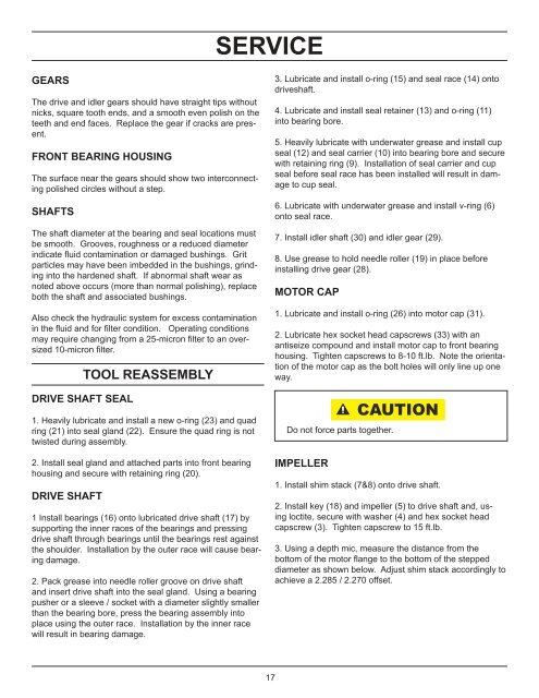
SERVICEGEARSThe drive and idler gears should have straight tips withoutnicks, square tooth ends, and a smooth even polish on theteeth and end faces. Replace the gear if cracks are present.FRONT BEARING HOUSINGThe surface near the gears should show two interconnectingpolished circles without a step.SHAFTSThe shaft diameter at the bearing and seal locations mustbe smooth. Grooves, roughness or a reduced diameterindicate fl uid contamination or damaged bushings. Gritparticles may have been imbedded in the bushings, grindinginto the hardened shaft. If abnormal shaft wear asnoted above occurs (more than normal polishing), replaceboth the shaft and associated bushings.Also check the hydraulic system for excess contaminationin the fl uid and for fi lter condition. Operating conditionsmay require changing from a 25-micron fi lter to an oversized10-micron fi lter.DRIVE SHAFT SEALTOOL REASSEMBLY1. Heavily lubricate and install a new o-ring (23) and quadring (21) into seal gland (22). Ensure the quad ring is nottwisted during assembly.2. Install seal gland and attached parts into front bearinghousing and secure with retaining ring (20).DRIVE SHAFT1 Install bearings (16) onto lubricated drive shaft (17) bysupporting the inner races of the bearings and pressingdrive shaft through bearings until the bearings rest againstthe shoulder. Installation by the outer race will cause bearingdamage.2. Pack grease into needle roller groove on drive shaftand insert drive shaft into the seal gland. Using a bearingpusher or a sleeve / socket with a diameter slightly smallerthan the bearing bore, press the bearing assembly intoplace using the outer race. Installation by the inner racewill result in bearing damage.3. Lubricate and install o-ring (15) and seal race (14) ontodriveshaft.4. Lubricate and install seal retainer (13) and o-ring (11)into bearing bore.5. Heavily lubricate with underwater grease and install cupseal (12) and seal carrier (10) into bearing bore and securewith retaining ring (9). Installation of seal carrier and cupseal before seal race has been installed will result in damageto cup seal.6. Lubricate with underwater grease and install v-ring (6)onto seal race.7. Install idler shaft (30) and idler gear (29).8. Use grease to hold needle roller (19) in place beforeinstalling drive gear (28).MOTOR CAP1. Lubricate and install o-ring (26) into motor cap (31).2. Lubricate hex socket head capscrews (33) with anantiseize compound and install motor cap to front bearinghousing. Tighten capscrews to 8-10 ft.lb. Note the orientationof the motor cap as the bolt holes will only line up oneway.Do not force parts together.IMPELLERCAUTION1. Install shim stack (7&8) onto drive shaft.2. Install key (18) and impeller (5) to drive shaft and, usingloctite, secure with washer (4) and hex socket headcapscrew (3). Tighten capscrew to 15 ft.lb.3. Using a depth mic, measure the distance from thebottom of the motor fl ange to the bottom of the steppeddiameter as shown below. Adjust shim stack accordingly toachieve a 2.285 / 2.270 offset.17