Kirby Morgan EXO-BR Mask Manual - Submarine Manufacturing ...
Kirby Morgan EXO-BR Mask Manual - Submarine Manufacturing ...
Kirby Morgan EXO-BR Mask Manual - Submarine Manufacturing ...

Create successful ePaper yourself
Turn your PDF publications into a flip-book with our unique Google optimized e-Paper software.
<strong>EXO</strong> Full Face <strong>Mask</strong> <strong>Manual</strong>IMPORTANT SAFETY INFORMATIONThis <strong>EXO</strong> Full Face <strong>Mask</strong> is intended for use by trained divers who have successfully completed arecognized training course in the use of a full face mask, and if used in the surface supplied mode, anapproved surface supplied diving course.WARNING: Follow all the instructions in this manual carefully and heed all safetyprecautions. Improper use of this diving mask could result in serious injury or death.DANGER: <strong>Kirby</strong> <strong>Morgan</strong> Dive Systems, Inc. (KMDSI) warns all divers who use the<strong>EXO</strong> Full Face <strong>Mask</strong> to use only KMDSI original spare parts from a KMDSI authorizeddealer. Although other parts, O-rings and fittings may not to be manufactured to thesame standards maintained by KMDSI. The use of any spares other than KMDSI originalparts may lead to equipment failure and accidents.DANGER: Diving in an environment that is chemically, biologically, or radiologicallycontaminated is extremely hazardous. Although the <strong>EXO</strong> Full Face <strong>Mask</strong> may beadapted for use in some contaminated environments, special training, equipment, andprocedures are necessary. Do not dive in a contaminated environment unless you havebeen thoroughly trained and equipped for this type of diving..Read this manual before using or maintaining the mask, even if you have experience with other divingmasks. If you have purchased the mask new from a dealer, be sure to send in the warranty registrationcard so we may keep you informed regarding any safety notices that affect this product. If you resell orloan this mask to another diver, be sure this manual accompanies the mask and that the person reads andunderstands the manual.DANGER: Diving is a life threatening occupation. Even if you do everything rightyou can still be killed or injured. None of the models of <strong>Kirby</strong> <strong>Morgan</strong> Band <strong>Mask</strong> canprevent accidents, injuries or death due to improper training, lack of health, impropersupervision, improper job requirements, improper maintenance or acts of God.WARNING: DO NOT dive this mask in water containing high concentrations ofpetroleum based chemicals. DO NOT use any chemical locking liquids anywhere onthe mask. DO NOT use any type of aerosol sprays on the mask. These chemicals canattack, damage, and compromise the structural integrity of the plastic parts on themask . Clean the mask using only mild soap and water.Document # 050415003 © Copyright 1970-2003 <strong>Kirby</strong> <strong>Morgan</strong> Dive Systems, Inc. All rights reserved.iii
<strong>EXO</strong> Full Face <strong>Mask</strong> <strong>Manual</strong>WARNING: This mask was completely checked and should be ready to dive as itwas shipped from the factory. However, it is always the diver's responsibility to checkall the components of the mask prior to diving.This manual is supplied to the original purchaser of this mask. If you have any questions about the useof the mask or you need another copy of this manual, Part Number 100-030, contact KMDSI. If you haveany questions regarding the use, maintenance, or operation of this mask, contact KMDSI at (805) 928-7772DANGER: The <strong>EXO</strong> Full Face <strong>Mask</strong> is not equipped or lubricated for oxygenservice. Using this mask with oxygen percentages above 50% by volume may lead toexplosions that can result in serious injury or death.KMDSI regards the use of any breathing gas mixture greater than 50% oxygen to be treated as oxygen.This belief is in keeping with the recommendations set forth by the National Fire Protection Association(NFPA), Compressed Gas Association (CGA), and the American Society for Testing and Materials(ASTM).All <strong>Kirby</strong> <strong>Morgan</strong> helmets, masks, and low pressure demand regulators must not be usedwith oxygen mixtures in excess of 50% oxygen by volume without first ensuring all lowpressure (less than 225 psig, 15.5 bar) gas transporting components have been cleaned foroxygen service. Only oxygen compatible lubricants such as Krytox and ChristoLubeshould be used on components requiring lubrication and lubricants should be used sparingly.Never mix different types of oxygen compatible lubricants. Helmets or masks usedprimarily for air diving and occasionally for enriched gas use should be cleaned at morefrequent intervals than helmets used for mixed gas diving only.DANGER: <strong>Kirby</strong> <strong>Morgan</strong> “High Pressure Components” (greater than 225 psig,15.5 bar) must not to be used with pure oxygen, Nitrox, or any breathing gas mixtureswith oxygen content greater than 23.5 % by volume. Using oxygen mixtures inaccess of 23.5 % by volume may lead to a fire or explosion, which could result inserious injury or death.The <strong>Kirby</strong> <strong>Morgan</strong> SuperFlow 1st stage scuba regulator, as well as all <strong>Kirby</strong> <strong>Morgan</strong> divecontrol consoles and high-pressure gas components (greater than 225 psig, 15.5 bar) shouldnot be used with pure oxygen, Nitrox, or any breathing gas containing more than 23.5 %oxygen by volume. The first stage is not intended for use with enriched gas mixtures.Any diving helmet, full face mask, regulator, control console or breathing life support item manufacturedor sold by KMDSI must not be used with breathing gas mixtures in excess of 50% oxygen without firstensuring that all gas transporting components have been cleaned for oxygen service, have oxygencompatible soft goods lubricated with an approved oxygen compatible lubricant such as Krytox orChristo Lube grease.iv© Copyright 1970-2003 <strong>Kirby</strong> <strong>Morgan</strong> Dive Systems, Inc. All rights reserved. Document # 050415003
<strong>EXO</strong> Full Face <strong>Mask</strong> <strong>Manual</strong>Operational specifications and limitations for surface supplied air diving and scuba diving for United States use, anda separate chart for European Union use are presented on Page 4. The information has been separated because ofthe differences imposed or required by certain regulating bodies. Whenever <strong>Kirby</strong> <strong>Morgan</strong> diving equipment is usedin countries that have adopted CE Certification, only CE certified components can be used and all components mustbe part of the tested certified configuration. It is important for the user to understand the rules, regulations, andphilosophy imposed by the governing or regulating bodies whenever diving operations are being planned orconducted. Diving operations must only be conducted within the limits of the operational specifications, and inaccordance with the rules and regulations established by the governing authority in the specific country orgeographical location where the diving operations are being conducted. Technical questions regarding thisequipment should be directed to Dive Lab Inc., of 1415 Moylan Road, Panama City Beach Florida. Telephone 850235-2715, Fax 850-235-0858 e-mail - divelab@aol.comWarranty InformationKMDSI warrants every new mask, helmet, or DCS (Dive Control System) to be freefrom defects in workmanship for a period of ninety (90) days from the date of purchase.This warranty does not cover rubber parts or communications components.Should any part be defective, contact your nearest authorized KMDSI dealer. If thereis no dealer in your area, contact KMDSI directly at (805) 928-7772 or FAX (805)928-0342. You must have a return authorization from KMDSI. Upon approval fromKMDSI, return the defective part, freight prepaid to the KMDSI plant. The part willbe repaired or replaced at no charge as deemed necessary by KMDSI.This warranty becomes null and void if:1) Your completed warranty card is not received by KMDSI within ten (10) daysof purchase date.2) The Warranty Card is not completely filled our or information on thewarranty card is falsified.3) The product has not been properly serviced and maintained according to theappropriate KMDSI manual and the use of <strong>Kirby</strong> <strong>Morgan</strong> Genuine replacement parts.4) Unauthorized modifications have been made to the product.5) The product has been abused or subjected to conditions which are unusual orexceed the product's intended service.Document # 050415003 © Copyright 1970-2003 <strong>Kirby</strong> <strong>Morgan</strong> Dive Systems, Inc. All rights reserved.v
<strong>EXO</strong> Full Face <strong>Mask</strong> <strong>Manual</strong>ContentsA <strong>BR</strong>IEF HISTORY ....................................................................................................................................... 1CHAPTER 1 GENERAL INFORMATION.............................................................................................. 31.1 INTRODUCTION ................................................................................................................................... 31.2 SPECIFICATIONS .................................................................................................................................. 41.2.1 <strong>Mask</strong> Specifications........................................................................................................................... 41.2.2 Operationg Specificatins..................................................................................................................... 61.3 DESIGN PURPOSE ................................................................................................................................ 71.4 ACCESSORIES ...................................................................................................................................... 81.4.1 Hoods ................................................................................................................................................. 81.4.2 <strong>Mask</strong> Carrying Bag............................................................................................................................ 81.4.3 Communications ................................................................................................................................ 81.4.4 Low Pressure High Flow Hose .......................................................................................................... 81.4.5 Manifold Block .................................................................................................................................. 91.4.6 Hose Restrictor .................................................................................................................................. 91.4.7 Regulator Mount Nut Tools ............................................................................................................... 91.4.8 Face Cushion Kit ............................................................................................................................... 91.4.9 Equalizing Device, <strong>EXO</strong> Original only ........................................................................................... 101.4.10 <strong>EXO</strong> Head Protector ........................................................................................................................ 101.4.11 Air Inlet Swivel ............................................................................................................................... 101.4.12 Tool Kit & Pouch ............................................................................................................................ 101.4.13 Over Pressure Relief Valve .............................................................................................................. 10CHAPTER 2 OPERATING INSTRUCTIONS ...................................................................................... 112.1 INTRODUCTION ................................................................................................................................. 112.2 FIRST USE AND PRE-DIVE SET UP ................................................................................................. 112.3 PRE DRESS-IN PROCEDURE ............................................................................................................ 112.4 VISUAL INSPECTION ........................................................................................................................ 112.5 CLEAN FACE PORT ............................................................................................................................ 112.6 ADJUSTING THE EQUALIZER, <strong>EXO</strong> STANDARD OR <strong>BR</strong>............................................................ 122.7 CHECKING REGULATOR FUNCTIONSAND PREPARING THE <strong>EXO</strong> FOR USE IN THE SCUBA MODE. .................................................. 122.8 WIRELESS COMMUNICATIONS ...................................................................................................... 132.9 USING THE <strong>EXO</strong> IN THE SURFACE SUPPLIED MODE ................................................................ 132.10 TESTING THE MANIFOLD BLOCK ................................................................................................. 142.11 DIVER'S HARNESS ............................................................................................................................. 15vi© Copyright 1970-2003 <strong>Kirby</strong> <strong>Morgan</strong> Dive Systems, Inc. All rights reserved. Document # 050415003
<strong>EXO</strong> Full Face <strong>Mask</strong> <strong>Manual</strong>2.12 INSTALLING THE MANIFOLD BLOCK ON THE DIVER'S HARNESS ....................................... 162.13 BAILOUT BOTTLE (AUXILIARY AIR SUPPLY) ............................................................................. 162.14 FIRST STAGE REGULATOR .............................................................................................................. 162.15 OVER PRESSURE RELIEF VALVE ................................................................................................... 172.16 CONNECTING THE HOSES TO THE MANIFOLD BLOCK ........................................................... 172.17 HARD WIRE COMMUNICATIONS ................................................................................................... 182.18 RECOMMENDATIONS FOR DONNING AND REMOVING .......................................................... 182.18.1 Donning ........................................................................................................................................... 192.18.2 Removal .......................................................................................................................................... 192.19 PROPER HOOD FIT ............................................................................................................................ 20CHAPTER 3 IN WATER OPERATIONS ............................................................................................... 213.1 INTRODUCTION ................................................................................................................................. 213.2 WATER ENTRY .................................................................................................................................... 213.3 REGULATOR ADJUSTMENT ............................................................................................................ 213.4 SPIDER ADJUSTMENT ...................................................................................................................... 223.5 PURGING THE MASK ........................................................................................................................ 223.6 LOSS OF <strong>BR</strong>EATHING GAS............................................................................................................... 23CHAPTER 4 POST DIVE PROCEDURES ............................................................................................ 244.1 POST DIVE RINSE .............................................................................................................................. 244.2 REASSEMBLING THE MASK AFTER CLEANING ........................................................................ 24CHAPTER 5 REGULATOR MAINTENANCE..................................................................................... 255.1 GENERAL INFORMATION ................................................................................................................ 255.2 ORIGINAL AND STANDARD <strong>EXO</strong> REGULATOR DISASSEMBLY .............................................. 265.3 ORIGINAL AND STANDARD <strong>EXO</strong> REGULATOR REBUILD ........................................................ 285.4 <strong>EXO</strong> BALANCED REGULATOR DISASSEMBLY ........................................................................... 295.5 <strong>EXO</strong> BALANCED REGULATOR REASSEMBLY ............................................................................ 315.6 REGULATOR ASSEMBLY REMOVAL AND INSTALLATION ....................................................... 335.6.1 Regulator Assembly Removal .......................................................................................................... 335.6.2 Regulator Assembly Installation....................................................................................................... 335.7 <strong>EXO</strong> REGULATOR ADJUSTMENT ................................................................................................... 355.8 LENS REPLACEMENT ....................................................................................................................... 355.8.1 Lens Removal ................................................................................................................................. 35Document # 050415003 © Copyright 1970-2003 <strong>Kirby</strong> <strong>Morgan</strong> Dive Systems, Inc. All rights reserved.vii
<strong>EXO</strong> Full Face <strong>Mask</strong> <strong>Manual</strong>5.8.2 Lens Installation ............................................................................................................................. 365.9 BUCKLE REPLACEMENT ................................................................................................................. 385.9.1 Buckle Removal ............................................................................................................................. 385.9.2 Buckle Installation .......................................................................................................................... 395.10 REPLACING THE FACE SEAL OR FRAME ..................................................................................... 405.10.1 Face Seal Removal ......................................................................................................................... 405.10.2 Face Seal Installation ...................................................................................................................... 415.11 MANIFOLD BLOCK MAINTENANCE ........................................................................................... 415.11.1 Daily ............................................................................................................................................. 415.11.2 Post Dive Procedures .................................................................................................................... 415.11.3 Annual Overhaul ........................................................................................................................... 425.11.3.1 Disassembly ........................................................................................................................... 425.11.3.2 Disassembly & cleaning of the one way valve ...................................................................... 425.11.3.3 Reassembly of the one way valve .......................................................................................... 435.11.3.4 Disassembly of the auxiliary valve ........................................................................................ 435.11.3.5 Cleaning & Lubricating of the auxiliary valve ...................................................................... 445.11.3.6 Reassembly of the auxiliary valve ......................................................................................... 445.11.3.7 Reassembly of the Manifold Block ....................................................................................... 45CHAPTER 6 COMMUNICATIONS ....................................................................................................... 476.1 BARE WIRE BINDING POSTS .......................................................................................................... 476.2 WATERPROOF CONNECTOR (WPC) ...............................................................................................476.3 WIRELESS COMMUNICATIONS ...................................................................................................... 486.4 REMOVING THE COMMUNICATIONS MODULE ......................................................................... 496.5 INSTALLING THE COMMUNICATIONS MODULE ....................................................................... 506.6 EARPHONE AND/OR MICROPHONE REMOVAL .......................................................................... 516.7 EARPHONE AND/OR MICROPHONE INSTALLATION ................................................................. 516.8 REMOVING THE WATERPROOF CONNECTOR (WPC) ................................................................ 516.9 INSTALLING THE WATERPROOF CONNECTOR (WPC) .............................................................. 526.10 REMOVING THE BINDING POSTS .................................................................................................. 526.11 INSTALLING THE BINDING POSTS ................................................................................................ 526.12 WATERPROOF CONNECTOR (WPC) ASSEMBLY REBUILD ....................................................... 536.13 WATERPROOF CONNECTOR (WPC) PIN DIAGRAMS ................................................................. 546.14 POST DIVE MAINTENANCE............................................................................................................. 54EXPLODED VIEWS & PARTS LISTS ......................................................................................................... 56viii© Copyright 1970-2003 <strong>Kirby</strong> <strong>Morgan</strong> Dive Systems, Inc. All rights reserved. Document # 050415003
Chapter 1A <strong>BR</strong>IEF HISTORY<strong>EXO</strong> Full Face <strong>Mask</strong> <strong>Manual</strong><strong>Kirby</strong> <strong>Morgan</strong> Dive Systems, Inc.(KMDSI) is the same corporation (withonly a name change) that startedas the <strong>Kirby</strong> <strong>Morgan</strong> Corporationin 1965. <strong>Kirby</strong> <strong>Morgan</strong>is a registered trademarkfor our products.<strong>Morgan</strong> started designingand making divingequipment shortly after becominga breath-hold diverwhile working as a beach lifeguardin the late 1940s. Therewas very little equipment availablein those early days so it wasnecessary to make much of his owngear.During the early 1950's Bev originatedthe Los Angeles (California) UnderwaterInstructor Program for teaching scubadivers and instructors. A short time laterhe started Dive ‘n Surf, one of the firstdiving equipment suppliers to integratescuba diving instruction into the same operationas sales and service of equipment.Bev, along with his partners Bill and BobMeistrell, designed and manufactured divingequipment whose basis remain as standardsin the diving industry today.In 1957 <strong>Morgan</strong> sold Dive ‘N Surf tohis partners and spent the next two yearscruising the South Pacific aboard a 60 ft.ketch. After returning from the South Pacific,<strong>Morgan</strong> began diving commerciallyas well as designing and making divingequipment for the commercial market.Bev <strong>Morgan</strong>, Chairman of the board, KMDSIThe <strong>Kirby</strong> <strong>Morgan</strong> Corporation wasformed to manufacture commercial divinghelmets. The copper and brass “heavygear” or “Standard Dress” helmets werethe first helmets manufactured by thecompany. Over the years <strong>Kirby</strong> <strong>Morgan</strong>designed, manufactured and sold morethan thirty five diving helmets and thirtyfour diving masks for commercial and militarydivers. Many members of the KMDSIstaff participate as members of the <strong>Kirby</strong><strong>Morgan</strong> design team. It would not be possiblefor us to supply the commercial,military, scientific, and public servicedivers with our <strong>Kirby</strong> <strong>Morgan</strong> DivingEquipment without the team of people thatmake up KMDSI, Inc. (KMDSI).Document # 0504150031
<strong>EXO</strong> Full Face <strong>Mask</strong> <strong>Manual</strong>Chapter 12Document # 050415003
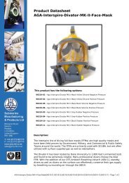
Chapter 1CHAPTER 1GENERAL INFORMATION<strong>EXO</strong> Full Face <strong>Mask</strong> <strong>Manual</strong>1.1 INTRODUCTIONKMDSI has been designing and manufacturingSCUBA, commercial, scientific, search & rescue,and military diving equipment for overthirty years. Many of our products have becomethe standard of the industry due to their design,high quality, and outstanding service. The <strong>EXO</strong>-26 and the <strong>EXO</strong>-<strong>BR</strong> are part of this continuingtradition.The following is a list of features to be foundon the <strong>EXO</strong>-26 Original, <strong>EXO</strong> Standard andthe <strong>EXO</strong>-<strong>BR</strong> Full Face <strong>Mask</strong>s :1) Fully adjustable Regulator:The regulator is fully adjustable over a widerange of operating pressures. By simply turningthe Adjustment Knob while diving, you can"tune" your regulator for your type of diving.2) <strong>EXO</strong>thermic Exhaust system:The regulator assembly in the <strong>EXO</strong> isolates theintake and exhaust chambers from one another.The diver’s own breath assists in reducing thermaldrain by warming certain areas of the regulator.This helps to eliminate freeze ups in coldwater diving.3) Earphone Pockets:The earphones are allowed to equalize becauseall interior parts of the mask share a commoncavity. There is never a need to adjust theirposition and they are easily accessible.4) <strong>EXO</strong>skeleton:The outer frame, or <strong>EXO</strong>skeleton, serves severalfunctions. It protects the face seal and isused to mount external components such as theregulator, lens, and communications.bucklespidermask lensTEMPEREDmask framecommunications moduleregulator adjustment knobDIVING SYSTEMS INTN'LSANTA BARBARA CA./U.S.A.purge buttonFront view of the <strong>EXO</strong> Full Face <strong>Mask</strong>.regulator exhaustDocument # 0504150033
<strong>EXO</strong> Full Face <strong>Mask</strong> <strong>Manual</strong>Chapter 15) Suspension Face Seal:The suspension area of the face seal is attachedto the <strong>EXO</strong>skeleton by five mounting legs,much like a trampoline. In this way, the faceseals on a soft flexible area rather than a narrowand harder type of seal. This allows the <strong>EXO</strong>-26to fit different sizes and shapes of faces. Theextra area behind the face seal allows a foampad to be inserted for extra small (narrow) faces.6) Modular Communications:Microphone and earphones can be easily andquickly replaced. Simply remove the mountingnut and push the entire module to the inside ofthe mask. The earphones and microphone canthen be removed. A spare comm set comes inhandy for rapid replacement in the field ifneeded. If the mask is to be used without communications,an oral nasal plug, KMDSI part #320-001, is available to seal the microphonecup in the oral nasal of the <strong>EXO</strong> Standard or <strong>BR</strong>.7) Oral Nasal:The oral nasal on the <strong>EXO</strong> Standard and the<strong>EXO</strong> <strong>BR</strong> full face mask, helps improve breathingqualities of the demand regulator and alsoimproves the speech intelligibility of certaincommunications devices available for the mask.It is shipped from the factory with the microphonehole punched. All no comm units areshipped with a plastic oral nasal microphonecup plug.This plug should be used when communicationsare not installed.8) Equalizer:An ear equalizing device (nose block device)is a standard feature on both <strong>EXO</strong> Standard and<strong>BR</strong> masks and is used to equalize the diversears. This device has adjustable heights, fittinga variety of noses and faces.9) Balanced Regulator, <strong>EXO</strong> <strong>BR</strong> onlyThe <strong>EXO</strong> is also available with a balanced regulatorwhich has adjustment for a wide range ofoperating pressures. The <strong>EXO</strong> Balanced Regulatorhas been CE approved in Europe for scubause in conjunction with the KMDSI First StageRegulator and Overpressure Relief Valve.410) Automatic Defogging, <strong>EXO</strong> Original only:As the diver inhales, incoming air goes up throughthe inlet tube and down across the lens, defoggingand ventilating the mask with each breath.11) Scuba style ear equalizing<strong>EXO</strong> Original only:A large nose pocket in the mask, allows diversto equalize their ears by pushing back on thenose pocket and pinching. Extra room is providedin the pocket to allow a nose block kit tobe fitted if needed.(see Section 1.4.9)1.2 SPECIFICATIONS1.2.1 <strong>Mask</strong> SpecificationsWeight: 4.65 PoundsConstruction:-Exoskeleton / Poly Carbonate, Lexan ®-Face Seal / Neoprene Blend-Regulator Body / Noryl®-Hardware / Stainless Steel & ChromedBrass-O-Rings / Neoprene-Spider / NeopreneRecommended Lubricant: Silicone Grease,Dow Corning 1111.2.2 Operating SpecificationsThe CE approved <strong>EXO</strong>–26-<strong>BR</strong> complys withEM 250 (edition may 1993). The <strong>EXO</strong>–26-<strong>BR</strong>has been CE tested for scuba use with the KMDSISuperFlow first stage regulator. The <strong>EXO</strong>-26-<strong>BR</strong> has also been CE tested for surface suppliedumbilical diving. Regardless of the mode beingemployed, all components used with, or in conjunctionwith the <strong>EXO</strong> must be CE approved.Whenever <strong>Kirby</strong> <strong>Morgan</strong> diving equipment isused in countries that have adopted CE Certification,only CE certified components can beused and all components must be part of thetested certified configuration. It is important forthe user to understand the rules, regulations, andphilosophy imposed by the governing or regu-Document # 050415003
Chapter 1<strong>EXO</strong> Full Face <strong>Mask</strong> <strong>Manual</strong>lating bodies whenever diving operations arebeing planned or conducted. Diving operationsmust only be conducted within the limits of theoperational specifications, and in accordancewith the rules and regulations established by thegoverning authority in the specific country orgeographical location where the diving operationsare being conducted. Technical questionsregarding this equipment should be directed toDive Lab Inc., of 1415 Moylan Road, PanamaCity Beach Florida. Telephone 850 235-2715,Fax 850-235-0858 e-mail - divelab@aol.comAir Supply Pressure:All <strong>Kirby</strong> <strong>Morgan</strong> masks and helmets are designedfor a maximum working supply pressureof 225 psig (15.5 bar). What this actually meansis the gas train components i.e., intermediatesupply hose, demand regulator and manifoldassemblies are designed to operate at gas supplypressures of up to 225 psig (15.5 bar) above thesurrounding ambient pressure. The regulatoradjustment knob is capable of holding back thispressure, with a little bias in reserve. This is sothe professional working diver can adapt thehelmet or mask to various types of supply systemsfound on dive stations throughout the world.It is not the intention that the mask or the helmetbe normally operated at the high end pressure225 psig. The normal maximum supply pressureto the <strong>EXO</strong>-26 <strong>BR</strong> should be dictated by thedepth and selected in accordance with the specificationlists on page6 for the mode of divingbeing employed. Diving with the gas supplypressure higher than the pressure recommendedfor that depth, can sometimes cause the regulatorto be over active resulting in inlet valve pulsation.The specifications on page 6 are split intotwo charts for surface supplied mode and twocharts for scuba mode in order to conform toEuropean conformance requirements and to allowuse in other countries where standardsdiffer. CE (Conformance Europe) is the standardby which man worn diving equipment istested in the Eurpean union. EN-250 was writtento cover recreational diving equipment and isDocument # 050415003currently being applied to commercial surfacesupplied diving equipment until a standard forthis equipment can be written. The EN-250Standard does not make exception for the differencesbetween recreational and commercial divingequipment and practices. EN-250 does notallow the demand regulator to be adjustable by adiver to a point where a continuous free flow ofgas can be present. Therefore, in order to satisfythe requirements of EN-250 a separate specificationschart was developed (European CE OperationalSpecifications Limitations). When divingscuba with the <strong>EXO</strong> mask, the diver shouldhave an intermediate supply pressure from theSuperFlow first stage at between 135-145 overbottom. This pressure range is more than adequateto supply the work of breathing requirementsof EN-250 with the demand regulatoradjustment knob adjusted for minimal inhalationeffort. Once adjusted in the water, readjustmentneed only be accomplished should thedivers attitude or the current conditions change.The diver should always have the regulatoradjusted for the least inhalation effort based onthe diving conditions, i.e., current or physicalattitude.When diving in the surface supplied mode, thedemand regulator adjustment knob should bechecked periodically during the dive to ensurethe diver is maximizing breathing performancebased on the delivery pressure. The regulatoradjustment knob also serves another very importantfunction, in the unlikely event the maskshould develop a continuous leak of water, thebias adjustment knob can be rotated counterclockwiseallowing a slight free flow to developkeeping the mask clear while the diver aborts thedive. This important feature allows the divershands to be free during the accent. This featureis incorporated in all <strong>Kirby</strong> <strong>Morgan</strong> helmets andfull-face masks designed for commercial use.It is important to understand that the regulatoradjustment device is not intended to be a min./max. device, but simply an adjustment that increasesor decreases spring bias pressure on the5
<strong>EXO</strong> Full Face <strong>Mask</strong> <strong>Manual</strong>Chapter 1inlet valve. The required over bottom pressureshould be applied according to the dive depth.When diving surface supplied the dive shouldstart with the console supply pressure set between115-135 psig (8-9.3 bar). If the diveproceeds deeper than 100 fsw (30 msw) the overbottom pressure should adjusted on the supplyconsole to be between 135-175 psig ( 9.3 – 12bar) over the bottom pressure (ob) according tothe supply specifications on page 6. When surfacesupplied air diving to the extreme air limitsof 175 –220 fsw, a supply pressure of between175 - 200 psig ob (12-14 bar) should be used.During ascent, the console supply pressure shouldbe reduced corresponding to the decrease indepth. Failure to track the pressure, and back offon the supply pressure during ascent could resultin the demand regulator free flow.Note: Best breathing performance is realizedwhen the supply pressure is tracked for depth.U.S Operational Specifications and Limitations:Surface Supply Mode- Maximum depth on air –220 fsw (67 msw)For current Surface Supply Specifications- Maximum depth Refer surface to Addendum: supplied HeO2 – 300fsw (90 msw)- Work rate Operational - Extreme Specifications75 lpm / rmvand Limitations- Umbilical minimum I.D. 3/8” (9.5mm) of onecontinuous length not to exceed (no splices)600’ (182 m)- Required over bottom supply pressure0 -100 fsw (0-30 msw) 115-135 psig ob (8-9.3bar)- 100 -175 fsw (135-175 psig ob (9.3-12 bar)- 175 – 220 fsw (53 - 66 msw) 175-200 psig ob(12 – 14 bar)- Air/gas supply capable of delivering 4.5 acfm(127.4 bl/min to the manifold block)6European CE Operational Specifications andLimitations : Surface Supplied Mode- Maximum depth on air – 50 msw (164 fsw)- Umbilical minimum I.D. 3/8” (9.5mm) of onecontinuous length (no splice) not to exceed 100m(328 ft)- Work rate - Heavy 62.5 lpm / rmv- Required over bottom pressure 0 – 30 msw(0 -100 fsw) 8 – 9.3 bar (115 – 135 psig)30 – 50 msw (100 – 164 fsw) 9.3 – 12 bar(135-175 psig)- Air/gas supply capable of delivering 4.5 acfm(127.4 bl/min) to the manifold blockU.S. Operational Specifications SCUBA ModeEquipped with KMDSI SuperFlow 1st Stage- maximum depth tested 198 fsw (60 msw)- Maximum depth – 190 fsw ( 57 msw)(KMDSI strongly recommends 130 fsw as the maximumdepth for recreational and all scuba diving)- Minimum Intermediate over bottom supplypressure 135 psig (9.3 bar)- Maximum intermediate over bottom supplypressure 175 psig (11.4 bar) (SF 1 st stage maximumshim pressure 155 PSIG)- Work rate - Extreme – 75 lpm / rmvEuropean CE Operational SpecificationsScuba Mode- First stage CE approved KMDSI SuperFlowonly- Maximum depth air – 50 msw (164 fsw)(KMDSI strongly recommends 39 msw (130 fsw)as the maximum depth for scuba diving)- Maximum depth tested to on air 50 msw (164fsw)Document # 050415003
Chapter 1<strong>EXO</strong> Full Face <strong>Mask</strong> <strong>Manual</strong>- Minimum Intermediate over bottom supplypressure 135 psig (9.3 bar)- Maximum intermediate over bottom supplypressure 165 psig (11.4 bar) (SF 1 st stage maximumshim pressure 155 psig)- Work rate - Heavy – 62.5 lpm / rmv1.3 DESIGN PURPOSEAll the <strong>EXO</strong> Full Face masks have been designedto be used with either SCUBA gear oras part of a surface supplied diving system. Allmodels work exceptionally well in subfreezingconditions and allow the use of a wide range ofsupply pressures, giving the user greater flexibilityin adapting to various surface supportedsystems. These masks are compatible with mostcommercially available wire type and throughwater communications, making them ideal forcommercial, scientific and search/rescue diving.The <strong>EXO</strong> line has become very popularwith many search and rescue teams diving inwater requiring the added safety and protectionof a full face mask.<strong>EXO</strong> Original:The original <strong>EXO</strong> Full Face <strong>Mask</strong> has been inproduction for many years. The simple, ruggeddesign has proven very reliable with a minimumof maintenance. The Original <strong>EXO</strong> utilizesan inlet tube that directs the incoming gasacross the lens, defogging and ventilating themask with each breath. This full face mask bestsuits the daily working diver that routinelyworks at depths down to 130 FSW in extremelyharsh environmental conditions with minimalpre and post dive maintenance.Document # 050415003<strong>EXO</strong> Standard:The <strong>EXO</strong> Standard shares many of the featuresand components found in the Original <strong>EXO</strong>.The demand regulator body has been changedto allow the use of an oral nasal mask in place ofthe inlet tube. The oral nasal mask slightlyimproves the breathing performance and speechintelligibility of various communications systems.All internal regulator hardware and softgoods are interchangeable with the <strong>EXO</strong> Original.Like the Original <strong>EXO</strong>, this mask best suitsthe daily working diver that routinely works atdepths down to 130 FSW in extremely harshenvironmental conditions with minimal pre andpost dive maintenance.WARNING: Do not dive this maskin water containing high concentrationsof petroleum based chemicals. Clean themask using only mild soap and water.<strong>EXO</strong> Balanced Regulator:The <strong>EXO</strong> Balanced Regulator is designed fordeep air diving requiring the highest level ofperformance. Tested by the US Navy for scubaand surface supplied air diving to 190 FSW. Itslow cracking pressure and high flow capabilityallow it to sustain a level of performance onlypreviously achieved by sophisticated and expensivecommercial helmets.This full face mask is best suited for the technical/commercialdiver that is capable of performingthe required routine maintenance. Maintenanceof this mask is required more frequentlythan with the other <strong>EXO</strong> models, but can beaccomplished economically and in less than 15minutes using standard <strong>EXO</strong> adjustment toolsand procedures.WARNING: Contaminated waterdiving operations are extremely hazardous.They should NOT be attempted unlessall members of the dive team havebeen trained for this type of diving. Youmust check to ensure that every pieceof the diver’s equipment is compatiblewith the contamination to be encountered.If there is the slightest doubt regardingwhat contaminants are in thewater, the diver must NOT dive.7
<strong>EXO</strong> Full Face <strong>Mask</strong> <strong>Manual</strong>Chapter 11.4 ACCESSORIESThere are a number of accessories for your <strong>EXO</strong> Full Face <strong>Mask</strong> designed to make your diving moreenjoyable and easier. Contact your nearest Authorized KMDSI dealer to order any of the following items.1.4.1 HoodsKMDSI manufacturers a hood perfectly tailoredto the <strong>EXO</strong>-26 masks. It has thinner face sealmaterial on the front as opposed to the thickermaterial of normal types of hoods, for bettercomfort. Order Part #: 310-030 Small, 310-031Medium, 310-032 Large.Cold Water (CW) versions are also available.These have a large "bib" that tucks into the diverswet suit. Order Part #: 310-035 CW Small, 310-037 CW Medium, 310-039 CW Large1.4.3 CommunicationsThe mask may be used with wireless or hardwire communications. Several different typesof communications modules can be ordered forthe <strong>EXO</strong>. For the cleanest communications, werecommend you use only KMDSI replacementcommunications earphones and microphones.<strong>EXO</strong> OriginalPart #: Description315-201 Asembly With Binding Posts315-206 With 4 Pin Waterproof Connector<strong>EXO</strong> Standard and <strong>BR</strong>Three sizes of hoods are available1.4.2 <strong>Mask</strong> Carrying BagPart #: Descript315-210 Assembly With Binding Posts315-215 With 4 Pin Waterproof Connector1.4.4 Low Pressure High Flow HoseTo protect your mask during storage and transport,use our <strong>Mask</strong> Carrying Bag. The bag holdsyour mask as well as spares. The bag is notintended for shipping your mask as cargo. OrderPart #: 300-902, <strong>Mask</strong> Carrying Bag..A low pressure high flow hose for the <strong>EXO</strong>-26or <strong>EXO</strong>-<strong>BR</strong> is available. This hose will deliverthe maximum amount of air to the regulator.Order Part #: 255-050, LP High Flow Hose.8Document # 050415003
Chapter 1<strong>EXO</strong> Full Face <strong>Mask</strong> <strong>Manual</strong>CAUTION: If the <strong>EXO</strong> is used in thesurface supplied mode the diver must beequipped with a proper bailout systemand one way valve. See Chapter 2 of thismanual for a detailed list of the items tobe included in the bailout system.1.4.5 Manifold BlockIf you use the <strong>EXO</strong> for surfacesupplied diving, amanifold block which has aone way valve and providesfor correct attachment of theumbilical is essential. The auxiliaryvalve on the manifold block also controlsthe flow of the bailout supply.Order Part #:300-145 9/16" SCUBA fitting on one way valve300-150 9/16" oxygen fitting on one way valve300-155 #6 JIC fitting on one way valve1.4.6 Hose Restrictor1.4.8 Face Cushion KitA face cushion kit for the <strong>EXO</strong>-26 and <strong>EXO</strong>-<strong>BR</strong> is available. While the majority of ownersfind the mask provides a watertight seal rightout of the box, some divers with small or narrowfaces may experience trouble getting a comfortable,tight seal. This optional cushion is designedto give divers with smaller faces a betterseal. It is easily installed to the interior of themask. Two velcro tabs secure the cushion insidethe seal, with the ends of the cushion slippedinto the earphone pockets.Order Part #: 325-025, Face Cushion KitThe <strong>EXO</strong> Face Cushion KitThe manifold block has extra portsthat allow for attachment of a drysuit inflator hose. Most dry suit inflationhoses have a built in flow restrictor thatlimits the gas flow to the dry suit inflation valveif the hose gets severed. It also allows a finercontrol of the gas entering the suit. If the hosebeing used is not restricted, the KMDSI flowrestrictor Part # 555-210 must be used.Caution: Never attach or use a dry suit inflationhose that is not restricted or does dothave the KMDSI restrictor in place.These tools are used for removing and replacing the regulator assembly. The mount nut toolworks on the newer <strong>EXO</strong>-Standard and <strong>EXO</strong>-<strong>BR</strong> as well as the <strong>EXO</strong>-26's with the original styleregulator mount nuts. These tools are required if an entire regulator rebuild or face seal replacementis to be attempted. These two procedures, entire regulator rebuild and face seal replacement,can be difficult. KMDSI recommends that these two procedures be done by a factorytrained KMDSI dealer. If you are unsure if your local dealer is qualified to do this repair,call KMDSI for the nearest qualified dealer in your area.Order Part #: 325-650 Deluxe Tool Kit9Document # 050415003325-650 Deluxe Tool Kit1.4.7 Regulator Mount Nut Tools
<strong>EXO</strong> Full Face <strong>Mask</strong> <strong>Manual</strong>Chapter 11.4.9 Equalizing Device, <strong>EXO</strong> Original onlyIf you are using heavy mitts it may bedifficult to grasp your nose for clearingon the <strong>EXO</strong> Original.To help eliminate this difficulty,KMDSI offers a special nose clearing devicePart# 325-635.1.4.10 <strong>EXO</strong> Hard ShellThis hhard shell, Part # 300-010, mounts easilyon all models of the<strong>EXO</strong> <strong>Mask</strong>. Thereare reinforced areasfor mounting lightsor small video cameras.1.4.11 Air InletSwivelPart # 305-017,is supplied on allOriginal andStandard <strong>EXO</strong>s. It allowsthe regulator hoseto move freely and alignwith the mask inletwithout putting a stress on the hose coupling. Ituses standard SCUBA threads for incomingbreathing air. It may also be used on secondstage scuba regulators and the <strong>EXO</strong>-<strong>BR</strong>.1.4.13 Overpressure Relief ValveThe KMDSI Overpressure Relief Valve, Part #200-017 is factory adjusted to vent any time thepressure in the low pressure hose connectingthe bailout bottle to your auxiliary valve exceeds200 P.S.I. It is installed in any of the lowpressure ports in the first stage regulator.WARNING: Be sure the bailoutregulator is fitted with a relief valve forover-pressurization of the supply hose.A leaky first stage can overpressure thehose, bursting it. This would cause aloss of the entire bailout supply andpossible physical injury to the diver asthe hose whips about. Do not use a highpressure hose, as the system on themask is not designed for high pressure.The KMDSI Overpressure relief valve hasbeen manufactured in two different flow rates.The original valve had a lower flow rate that thecurrent valve. The current valve has beenmarked in two ways, the first being a groovearound the flats of the hex. Currently the valveis marked with a groove around the top of thebody. These are the same valve, just differentmarking methods.Old 200-015GrooveNew 200-0171.4.12 Tool Kit & PouchA special tool kit and pouch are available to store the back up wrench andregulator adjustment tool.Order Part #: 325-630, Tool Kit & Pouch10325-630Tool Kit& PouchDocument # 050415003
Chapter 2CHAPTER 2OPERATING INSTRUCTIONS<strong>EXO</strong> Full Face <strong>Mask</strong> <strong>Manual</strong>2.1 INTRODUCTIONThis section provides the manufacturer’s recommendationson how to use the three <strong>EXO</strong> FullFace <strong>Mask</strong>s. The use of these diving masks willvary with the type of diving and environmentalconditions. A proper training program in the useof full faced masks must be undertaken prior todiving the mask. Practice using the mask in acalm, clear body of water (pool) before openwater diving. There is a video available fromTeam Visions that goes over many of these basicprocedures. The video, Diving With The <strong>EXO</strong>-26 Full Face <strong>Mask</strong> is available from Best PublishingPO Box 30100 Flagstaff Ariz. 86004Ph 800 468-1055.2.2 FIRST USE AND PRE-DIVE SET UP2.4 VISUAL INSPECTIONVisually inspect the entire exterior and interiorof the mask.- The face seal should be in good condition withno cracks, tears, or punctures.- The spider (head harness) should be intact.Stretch the spider and inspect it carefully forsigns of cracking or tearing.- Inspect the face port. It should be clean andclear. Anti fog solutions should be applied priorto use.-Check the wiring for the communications, ifpresent. Make sure the communication modulemount nut is screwed down tight.When you first receive your <strong>EXO</strong> Full Face<strong>Mask</strong>, carefully unpack it and examine it for anydamage that may have occurred during shipment.Use the inspection sheet provided to ensurethat no damage has occurred! Read allwarning labels & caution tags.Be sure to complete the enclosed warranty cardand return to KMDSI as soon as possible. Warrantyclaims require that a card be on file atKMDSI 10 days after purchase. Incompletewarranty cards are considered invalid.2.3 PRE DRESS-IN PROCEDUREBefore dressing in for a dive, an inspection of themask and all related gear should be made toinsure everything is in proper working order.This should be done well in advance of the dive,so any problems or adjustments can be dealtwith. Read and understand this manual beforeyou dive. Chapter 2 tells you the basic operatingprocedures and how to perform the pre-divemask inspections and pre-dive regulator functiontests.Document # 050415003 © Copyright 1970-2003 <strong>Kirby</strong> <strong>Morgan</strong> Dive Systems, Inc. All rights reserved.-In the <strong>EXO</strong> Original, inspect the air inlet tubeand make sure it is properly seated on the regulator.-In the <strong>EXO</strong> Standard or <strong>BR</strong>, inspect the oralnasal and equalizer and make sure they aresecurely mounted. If the mask does not havecommunications installed, be sure to use a microphonehole plug (320-001) in the oral nasal.-Check the regulator assembly to ensure that it issecured tightly on the mask frame.-Check the regulator cover to ensure that it istight on the regulator body.-With no air to the mask, screw the regulatoradjustment knob all the way out and back in toinsure that it turns freely.2.5 CLEAN FACE PORTRemove any sand or debris from the interior ofthe mask and face port which may be inhaledor blown into the divers face, interfering withthe divers vision.11
<strong>EXO</strong> Full Face <strong>Mask</strong> <strong>Manual</strong>Chapter 2Under certain conditions, depending upon watertemperature, you may find it necessary to prepthe mask lens to keep it from fogging whilediving. There are a number of commercial defoggersavailable for scuba diving which workwell. Follow the directions on the label for use.If no commercial preparation is available it ispossible to use soap. Use a small amount ofliquid soap on a rag and smear a thin film on theinside of the lens. Do not rinse this film off.Apply the soap just prior to entering the water.2.6 ADJUSTING THE EQUALIZER<strong>EXO</strong> STANDARD OR <strong>BR</strong>There are three different height positions thatthe Equalizer can be adjusted to. Carefully peelthe Equalizer out of the Wire Retainer and repositionit in another one of the molded groovesin the Equalizer. The Wire Retainer can also beslightly bent in one direction or another, up ordown, to get the angle of the Equalizer just right.Insure that the corners of the Equalizer groovesare "snapped" into position on the Wire Retainerso that it does not come loose.2.7 CHECKING REGULATOR FUNC-TIONS AND PREPARING THE <strong>EXO</strong>FOR USE IN THE SCUBA MODE.Attach the low pressure hose that is suppliedwith the mask to the low pressure (L.P.) port onyour 1st stage regulator and then to the mask.Never connect the hose or mask to a high pressure(H.P.) port. When attaching the hose to theregulator ALWAYS USE A BACK UPWRENCH ON THE NIPPLE TUBE.CAUTION: If you are not using theinlet angle fitting, a backup wrench mustbe used on the hex fitting of the regulatorwhen tightening. Otherwise the regulatormay come out of adjustment!12Always use a back-up wrench when attaching orremoving a hose to the regulator.Prior to attaching your first stage regulator toyour tank be sure the regulator adjustment knobon the mask is screwed all the way in. This willprevent the regulator from free flowing when theair is turned on.Your 1st stage regulator should be equippedwith a submersible pressure gauge. Attach thefirst stage to your tank and turn the air on whileholding the submersible pressure gauge awayfrom you. Once the air is on, check the pressuregauge to ensure you have a full tank.WARNING: A submersible pressuregauge is considered essential for fullface mask scuba diving. The diver mustplan his dive to avoid running out of airwhile wearing a full face mask. There isno way to safely buddy breathe underwater,use an octopus rig, or snorkel onthe surface while wearing a full facemask. If the submersible pressure gaugeshould fail during the course of a dive,the dive should be terminated immediately.Check the mask regulator for adjustment andfunction. <strong>EXO</strong> masks are preset at KMDSI withan intermediate pressure of 135-145 psi. Startingwith the regulator adjustment knob screwedall the way in, back the regulator adjustmentknob out 3 full turns. There should be no indica-© Copyright 1970-2003 <strong>Kirby</strong> <strong>Morgan</strong> Dive Systems, Inc. All rights reserved. Document # 050415003
Chapter 2<strong>EXO</strong> Full Face <strong>Mask</strong> <strong>Manual</strong>Once you enter the water, the regulator can beadjusted for a variety of diving conditions andpositions just by turning the adjustment knob inor out.2.8 WIRELESS COMMUNICATIONSThere are several manufacturers that produce awireless communications unit that can be usedwith the <strong>EXO</strong> <strong>Mask</strong>. If you are using wirelesscommunications read and follow all manufacturersinstructions for your particular unit.Always check the regulator adjustment for properfunction before you enter the water.tion of air flow through the mask if the intermediatepressure on your first stage regulator is setat around 135-145 psi. Higher first stage regulatorpressures may cause free flow, but turningthe regulator adjustment knob in should stop theflow. In the unlikely event there is still flow,proceed to the regulator adjustment section inChapter 5 to reset the regulator.Loosen all the straps on the Spider and hold themask on your face. Take a couple of goodbreaths, breathing slow and soft at first then hardand fast. The regulator should be operating withthe minimal amount of breathing resistance andno free flowing. Any type of an air flow "hiss"should be able to be adjusted out by using theadjustment knob. If the adjustment knob is adjustedall the way in and the regulator still hisses,see the regulator adjustment section, chapter 5.Pressing the purge button should cause a fairlystrong air flow into the mask. If there is no flowwhen pressing the purge button, or if breathingis difficult, see the regulator adjustment sectionin chapter 5.If you are using wireless communications youshould test the communications by placing thetransducers from both send and receive units ina bucket of water and speaking into the mask.Communications should always be tested priorto the diver entering the water.WARNING: The waterproof casefor your wireless communications unitshould only be attached to your scubabackpack, NEVER to your weight belt. Inthe event your belt must be dropped thebelt must have a clear drop path andmust not be connected to any other pieceof gear. If this procedure is not followedthe weight belt and wireless electronicscase will be attached to the mask by theconnecting wire.2.9 USING THE <strong>EXO</strong> IN THE SURFACESUPPLIED MODEIf you have not been trained in the proper use ofsurface supplied diving equipment we stronglyrecommend that you complete a training coursein the use of this equipment prior to diving surfacesupplied.Read and understand the Checking RegulatorFunction and Preparing The <strong>EXO</strong> for use inscuba mode section of this chapter. The basicconnecting instructions of the mask and regulatorfunction tests are the same.Document # 050415003 © Copyright 1970-2003 <strong>Kirby</strong> <strong>Morgan</strong> Dive Systems, Inc. All rights reserved.13
<strong>EXO</strong> Full Face <strong>Mask</strong> <strong>Manual</strong>Chapter 2WARNING: The <strong>EXO</strong> <strong>Mask</strong> is notequipped with a one way valve (non-returnvalve) as supplied from the factory.For safe surface supplied diving, thediver must use a manifold blockequipped with a one way valve. DO NOTCONNECT THE DIVER'S UMBILICAL DI-RECTLY TO THE <strong>EXO</strong> WITHOUT A ONEWAY VALVE.5) Bailout System: Consisting of a harness, bailout bottle, first stage regulator with over pressurerelief valve. This system connects to theauxiliary valve on the divers manifold block assemblyby a hose.6) Communications System: Provides hardwire communication between diver and top side.The one way valve is a very important component.It prevents the flow of air out of the maskin the event of a sudden lowering of pressure inthe umbilical supply hose due to an accidentalbreak in the hose or fitting. Not only would theauxiliary air be lost if the one way valve failed(concurrent with a hose or fitting break) but thediver could be “squeezed”, a very serious accident.DO NOT DIVE SURFACE SUPPLIEDWITHOUT A ONE WAY VALVE!At a minimum, if the <strong>EXO</strong> is to be used for surfacesupplied diving the following systems andcomponents must be in place and in proper workingcondition.1) Air Supply: Either a low pressure compressoror high pressure air bottles.(see operatingspecifications, pg 4)2) Dive Control System: An air managementbox to control the flow of air delivered to thediver or divers (like the DCS 2A or DCS 3 offeredby KMDSI).The EX0-26 is part of a complete surfacesupplied diving system.2.10 TESTING THE MANIFOLD BLOCK3) Divers Umbilical: Hose bundle consistingof air supply hose, pneumofathometer hose(depth sensing), communications wire and ropeas a strength member.4) Divers Manifold Block: A metal block thathas a one way valve that the umbilical attachesto, an auxiliary valve that the bail out systemattaches to and L.P. ports for attaching the maskhose, dry suit inflators and other accessories.14Prior to assembling a bailout system, the oneway valve and auxiliary valve should be testedfor proper function.Equipment Needed:-Manifold Block-Bailout bottle-1st Stage regulator w/octopus and scuba reghose attached-DCS system with an umbilical supply hose-Bucket of water© Copyright 1970-2003 <strong>Kirby</strong> <strong>Morgan</strong> Dive Systems, Inc. All rights reserved. Document # 050415003
Chapter 2<strong>EXO</strong> Full Face <strong>Mask</strong> <strong>Manual</strong>Emergency ValveTesting The Auxiliary Valve1) With all the accessory holes plugged on themanifold block, attach the umbilical hose to theone way valve.One Way ValveAccessory PortsKMDSI Manifold Block AssemblyTesting The One-Way Valve1) With all the accessory holes plugged on themanifold block, attach the SCUBA type regulatorhose from a first stage regulator that also hasan octopus attached, to the auxiliary valve onthe manifold block assembly. The octopus willbe used for depressurization once the test is concluded.2) Connect the first stage to the bailout bottle,open the auxiliary valve all the way, and pressurizethe system.2) Make sure that the auxiliary valve is closedall the way and pressurize the umbilical.3) Place the pressurized manifold block in abucket of water and check the auxiliary valvefor leaks. NO air should leak through the auxiliaryvalve or from anywhere else on the auxiliaryvalve assembly or manifold block assembly.If there is a leak, the auxiliary valve MUSTbe rebuilt or replaced.4) Turn umbilical off and open the auxiliaryvalve to depressurize the system and disconnectthe hose.2.11 DIVER'S HARNESSThe harness provides an attachment point for themanifold block, tools the diver may use while inthe water, and the "D" ring where the umbilicalshackle connects. The umbilical shackle mustconnect to the strength member of the umbilical.3) Place the pressurized manifold block in abucket of water and check the one way valvefor leaks. NO air should leak through the oneway valve or from anywhere else on the manifoldblock assembly. If there is a leak, the oneway valve MUST be rebuilt or replaced.4) As a secondary test, close the auxiliary valvetrapping pressure inside the manifold block assemblyand relieve the pressure on the first stageusing the octopus. Disconnect the hose from theauxiliary valve.5) Quickly open the auxiliary valve by turningthe knob. You should hear the trapped air escapingthrough the auxiliary valve.A well designed diver's harnessDocument # 050415003 © Copyright 1970-2003 <strong>Kirby</strong> <strong>Morgan</strong> Dive Systems, Inc. All rights reserved.15
<strong>EXO</strong> Full Face <strong>Mask</strong> <strong>Manual</strong>Chapter 2The manifold block attaches to the harness andthe harness is the primary attachment point forthe diver’s umbilical using a shackle. Arrangethe umbilical so it attaches to the harness, then tothe manifold block on the harness. This helpseliminate the possibility of a direct pull on thediver’s mask by top-side. The harness may alsobe used to lift an unconscious diver from thewater and should be of sturdy construction.2.12 INSTALLING THE MANIFOLDBLOCK ON THE DIVER'S HARNESSThe manifold block assembly is designed to beworn on the diver’s harness. Most divers preferto attach the manifold block to the right side ofthe diver’s harness. The shackle which attachesthe umbilical to the harness “D” ring, is usuallylocated on the left side. After attaching theumbilical to the “D” ring on the left side of theharness, the umbilical is normally routed behindthe diver’s back to the manifold block.To attach the manifold to the diver’s harness:1) Remove one of the screws which holds themounting plate on the manifold block body andloosen the other screw to provide enough clearancefor a harness strap.2) Swing the plate to one side and position themanifold block on the harness.the diver become unexpectedly entangled underwater,or if the top side air supply fails, thebailout bottle may provide the few extra minutesof air the diver needs to deal with the emergencyand get to a safe place.The size of the bailout bottle should be determinedby the water depth, the penetration distance,or the probability of entanglement of thediver. Deeper dives, or distant penetrations willbe made safer with larger bailout bottles. Diveswhich require the use of a larger bailout bottleinclude, but are not limited to, deep dives andpenetration dives..2.14 FIRST STAGE REGULATORThe first stage regulator used on the bailoutbottle should be a high-flow unit such as theKMDSI SuperFlow regulator. A submersiblepressure gauge should be connected to the regulatorto enable the diver to monitor the status ofhis bailout supply. Order KMDSI Part # 305-161, Super Flow 1st Stage RegulatorKMDSI SuperFlow Regulator3) Swing the plate back into the correct mountingposition and thread the screw through theplate and into the manifold body.4) Tighten both screws until the harness is compressedbetween the manifold and mountingplate holding the manifold block assembly inplace.2.13 BAILOUT BOTTLE(AUXILIARY AIR SUPPLY)The diver should always dive with a bailoutbottle when diving surface supplied, no matterhow experienced or what the water depth. Should162.15 OVER PRESSURE RELIEF VALVEWhen using the <strong>EXO</strong>, the first stage regulatorshould be fitted with an overpressure relief valve.This valve is included with the <strong>EXO</strong>-<strong>BR</strong> andmust be installed in a low pressure port on thefirst stage regulator. It is also highly recommendedthat the valve be used with the <strong>EXO</strong>Original and <strong>EXO</strong> Standard anytime a bailoutsystem is used.© Copyright 1970-2003 <strong>Kirby</strong> <strong>Morgan</strong> Dive Systems, Inc. All rights reserved. Document # 050415003
Chapter 2<strong>EXO</strong> Full Face <strong>Mask</strong> <strong>Manual</strong>CAUTION: The first stage regulatormust be equipped with an overpressurerelief valve when using the <strong>EXO</strong>-<strong>BR</strong>.In the event the first stage leaks there isno way for the pressure in the hose attachedto the auxiliary valve on the manifoldblock assembly to relieve itself. Thehose may rupture if this occurs leadingto a loss of bailout supply and possiblepersonal injury to the diver.The purpose of this valve is to allow the regulatorto bleed off excess pressure should the firststage develop an internal leak. If the first stageleaks and this valve is not present, the pressurebetween the regulator and the auxiliary valveon the manifold block could increase until thehose ruptures. This will cause a complete loss ofthe bailout supply. It could also lead to injury ofthe diver due to the whipping action of the hose.Order KMDSI Part # 200-017, High Flow OverpressureRelief ValveThe KMDSI Overpressure relief valve has beenmanufactured in two different flow rates. Theoriginal valve had a lower flow rate than thecurrent valve. The newer valve has been markedin two ways, the first being a groove around theflats of the hex. Currently the valve is markedwith a groove around the top of the body. Theseare the same valve, just different markings.bailout supplyconnects heretop-side supplyconnects herelow pressure portsfor mask and/or drysuitAttachment points for the KMDSI Manifold Blocks2.16 CONNECTING THE HOSES TO THEMANIFOLD BLOCKAfter the manifold block has been installed onthe diver’s harness you will need to attach thehoses to route the air supply. Be sure to use thecorrect size open end wrenches, not adjustablewrenches, for connecting the hoses. Adjustablewrenches tend to slip and may damage the brassfittings used on the hoses.The manifold block has three low pressure portswhich will accept a standard U.S. regulator hoseand one port in line with the one way valve,which will accept a low pressure high flow hose.A low pressure high flow hose attached to thisport and then to the mask will assure the maximumflow of air to the mask regulator.1) Attach the first stage regulator to the bailoutbottle, but do not turn the air on.2) Screw the hose from the 1st stage onto theauxiliary valve on the manifold block assembly.Tighten this fitting.Document # 050415003 © Copyright 1970-2003 <strong>Kirby</strong> <strong>Morgan</strong> Dive Systems, Inc. All rights reserved.17
<strong>EXO</strong> Full Face <strong>Mask</strong> <strong>Manual</strong>Chapter 23) The diver’s umbilical should already be connectedto the top side dive control system at thistime. Remove the protective cap from the diver’send of the umbilical. Turn the air that suppliesthe DCS (Dive Control System) on. While holdingthe open end of the diver’s umbilical awayfrom you, slowly turn on the air to the umbilicalat the DCS. This action will blow out any water,dust, or other foreign debris which may haveentered the dive hose. Allow the air to vent fromthe hose for at least 15 seconds.4) Connect the diver’s air supply hose on theumbilical to the one way valve on the diver’smanifold block assembly. Use the correct sizewrenches and always use a back up wrench.Tighten the fitting only until snug. Do not overtighten.If too much force is applied to the fittingit will cause the fittings to deform and leak.5) Connect the hose that was supplied with themask or the low pressure high flow hose to theappropriate low pressure port on the manifoldblock, then to the mask. Remember to alwaysuse a back up wrench on the nipple tube whenattaching the hose to the regulator on the mask.2.17 HARD WIRE COMMUNICATIONSWhen surface supplied diving hard wire communicationsshould always be used. There areseveral types that can be used with the <strong>EXO</strong>.KMDSI makes communications modules withbare wire binding posts and modules with waterproofconnectors. The communications systemshould always be checked and in properworking order before the diver enters the water.See Chapter 6, the chapter on communicationsinstallation, testing, and maintenance.2.18 RECOMMENDATIONS FORDONNING AND REMOVINGA course in the procedures for safe diving witha full face mask should be taken and passedbefore any type of diving is performed. Practiceusing the mask in a calm, clear body of water(pool) before using for open water diving.Become familiar with the way in which the maskattaches and properly fits your face. Because theface seal fits the face well when loosely fitted, itis easy to assume that this is how the mask shouldbe worn. This assumption is incorrect and cancause negative results when diving. Wearing themask with an incorrect adjustment will not allowthe divers face to go far enough into the mask.The air space inside the mask will be excessive,causing a buoyancy and possible problems withthe fit of the seal and oral nasal. The main portionof the face seal is designed to be very flexible andshould be stretched to form a proper seal and becomfortable.The spider (head harness) and buckles are alsoimportant for proper function of the face seal.The spider legs and rear head cup are allshaped to pull the mask to the face. The headcup should be placed as low as possible toreduce jaw fatigue. The buckles swivel (exceptthe top) to allow the spider to find itsnatural correct position. Do not try to force thebuckles to swivel completely around. Theyare allowed free but limited movement to keepthe spider from becoming entangled while themask is being handled.18© Copyright 1970-2003 <strong>Kirby</strong> <strong>Morgan</strong> Dive Systems, Inc. All rights reserved. Document # 050415003
Chapter 2<strong>EXO</strong> Full Face <strong>Mask</strong> <strong>Manual</strong>2.18.1 Donning1) Make sure that all other gear is properlydonned, the air is on, and regulator functions andcommunications tests have been done.2) Make sure all 5 legs of the spider are loosenedall the way.3) While holding the mask in position by the chincup, begin tightening the spider at the bottomstraps, but not all the way.4) Make sure the cup of the spider is positioned onthe center of the back of your head. It should be low,but not as low as your neck.Tighten the upper spider legs next.support to the mask while standing by for waterentry. Once in the water this top strap may beloosened. Sometimes, if the top strap is too tightand the diver’s hood fills with air while diving,the hood pushing against the top strap may causethe mask to lift up on the face. The spider may bereadjusted during a dive.2.18.2 RemovalRemoval of the mask is quick and easy.1) Grasp the bottom of the mask on each sidewhere the buckles are attached.2) With your thumbs, push the tabs on thebuckles all the way forward. They will stoptraveling once they hit the buckle caps. Hold thebuckles forward.Tighten the lower spider legs first5) Next tighten the top two straps above thetemples. Alternate between top and bottom strapsuntil the face is positioned properly and snuglyinto the mask.3) At this point, push the bottom portion of themask away from the face as if it were hinged toyour forehead. This will release the bottom legsof the spider and allow quick and easy removalof the mask.The mask is usually the most comfortable whenyour nose is partially into the nose pocket. Thetop center strap can be tightened slightly to giveDocument # 050415003 © Copyright 1970-2003 <strong>Kirby</strong> <strong>Morgan</strong> Dive Systems, Inc. All rights reserved.19
<strong>EXO</strong> Full Face <strong>Mask</strong> <strong>Manual</strong>Chapter 2To properly trim your hood, use the followingprocedure:1) With the hood in position on your head, donthe mask as outlined in this chapter.2) Have someone bend the earphone pocketsforward and start marking the hood at the edge ofthe face seal, starting at the cheek bone area, thengo down under the chin and up the other side tothe opposite cheek bone area.3) Remove the mask and hood. Leave approximately1/4" extra material from the line markedand trim the excess material away.The <strong>EXO</strong> is easily removed by the diver when necessary.2.19 PROPER HOOD FITThe type of hood that a diver chooses may havedirect bearing on the fit and comfort of the <strong>EXO</strong>.Excess material on the chin and or jaw will keepthe mask from positioning properly and possiblycause jaw fatigue. This may also prevent thediver’s face from getting far enough into themask for equalizing by pinching the nose.When using a dry suit with a latex hood, noadjustment should be needed. However, if thehood covers too much of your face, it may benecessary to trim a small amount of rubber offthe chin on the hood. If using a neoprene wet suithood, you may want to trim material from thecheek bone downward to under the front part ofthe chin.4) Your hood should now work very well withthe mask. Because the face is in a dry air cavitybeing warmed by body heat, hood material onthe face is not needed to keep the face warm.KMDSI makes a hood tailored to the <strong>EXO</strong> (seeaccessories p.6) It must be trimmed in the samefashion as above. The face seal area is a thinnertwo sided skin neoprene for a superior seal.Note:A small hole can be punched in the top of thehood to relieve any build up of air inside. Put thehole or holes so that they are to either side of thetop spider strap.20© Copyright 1970-2003 <strong>Kirby</strong> <strong>Morgan</strong> Dive Systems, Inc. All rights reserved. Document # 050415003
Chapter 33.1 INTRODUCTIONCHAPTER 3IN WATER OPERATIONS<strong>EXO</strong> Full Face <strong>Mask</strong> <strong>Manual</strong>This section deals with the different functionsand adjustments that are possible after entry intothe water. Some divers may be satisfied with thefit and function of the mask as it is set up top side,or it may be easily adjusted in the water ifnecessary.3.2 WATER ENTRYMany methods of entry into the water are possibleusing the <strong>EXO</strong>-26 or <strong>EXO</strong>-<strong>BR</strong> , but a fewimportant points should be noted. When usingthe stride entry, the bottom 7 holes in the exhaustwhisker should be covered to prevent any turbulentwater from flowing past the exhaust valve.The demand regulator adjustment also servesanother important function, in the unlikely eventthe mask should develop a continuous waterleak, the diver can back out on the demandregulator adjustment knob until the regulatordevelops a free flow of gas. The free flow of gaswill displace any incoming water. The diver thencan abort the dive with both hands free.If you roll into the water backwards, turn yourhead to one side before entering to prevent waterfrom washing past the face seal to the interior ofthe mask. In the event water does enter the mask,keep the regulator positioned low and simplypress the purge button to remove the water.3.3 REGULATOR ADJUSTMENTThe regulator adjustment knob should alwaysbe adjusted for minimum breathing resistance.Prior to entering the water, adjust the regulatoradjustment knob out until a slight fee flowdevelops and then adjust it in until the free flowdisappears. If diving with scuba gear no furtheradjustment should be needed. If diving surfacesupplied, the adjustment knob allows the diverto make adjustments for variations in supplypressures. During the course of the dive the divershould periodically turn the adjustment knob out(counter clockwise) until the regulator developsa slight free-flow, then turn the knob in(clockwise) until the regulator free-flow juststops. This will ensure the diver is always takingadvantage of the best performance for theavailable delivery pressure. The regulatoradjustment knob can also be used to compensatewhen working in various positions and divingin currents.The most noticeable difference in breathing resistancecan be found in a face up position.Resistance increases with the regulator diaphragmin this position.If the regulator adjustment knob is adjusted allthe way in and breathing resistance is high, it issometimes possible for small amounts of waterto get past some areas of the face seal when themask is not fitted properly. Any leakage whichdoes occur usually enters in the temple area.Backing out on the adjustment knob will decreasethe spring bias tension on the roller lever,allowing the diaphram to move the roller leverwith less inhalation effort. This will help preventwater from being drawn in around the face seal.If leakage still persists, a face cushion kit isrecommended. Fine tuning the regulator shouldbe common practice if you maintain a certainposition for any length of time and then changepositions. If you are working in a face downposition and the regulator adjustment knob isadjusted too far out, the regulator may free flow.The adjustment knob should be turned in to stopany excess air flow.Document # 050415003 © Copyright 1970-2003 <strong>Kirby</strong> <strong>Morgan</strong> Dive Systems, Inc. All rights reserved.21
<strong>EXO</strong> Full Face <strong>Mask</strong> <strong>Manual</strong>Chapter 33.4 SPIDER ADJUSTMENTThe mask can be repositioned while in the water,by loosening, repositioning and retightening thespider legs. The large tabs on each buckle providethis easy adjustment. It should also be notedthat the buckle travel is limited to allow easyrelease.The top leg of the spider can be loosened once inwater. It is possible for the top leg to be too tightwhich will cause the mask to be pulled up too faron the face. The main purpose for the top leg ofthe spider is to provide on deck support of themask. Some divers may prefer the support of thetop leg while in the water, too.3.5 PURGING THE MASKIf the mask is removed and then replaced underwater,it must be cleared of water (purged). Thisis done by simply holding the mask firmly on theface, keeping the regulator in a low position, anddepressing the purge button. A momentary slightoverpressure will be felt, followed by completeremoval of all water from the interior of themask. A mask completely filled with water shouldtake no more than 3 seconds to completelypurge.CAUTION: Proper hood fit and spideradjustments are needed for the maskto fit comfortably and function correctly.Using the purge button to clear a flooded mask.The mask is easily adjusted underwater.WARNING: In the unlikely event themask should fill with water, depressingthe purge button should clear the mask.In the event of a continuing flood, theadjustment knob should be turned outto cause a regulator free flow. The divershould then immediately assume a facedown position in the water to preventthe mask from flooding again. At thispoint the diver should exit the water immediately.22© Copyright 1970-2003 <strong>Kirby</strong> <strong>Morgan</strong> Dive Systems, Inc. All rights reserved. Document # 050415003
Chapter 3<strong>EXO</strong> Full Face <strong>Mask</strong> <strong>Manual</strong>In the unlikely event the mask should develop acontinuous leak, the diver should maintain a faceforward and slightly down position, and slowlyturn out (counter-clockwise) on the demand regulatoradjustment knob (9) until and a steady freeflow of gas develops. The free flowing gas willdisplace the water and keep the mask cavity clear.The diver should then immediately notify topside(if equipped with communications) and abort thedive.CAUTION: If using scuba, use of asteady flow will rapidly deplete the scubacylinder. Adjust the free flow so that theflow of gas needed to keep the water out isminimal. Continuous leakage of water intothe mask is not normal. Do not continue adive if continuous water leakage is present.3.6 LOSS OF <strong>BR</strong>EATHING GAS:SCUBA: When diving scuba with a full-face maskit is essential that the scuba is equipped with anaccurate submersible pressure gauge. If the gassupply is exhausted, there are no provisions forbuddy breathing with the mask on the face. If theregulator starts breathing hard or quits breathing,check the air supply. If the gage indicates airpressure in the cylinder, back out on the demandregulator adjustment knob until a free flow is establishedand abort the dive. If there is no air in thecylinder, immediately abort the dive.Surface Supplied Mode:If surface supply gas is interrupted or fails, the divershould immediately open the emergency valve onthe manifold assembly. If gas is still not restored,the diver should back out on the demand regulatoradjustment knob (counterclockwise) to establish asteady flow, notify topside, and abort the dive.Regardless of the cause, whenever a supply of gasfails even if it is restored the diver should abort thedive and the problem should be thoroughly investigateas to the cause of the failure. Diving shouldonly proceed after all problems are rectified.Document # 050415003 © Copyright 1970-2003 <strong>Kirby</strong> <strong>Morgan</strong> Dive Systems, Inc. All rights reserved.23
<strong>EXO</strong> Full Face <strong>Mask</strong> <strong>Manual</strong>Chapter 44.1 POST DIVE RINSECHAPTER 4POST DIVE PROCEDURESThe mask should be rinsed thoroughly with freshclean water and the post dive procedures followedafter each day of diving.1) If the mask is equipped with communications,remove and perform maintenance in accordance withChapter 6 of this manual.2) The <strong>EXO</strong>-<strong>BR</strong> should be rinsed with the regulatorhooked up and pressurized. This will prevent waterfrom entering the balance chamber during rinsing.The <strong>EXO</strong>-<strong>BR</strong> requires routine cleaning and lubricationprior to periods of inactivity. This is due to theexacting tolerances of the balanced inlet valve. Ifinactivity longer than one week is planned, the inletvalve should be removed, cleaned and relubricatedprior to storage. If the mask is used daily, this maintenanceshould be performed monthly. Refer to Chap.5, page 26.3) Thoroughly rinse the entire interior and exteriorof the mask with fresh clean water. Insure that allthe sand and debris are removed from between the<strong>EXO</strong>skeleton and mask seal and all the salts are removedfrom the regulator.4) Purge the regulator and try to get as much waterout of it as you can, then blow dry the mask withcompressed air or let air dry completely.5) Disconnect the regulator and turn the adjustmentknob all the way out.6) Lay the mask face down so that no water willcollect in the ear pockets. DO NOT dry the mask orlet it sit in the direct sun light for long periods oftime, as this will degrade the rubber.4.2 REASSEMBLING THE MASKAFTER CLEANINGInsure that all the parts and assemblies are completelydry before assembling or storing.1) Install the oral nasal and equalizer if they wereremoved.2) If so equipped, install the communications inaccordance with Chapter 6. If no communicationsare used, the hole in the microphone cup in the oralnasal must be plugged. Use KMDSI oral nasal microphoneplug, part # 320-001.3) When storing the mask, make sure the regulatoradjustment knob is backed all the way out. This willprevent wear to the regulator seat and lengthen itsuseful life. Store the mask with the earphone pocketsfacing straight back or inward. This will help therubber keep its shape better than stored with theearphone pockets facing outward.The regulator adjustment knob should be backedall the way out for storage.All the O-rings should be replaced at least once ayear. The inlet valve on the <strong>EXO</strong> Standard and Originalshould also be replaced once a year. The <strong>EXO</strong><strong>BR</strong> inlet valve will not require annual replacementas long as it is routinely cleaned and lubricated andthere is no evidence of corrosuion or damage. Allthe <strong>EXO</strong> masks were designed for minimal maintenance.It is important to carefully inspect the maskafter post dive maintenance to ensure it has beenproperly cleaned and dried prior to storage.Your entire regulator should be rebuilt every yearor 400 operating hours, whichever comes first. Toperform an entire regulator rebuild (including theexhaust valve) or to replace the face seal, the regulatormounting tools must be purchased.24© Copyright 1970-2003 <strong>Kirby</strong> <strong>Morgan</strong> Dive Systems, Inc. All rights reserved. Document # 050415003
Chapter 55.1 GENERAL INFORMATIONCHAPTER 5REGULATOR MAINTENANCE<strong>EXO</strong> Full Face <strong>Mask</strong> <strong>Manual</strong>All <strong>EXO</strong> demand regulators are initially adjustedand preset at the D.S.I. factory using an intermediatepressure of 135-145 P.S.I. The <strong>EXO</strong> regulatoris an adjustable second stage regulator. Thisallows the masks to work well over a wide rangeof pressures and diving conditions. When regulatorparts need changing, cleaning, or the regulatorhas gone out of adjustment, read all of the followingand refer to the diagrams and blowapartsto become familiar with all parts and termsassociated with the areas of the mask prior toany disassembly of the regulator. There are twotypes of <strong>EXO</strong> regulator covered in this manual,the <strong>EXO</strong> original/standard and the balanced, withdisassembly and rebuild sections for each.The <strong>EXO</strong> Standard and Original masks should beoverhauled every year or every 400 operatinghours. This includes O-ring and inlet valve replacement.The <strong>EXO</strong>-<strong>BR</strong> demand regulator shouldbe dissembled, cleaned, and inspected every 100hours of use or once a year, whichever comes first.The inlet valve on the <strong>EXO</strong>-<strong>BR</strong> normally seesvery little wear, so replacement is only neededafter every 600 hours of use or every twenty-fourmonths, whichever comes first. Because the <strong>EXO</strong>-<strong>BR</strong> inlet valve is of a pneumatically balanceddesign, the <strong>EXO</strong>-<strong>BR</strong> demand regulator inlet valve(1) requires more frequent cleaning and lubricationthan the <strong>EXO</strong> Standard and Original. Theinlet valve should be removed and both the inletvalve and the main tube (3) should be cleaned andinspected at least once a year or every 100 hours,whichever comes first. After cleaning and inspectingthe inlet valve, the O-ring (2) should belubricated. This procedure can be complete without removing the demand regulator assembly.Normal overhaul does require replacement of allregulator O-rings.Normal annual overhauls of the <strong>EXO</strong> demandregulators DO NOT require you to completelyremove the regulator can body from the mask.Removing and reinstalling the regulator is a difficultprocedure, and will require the KMDSIregulator mount nut tool. Complete mask disassemblyis possible provide the user has theproper KMDSI tools. However, it is recommendedthat this service be performed by a factorytrained KMDSI Dealer. Contact KMDSIat (805) 928-7772 for your nearest factorytrained service center.Note: If you are doing a regulator rebuild andare changing the exhaust valve, it is possibleto do a replacement without completely removingthe regulator. Follow the directions for disassemblyof the regulator. Then follow the directionsfor removing the regulator, but insteadof taking the regulator mount nut completelyoff, only loosen it enough for the regulator tobe pulled slightly forward, then pull the whiskeroff of the regulator body to access the exhaustvalve. Replace the exhaust valve makingsure that it is facing the right direction andseated correctly. Then put the exhaust whiskerback on and follow the directions for installingthe regulator. Following this procedure savesyou from having to remount the regulator inthe mask seal and frame and from possible crossthreading of the regulator body while puttingthe regulator mount nut back on.CAUTION: Use only <strong>Kirby</strong> <strong>Morgan</strong>original replacement parts when repairingyour mask. The use of othermanufacturer’s parts will interfere withthe performance characteristics of yourequipment and may jeopardize yoursafety. Additionally, any substitutionswill void any warranties offered byKMDSI. All of the spare parts listed onthe blowapart drawings were specificallymanufactured by KMDSI for useon the <strong>EXO</strong>. When ordering spares, alwaysinsist on KMDSI original parts.Document # 050415003 © Copyright 1970-2003 <strong>Kirby</strong> <strong>Morgan</strong> Dive Systems, Inc. All rights reserved.25
<strong>EXO</strong> Full Face <strong>Mask</strong> <strong>Manual</strong>The <strong>EXO</strong> Original and Standard regulatorChapter 55.2 ORIGINAL AND STANDARD <strong>EXO</strong>REGULATOR DISASSEMBLYTools required:13/16" open end wrench, 5/8" open end wrench1) Unscrew the regulator cover assembly andremove the washer and diaphragm.2) Back out the adjustment knob far enough toallow a 13/16" open end wrench to fit onto thepacking nut. Place a 5/8" open end wrench, orThe adjustment assembly is removed afterthe packing nut is loosened.Always use a back up wrench on the main tube whenloosening the packing nut to prevent possible damage tothe regulator.26the wrench provided with the mask, on the oppositeside of the main tube. This will be usedas a back up wrench to keep the main tube fromspinning when loosening the packing nut.Loosen the packing nut and unscrew the adjustmentknob assembly from the regulator.© Copyright 1970-2003 <strong>Kirby</strong> <strong>Morgan</strong> Dive Systems, Inc. All rights reserved. Document # 050415003
Chapter 5<strong>EXO</strong> Full Face <strong>Mask</strong> <strong>Manual</strong>3) Position the mask so that the adjustmentknob end is pointed down and shake out thespring and spacer.4) Push the adjustment side of the main tubeabout 3/8" into the regulator body. This will beenough to allow the roller lever to be removedfrom its slot. Remove the roller lever.5) Once again position the adjustment knobend of the main tube downward and gentlyshake the mask to dislodge the inlet valve. Removethe inlet valve.6) Keep pushing the main tube through theregulator body until the horseshoe is centeredin the regulator body. Remove the horseshoefrom the main tube by sliding it off.Remove the spring and spacer.7) Remove the main tube by continuing to pushit through the regulator body8) Loosen the adjustment lock nut on the nippletube and unscrew the nipple tube from the maintube.Push the maintube out enough toallow the leverarm to beremoved.Inspect the nipple tube seating surface for dings,nicks, and wear. You should be able to feel anyirregularities with your fingernail. If the tube isdamaged it must be replaced.9) Inspect and clean all parts. All the O-ringsshould be replaced at least once a year. Lubricateall O-rings lightly with silicone grease. Inspectthe seat on the inlet valve. There shouldbe no cuts or nicks in the seat. Replace inletvalve if seat is damaged.Gently shake out theinlet valve.Remove the roller lever arm.Document # 050415003 © Copyright 1970-2003 <strong>Kirby</strong> <strong>Morgan</strong> Dive Systems, Inc. All rights reserved.27
<strong>EXO</strong> Full Face <strong>Mask</strong> <strong>Manual</strong>Chapter 52) Slide the main tube into the regulator body.The main tube should be oriented so that the airinlet hole (the big one in the middle) will befacing the inside of the mask. Keep sliding thetube in until the horseshoe area of the main tubeis centered in the regulator body.3) Slide the horseshoe into its place on the maintube from inside the mask.4) Keep pushing the main tube in until it is about3/4 of the way in.5) Reinstall the inlet valve, rubber seat first, inthe main tube. Tilt the mask and gently shake ituntil the skinny part of the inlet valve is alignedwith the roller lever slot in the main tube.6) Install the roller lever and push the main tubethe rest of the way through. Make sure that theroller lever is caught in the skinny area of theinlet valve. Make sure that the exhaust whiskeris properly seated on the main tubeLoosen the adjustment lock nut on the nipple tube and unscrewthe nipple tube from the main tube. Inspect the nipple tube seatingsurface for dings, nicks, and wear. You should be able to feelany irregularities with your fingernail.5.3 ORIGINAL AND STANDARD <strong>EXO</strong>REGULATOR REBUILDAfter all parts have been cleaned, inspected, andlubricated lightly with silicone grease as needed,make sure all O-rings are in their appropriateplaces.Make sure that the exhaust whisker is properly seated onthe main tube.1) Install the nipple tube into the main tube.Make sure the adjustment locknut is on thenipple tube before screwing it in. Screw thenipple tube all the way in then back it out about1/8". Snug the lock nut up against the main tube.287) Reinstall the spring and spacer, spring first,into the main tube.8) Reinstall the adjustment knob assembly andtighten the packing nut. Remember to use a backup wrench on the other end of the main tubewhen tightening the packing nut to prevent themain tube from spinning. Tighten packing nutto 40 inch pounds of torque.© Copyright 1970-2003 <strong>Kirby</strong> <strong>Morgan</strong> Dive Systems, Inc. All rights reserved. Document # 050415003
Chapter 5<strong>EXO</strong> Full Face <strong>Mask</strong> <strong>Manual</strong>Note: If the knob is out too far when tighteningthe packing nut, the nut will not seal or tightencompletely.9) Screw the adjustment knob in about half way.Place the diaphragm in the regulator then holdthe mask so that it is facing up. Loosen the locknut on the nipple tube and very slowly turn thenipple tube counter clockwise until you noticethe roller lever hit the bottom of the diaphragm.Adjust it so that the roller lever is just barelybelow the diaphragm. Finger tighten the lock nutup against the main tube.10) Replace the diaphragm washer and screw inthe regulator cover assembly and follow theRegulator Adjustment procedures in section 5.7.5.4 <strong>EXO</strong> BALANCED REGULATOR DIS-ASSEMBLYTools required:1 3/16" open end wrench1/8" open end wrench5/8" KMDSI back up wrench.All plastic or brass handled tube brushNylon tooth brushUnscrew the adjustmentknob assembly from theregulator.Always use a back upwrench when looseningthe Adjustment KnobAssemblyRemove the rollerlever arm.The inlet valve of the <strong>EXO</strong>-<strong>BR</strong> requires frequentcleaning and lubrication due to the exactingtolerances of the inlet valve mechanism. Oncefamiliar with this procedure the task can beaccomplished in about 10-15 minutes. Thefollowing procedure is intended as a routinemaintenance of the inlet valve mechanism. If a400 hour or annual overhaul is being done,replacement of all O-rings is required. If a 600-hour or 24 month overhaul is being done,replacement of all O-rings is required.A few words of CAUTION!Use only mild detergents such as hand dishwashing detergent. Use only a tube brush thatdoes not have an exposed metal tip or an allplastic brush. A tube brush with hard metalcomponents could scratch the chrome surface ofthe balance chamber. If O-rings are to beremoved, use only a plastic pick. Use of a metalpick could scratch delicate surfaces.Document # 050415003 © Copyright 1970-2003 <strong>Kirby</strong> <strong>Morgan</strong> Dive Systems, Inc. All rights reserved.1. With mask disconnected from a pressuresource, remove the hose from the nipple tube. Ifthe nipple tube is equipped with the swivelremove the swivel from the nipple tube.2. Unscrew and remove the regulator diaphragmcover, then remove the thrust washer anddiaphragm.3. Back out the regulator adjustment knob farenough to allow the 1 3/16" open end wrench tofit on to the packing nut. Place the 5/8" KMDSIwrench on the hex on the opposite end of themain tube, then loosen the packing nut andremove the regulator adjustment knob. Shakethe mask, and allow the spring and two springspacers to drop free.4. Using the thin KMDSI wrench on the maintube body and a standard 5/8" wrench on thenipple tube jam nut, loosen the jam nut.29
<strong>EXO</strong> Full Face <strong>Mask</strong> <strong>Manual</strong>Chapter 5Carefully unscrew and remove the nipple tubefrom the main tube. Be careful not to drop orbump it as the seating surface is very delicateand can be easily damaged. Set it aside where itwill not be damaged.5. Carefully push the adjustment knob side ofthe inlet tube into the regulator bodyapproximately 1/4" to 3/8". This will allow thehorseshoe retainer to be removed. After removalof the horseshoe, the roller lever can be removed.6. Shake out the inlet valve, it will drop throughthe inlet nipple side of the tube. At this point thecleaning and maintenance can be performedwithout further disassembly, However, shouldyou desire, the tube can be taken out completely.7. Mix a solution of mild hand dishwashingdetergent and warm water. Using the tube brush,carefully clean the balance chamber locatedapproximately 1 1/2" in from the center of themain tube in the direction of the regulatoradjustment knob end. The balance chamber ismachined to exacting tolerances and onlyrequires a gentle brushing. USE EXTREMECAUTION WHEN CLEANING THEBALANCE CHAMBER. A brush with hardmetal components could damage the balancechamber.8. If the main tube was removed, clean the tubeusing the toothbrush. Gently clean the exteriorsurface, working the bristles in and around theO-ring grooves of the two static O-rings.Thoroughly rinse with fresh water and blow drywith compressed air. Inspect the exterior of thetwo O-rings for damage. Replace if any damageis found.9. Using the toothbrush and soapy water,carefully scrub the inlet valve to remove all dirt,salts, and old lubricant. Normally, it is notnecessary to remove the inlet valve O-ring inbetween annual overhauls, as long as the O-ringgroove is not heavily corroded. If heavy30corrosion is present, the O-ring should beremoved using a plastic O-ring pick.CAUTION: Use of a metal pick willscratch the anodized surface of the inletvalve allowing corrosion of the inletvalve body.Using the nylon toothbrush, carefully clean theinlet valve by working the bristles carefully inand around the O-ring and O-ring groove. Rinsethoroughly with fresh water and blow dry withcompressed air. Carefully inspect the O-ringgroove by gently rocking the O-ring from sideto side. The O-ring groove should be free ofpitting and corrosion damage. Carefully inspectthe soft seat surface for cuts, nicks andabrasions. Normally, the soft seating area willhave a slight round depression where it laysagainst the metal seat. This is normal. Blowlightly through the 1/8" balance tube shaft withyour lips to insure air passes freely through theinlet valve. Replace the inlet valve if no flowis detected, or if any corrosion or soft seatdamage is apparent.10. Clean the regulator adjustment knob shaftand O-ring using the soapy water andtoothbrush. Rinse thoroughly and blow dry.Carefully inspect the O-ring for wear anddamage replace if necessary.11. Clean the inlet nipple tube using thetoothbrush and soapy water. Gently work thebristles in and around the O-ring surfaces. Rinsethoroughly with fresh water and blow dry.Carefully inspect the O-rings for damage,replace if necessary. Carefully inspect theknife-edge of the nipple tube for nicks anddings. The knife-edge must be free of anydamage. You should be able to feel anyirregularities with your fingernail. If the tubeis damaged it must be replaced. After all partshave been cleaned and inspected. Lightlylubricate all O-rings and O-ring surfaces withsilicone grease. Work the grease into the O-ring grooves then rotate the O-rings to spreadthe lubricant and wipe off any excess.© Copyright 1970-2003 <strong>Kirby</strong> <strong>Morgan</strong> Dive Systems, Inc. All rights reserved. Document # 050415003
Chapter 5<strong>EXO</strong> Full Face <strong>Mask</strong> <strong>Manual</strong>5.5 <strong>EXO</strong>-<strong>BR</strong> REGULATOR REASSEMBLY1) After all parts have been cleaned, inspected,and lubricated lightly with silicone grease asneeded, make sure all O-rings are in their appropriateplaces.2. If the main tube was completely removedfrom the regulator body, reinstall it by sliding itinto the regulator body. The "B" that is machinedinto the main tube at the nipple end should befacing the front of the mask. Keep sliding thetube in until the horseshoe area of the main tubeis centered in the regulator body. If the maintube was not removed it will already bepositioned for acceptance of the horseshoeretainer.Install the inlet valve.4) Slide the inlet valve into the main tube fromthe nipple tube side, sliding it in until the inletvalve is seated into the tube.5) Slide the roller lever into the roller lever sloton the main tube. Make sure that the inlet valveis caught by the roller lever and push the maintube all the way into the regulator body. Makesure that the exhaust whisker is seated in thegroove around the main tube at the nipple tubeend.The "B" on the tube should be facing the front of themask.3) Slide the horseshoe into place on the maintube from inside the mask.6) Install the nipple tube into the main tube.Make sure the adjustment lock nut is on thenipple tube before screwing it in. Screw thenipple tube all the way in then back it out about1/8".Slide the horseshoe into place on the main tube frominside the mask.Install the Nipple Tube.Document # 050415003 © Copyright 1970-2003 <strong>Kirby</strong> <strong>Morgan</strong> Dive Systems, Inc. All rights reserved.31
<strong>EXO</strong> Full Face <strong>Mask</strong> <strong>Manual</strong>Chapter 5<strong>EXO</strong> Standard & Balanced RegulatorAssembly Mount Diagram<strong>EXO</strong> Original RegulatorAssembly Mount Diagram7) Place the spacer, spring, and spacer togetherand slide this assembly into the main tube fromthe adjustment knob end. Make sure that thespacers go in straight and move freely.main tube from damaging the regulator body.Tighten the packing nut to 40 inch pounds.Note: If the knob is out too far when tighteningthe packing nut, the nut will not seal or tightencompletely.32Install the spacers and spring.8) Reinstall the adjustment knob assembly andtighten the packing nut. Always use a back upwrench on the other end of the main tube whentightening the packing nut to help prevent the9) Screw the adjustment knob in about 1/2 way.Place the diaphragm in the regulator then holdthe mask so that it is facing up. Very slowly turnthe nipple tube counter clockwise until you noticethe roller lever hit the bottom of the diaphragm.Adjust it so that the roller lever is justbarely below the diaphragm. Finger tighten thelock nut up against the main tube.10) Install the diaphragm, washer and regulatorcover assembly. Follow the Regulator Adjustmentprocedures, section 5.7.© Copyright 1970-2003 <strong>Kirby</strong> <strong>Morgan</strong> Dive Systems, Inc. All rights reserved. Document # 050415003
Chapter 5<strong>EXO</strong> Full Face <strong>Mask</strong> <strong>Manual</strong>5.6 REGULATOR ASSEMBLYREMOVAL AND INSTALLATIONTools required:3/8" ratchet with an extension.<strong>EXO</strong> Tool Kit, Deluxe. KMDSI Part #325-650.This can be a difficult procedure. It is recommendedthat this procedure be done by a factorytrained KMDSI dealer. If you are going toattempt this procedure read and understand thisentire section before you start disassembly!Note: If you are doing a regulator rebuild andplan to change the exhaust valve, it is possibleto replace the valve without complete removalof the regulator. Follow the directions fordisassembly of the regulator. Then follow thedirections for removing the regulator, but insteadof taking the regulator mount nut completelyoff, only loosen it enough for the regulator tobe pulled slightly forward, enough to pull thewhisker off the regulator body to access the exhaustvalve. Replace the exhaust valve makingsure that it is facing in the right direction andseated correctly. Then put the exhaust whiskerback on and follow the directions for installingthe regulator. Following this procedure savesyou from having to remount the regulator in themask seal and frame and from possible crossthreading of the regulator can while putting theregulator mount nut back on. If the threads onthe regulator can are damaged the can MUSTbe replaced.5.6.1 Regulator Assembly Removal1. Remove spider and communications module.See chapter 6.2. Remove the inlet tube of the <strong>EXO</strong> originalor cut the tie wrap and remove the <strong>EXO</strong> Standardor <strong>BR</strong> oral nasal and equalizer.3. On the <strong>EXO</strong> Standard or <strong>BR</strong>, remove thescrews and washers that hold the wire retaineron and remove the wire retainer.4. Install the regulator mount nut tool on a 3/8"ratchet with an extension.Document # 050415003 © Copyright 1970-2003 <strong>Kirby</strong> <strong>Morgan</strong> Dive Systems, Inc. All rights reserved.5. With the mask face down in your lap, placethe regulator mount nut tool in the grooves ofthe regulator mount nut. Remove the regulatormount nut.6. Remove the mount ring.7. Gently pull straight out on the regulator assembly,removing it from the mask.8. Remove the Regulator Mount Washer fromthe inside of the mask.5.6.2 Regulator Assembly Installation1) Inspect the <strong>Mask</strong> Seal in the regulator areafor tears or holes and replace if damaged. Insurethat the <strong>Mask</strong> Seal is properly mounted into theFrame. This is what seals the regulator to themask. It is very important that the seal in thisarea remain correctly seated in the frame and doesnot get pushed through during all phases of installation.2) Once the seal is correctly in place, lightlylubricate the inside of the regulator mounting holein the mask seal with silicone grease. Do not getgrease between the mask seal and the frame. Ifthe grease gets between the frame and the maskseal, the mask seal will become unmounted andpush through more easily when installing theregulator. Lightly grease the threads on the regulatorbody.3) Holding the mask in one hand and the regulatorassembly in the other with the exhaust whiskeropenings pointed down to the bottom of themask, insert the regulator assembly into the mask.Hold the regulator at a slight angle when youfirst start to push it through the opening thenstraighten it out as you go in. Start the threads ofthe regulator partially in on one side of the openingthen work it into the hole. On the inside ofthe mask use your finger tips to support the <strong>Mask</strong>Seal to keep it from being pushed to the insideof the Frame.Once the regulator is in, visually inspect the <strong>Mask</strong>Seal on the inside of the mask and make surethat the mask seal did not get pushed through33
<strong>EXO</strong> Full Face <strong>Mask</strong> <strong>Manual</strong>Chapter 5and that it is still correctly seated on theframe. If the seal has been pushed through, takethe regulator out and try again.GoodDo Not Cross Thread. It is easiest to start themount nut by hand. Put the nut on the regulator,slowly turn counterclockwise until you feel thenut drop onto the threads, and then gently threadon by hand as far as possible to insure that itdoes not cross thread. Cross threading can damagethe regulator can. If the threads are damagedin any way the can must be replaced. Oncethe mount nut is on correctly, start tightening.Once again, check and make sure that the exhaustwhisker is properly seated in the framebefore final tightening. Tighten the regulatormount nut to 100 Inch Pounds.7) Put the Mount Ring Adjustment tool on theratchet extension and mount the tool into themount ring.BadMake sure that the mask seal did not get pushed throughOnce the regulator is properly seated, inspectwhere the Exhaust Whisker meets the Frame andmake sure that the Whisker is properly seatedinto the groove of the front of the regulatormount area on the frame.4) Lightly lubricate the regulator mount washerand install it on the regulator.Turn the mount ring until it is horizontallyaligned (see above).8) On a <strong>EXO</strong> Standard or <strong>BR</strong>, reinstall the wireretainer with the screws and washers.9) Reinstall the Inlet Tube (<strong>EXO</strong> Original) or:10) Reinstall the oral nasal mask( Exo <strong>BR</strong>) andproperly align the nose cavity. Make certain theround mount lip is properly / completely insertedinto the mating groove found on the regulatororal nasal mount nut.5) Place the mount ring inside of the mountnut. The pressed in insert on the mount ringshould have the bumps facing the regulator.6) Thread the Mount Nut onto the RegulatorAssembly. The mount nut must go on straight.3411) Install the new tie wrap part #: Insert the tailof the tie wrap into the head and pull it throughabout 1.5” This will allow enough circle to fitover everything during installation. Begin installationby carefully folding the oral nasalmask in on itself only enough to allow the tiewrap to pass over the outside of it. Be carefull notto displace the oral nasal from the groove of theregulator mounting ring. Double check makingsure the oral nasal is seated in the groove. Care-© Copyright 1970-2003 <strong>Kirby</strong> <strong>Morgan</strong> Dive Systems, Inc. All rights reserved. Document # 050415003
Chapter 5<strong>EXO</strong> Full Face <strong>Mask</strong> <strong>Manual</strong>fully begin tightening the tie wrap, while pushingit down against the regulator mount nut.Direct the head of the tie wrap towards thechannel inside the main mask cavity, found atabout the 9:00 O’clock position. Before the tiewrap is closed tight, check again to be sure theoral nasal is still in the groove. Hold the tie wrapdown against the mount nut and tighten withneedle nose pliers. Snip off any excess tie wrapmaterial as close to the head as possible.Check the installation by lightly tugging at theoral nasal. It should remain seated. If it pullsfree, repeat steps 4 thru 9 with a new tie wrap.If the installation tests good, reinstall the microphoneinto the pocket in the oral nasal. Re installthe nose equalizing device onto it’s mount.10) Reinstall the communications in accordancewith Chapter 6.5.7 <strong>EXO</strong> REGULATOR ADJUSTMENTNOTE: After any work is done on the <strong>EXO</strong>Regulator, it must be checked for proper adjustmentbefore any diving is done! If a newInlet Valve is installed, the adjustment knobshould be turned in completely and allowedto sit for 24 hours before attempting any regulatoradjustment. In the event you must diveimmediately, you will have to readjust themask after allowing the valve to seat properlyover a 24 hour period.5) Adjust the regulator by holding the spannerwrench against the purge button and turning thenipple tube. Counterclockwise for more air,clockwise for less air. Adjust the regulator sothat a hiss is heard while holding the spannerwrench against the purge button, but the hissingstops when the spanner wrench is removed.6) Tighten the adjustment lock nut on the nippletube. Use a back up wrench on the main tubewhen tightening to prevent it from spinning.7) Depress the purge button a couple of times.The mask should not free flow but it should havea good purge.8) Loosen all the straps on the Spider and holdthe mask on your face. Take a couple of goodbreaths. Breathing slow and soft at first then hardand fast. The regulator should be operating withthe minimal amount of breathing resistance andno free flowing. Any type of an air flow "hiss"should be able to be adjusted out by using theadjustment knob. If the adjustment knob is adjustedall the way in and the regulator still hisses,readjust the regulator (step 5)1) Turn the adjustment knob all the way in thenback it out 3 full turns2) Make sure the cover assembly is properlytightened onto the regulator.3) Hook up an air supply. The nominal supplypressure is 135 psi - 145 psi. Turn air supply on.4) Place the spanner wrench across the centerof the purge button so that the bump in themiddle of the wrench depresses the purge button.Document # 050415003 © Copyright 1970-2003 <strong>Kirby</strong> <strong>Morgan</strong> Dive Systems, Inc. All rights reserved.Use the spanner wrench to depress the purge button whileturning the nipple to adjust the regulator.35
<strong>EXO</strong> Full Face <strong>Mask</strong> <strong>Manual</strong>Chapter 55.8 LENS REPLACEMENTTools required:Dow DC-111 or similar silicone grease7/64" Allen head wrench, flat blade screwdriver,torque screwdriver.5.8.1 Lens Removal1) Use a 7/64" Allen head wrench to remove thetwo screws and washers from the sides of thelens clamp. Remove the Nylon lock nuts if theyare loose in the frame.<strong>EXO</strong> Lens Area Diagram2) Remove the screw and washer from the frontof the lens clamp in the nose area.3) Separate the lens clamp from the mask frameand mask seal.4) Carefully remove the old lens from the maskseal by sliding the lens down enough to clear thetop of the lens clamp (which is part of the frame).Remove any silicone from the rubber channel inthe mask seal.Install the nuts in the upper lens clamp part of theframe, carefully using needle nose pliers ifneeded. Be sure they are positioned properly andsecurely. Do not squeeze them too tightly or youmay damage the plastic shelf where they seat.5.8.2 Lens Installation1) The top lens clamp (which is part of theframe) has flats that will hold the Nyloc lock nutsin place. If the locking feature of this nut is wornout or no longer works, these nuts must bereplaced. DO NOT use any chemical lockingliquids anywhere on the mask. These chemicalscan attack and damage the mask framematerial.362) Place a bead (approximately 1/8 inch diameter)of Dow DC-111 Lubricant or similar siliconegrease across the entire top lens groove ofthe main mask seal. It should start at approximately3/4 inch below the top lens clamp cornersand go to the same spot on the opposite side.3) With the word TEMPERED facing out, holdthe lens up slightly at an angle and begin toinstall the right side of the lens rim into the© Copyright 1970-2003 <strong>Kirby</strong> <strong>Morgan</strong> Dive Systems, Inc. All rights reserved. Document # 050415003
Chapter 5<strong>EXO</strong> Full Face <strong>Mask</strong> <strong>Manual</strong>5) Push the lens up and into the rubber channelof the mask seal and top of the upper lens clamp.Hold the lens in position and fit the bottomchannel of the rubber mask seal on the bottomedge of the lens.Apply silicone grease to the mask seal.channel of the rubber on the mask seal. Makesure that the mask seal is seated in the maskframe correctly. Start the lens slightly below thetop lens clamp for clearance when installing.Push the lens to the side far enough to make theplastic clamp flex slightly outward allowing thelens to be fitted into place on the other side.4) Lower the left side of the lens towards theopposite side of the mask rubber and clamp. Justbefore they meet, grab the edge of the rubberchannel and pull it up slightly above the outeredge of the upper lens clamp and press the lensinto the rubber channel and then into the upperlens clamp.Adjust the seal around the bottom of the lens.6) Once the lens is properly seated in the maskseal and upper lens clamp, install the lower lensclamp. Place the two ends of the bottom of theclamp onto the outside of the rubber channel tohold the rubber in position. Work the clamp ontothe mask starting at the nose. Make sure therubber is seated evenly onto the lens rim and intothe lens clamp.7) Push up on the area under the nose screw toalign the nose screw hole in the lens clamp withthe hole in the rubber and the thread insert in theplastic rim on the lens. Insert the slotted screwand the washer here and tighten only about 3 or4 turns. Do not snug or finish tightening thescrew at this time!Install the right side of the lens rim into the channel of therubber on the mask seal.Document # 050415003 © Copyright 1970-2003 <strong>Kirby</strong> <strong>Morgan</strong> Dive Systems, Inc. All rights reserved.37
<strong>EXO</strong> Full Face <strong>Mask</strong> <strong>Manual</strong>Chapter 58) Pull up on the lower lens clamp and install theAllen head screws through the clamp until theythread into the nuts in the upper lens clamp partof the frame. Lightly tighten these screws, alternatelytightening from side to side so the clampis drawn up evenly, but do not tighten all theway.9) Finish tightening the nose screw using an inchpound torque screwdriver set at 6 inch pounds.10) Finish tightening the Allen head clampscrews. Use a flat blade screwdriver very gentlyif needed to keep the rubber from pinchingbetween the two clamps. Tighten the clampsuntil they bottom against each other. Do notover tighten.CAUTION: DO NOT OVER TIGHTENTHE LENS MOUNT SCREWS. Over tighteningcan cause damage to both thelower lens clamp and the upper clamp/frame requiring replacement.11) Check the inside top of the glass where itmeets the rubber and make sure everything isproperly seated. Check both sides of the lens andseal. If any excess silicon grease has squeezedout, remove it.Check the seating of the mask seal and lens clamps on theinside of the mask.5.9 BUCKLE REPLACEMENTNote: The "T" Nuts are made with a special onetime thread locking feature. If the buckles are tobe removed the "T" Nuts must be replaced.Note: By shortening the short leg of the 1/8"Allen wrench (see photo) this job is made mucheasier.5.9.1 Buckle Removal1) Remove the spider (Head harness)2) Use a 3/16" Allen wrench to remove the "T"nuts and a 1/8" Allen wrench to remove thescrews that hold the buckles and buckle capson.Use a flat blade screwdriver to keep the mask seal frompinching as the lens clamp is tightened.38© Copyright 1970-2003 <strong>Kirby</strong> <strong>Morgan</strong> Dive Systems, Inc. All rights reserved. Document # 050415003
Chapter 5<strong>EXO</strong> Full Face <strong>Mask</strong> <strong>Manual</strong><strong>EXO</strong> Buckle Diagram.5.9.2 Buckle InstallationCAUTION: If the “T” nuts are notproperly installed there is the possibilitythe screw will become loose and fallout. This will result in the loss of an entirebuckle assembly and could causethe mask to flood if enough buckles arelost. Become familiar with the way the washersshould fit to the “T” nuts. When properlyinstalled the washers will fit around theminor diameter of the “T” nut when properlyin place. The washer MUST NOT be capturedbetween the head of the Allen screw andthe end of the “T” nut when tightened.assembly with the mounting hole through it hasa loop in it. This loop should fit into the space onthe bottom side of the buckle caps.3) Fit the “T” nuts through the top sides of thebuckle cap and through the mounting hole in thebuckle.4) Apply a small amount of silicone grease to thehole on the tab of the mask seal.1) Install all the washers onto the screws withthe sharp side of the washer towards the head ofthe screw.2) Fit the buckles up into the bottom side of thebuckle caps. Insure that the buckles are facingthe right way. The folded piece of the buckleLightly lubricate the screw hope on the spider tab.Document # 050415003 © Copyright 1970-2003 <strong>Kirby</strong> <strong>Morgan</strong> Dive Systems, Inc. All rights reserved.39
<strong>EXO</strong> Full Face <strong>Mask</strong> <strong>Manual</strong>Chapter 55) Place an Allen screw with a washer on it ontothe shortened leg of the 1/8" Allen wrench.6) Take one entire assembly of “T” nut, bucklecap, and buckle and press the end of the “T” nutthrough the hole on the back side of one of thetabs on the mask seal, then through the maskframe. Insert the 3/16" Allen wrench in the “T”nut and hold the assembly in place on the frame.7) Take the Allen screw with a washer on it onthe 1/8" Allen wrench and hold it up against theback side of the “T” nut. Turning the 3/16" Allenwrench and the “T” nut, thread the screw into the"T" nut. Tighten the screw and "T" nut. Onceagain make sure that the washer is correctlypositioned on the "T" nut and that it is notcaptured.Use a 3/16" allen wrench to tighten the "T" nuts.5.10 REPLACING THE FACE SEALOR FRAMEThe Face seal should be inspected prior to everydive to check for punctures, tears or signs ofcracking. A torn or cracked face seal may causethe mask to free flow and/or flood. If the faceseal is damaged, it must be replaced. This canbe a difficult procedure. It is recommended thatthis procedure be done by a factory trainedKMDSI dealer. If you are going to attempt thisprocedure, read and understand all previoussections of this chapter before you start. The<strong>EXO</strong> Tool Kit, Deluxe KMDSI Part #325-650is required to do this procedure.Insert the screw through the mask frame.8) Repeat steps 3 thru 7 for all the buckleassemblies.Tools Required:3/16 inch Allen wrench, 1/8 inch Allen wrench,<strong>EXO</strong> Tool Kit, Deluxe5.10.1 Face Seal Removal1) If you are using communications, removethe communications module, microphone andearphones. See chapter 6.40© Copyright 1970-2003 <strong>Kirby</strong> <strong>Morgan</strong> Dive Systems, Inc. All rights reserved. Document # 050415003
Chapter 5<strong>EXO</strong> Full Face <strong>Mask</strong> <strong>Manual</strong>2) Release the spider from the buckles and remove.3) Remove the regulator assembly.See section 5.6.13) Remove the lens. See section 5.8.1.4) Remove the buckles and buckle caps.See section 5.9.1.5) Separate the mask seal from the mask frame.5.10.2 Face Seal Installation1) Put the mask seal into the frame. Seat thelens seal area of the mask seal into the upperlens clamp part of the frame. Seat the regulatorand comm module areas of the mask seal in thecorrect spots on the frame.2) Install the regulator assembly.See section 5.6.2.3) Install the lens. See section 5.8.2.4) Install the buckles and spider.See section 5.2.5) Install the communications module.See chapter 6.5.11. MANIFOLD BLOCKMAINTENANCE5.11.1 Daily- A daily pre-dive inspection shouldbe done prior to using the Manifold Block. Carefullyinspect the assembly for any sign of damageor worn components.Tools: open end wrenches, 1", 11/16", 9/16", 5/8" and a 5/16 Allen wrench.1) Check to insure all the port plugs are installedand are tight.2) Check to insure the auxiliary gas supply whipis installed and tight, on the auxiliary valve3) Using a 5/8" open-end wrench, check to ensurethe packing nut (4) on the auxiliary valve(9) is snug. Note: do not over tighten. The valvehandle should turn freely. Check to ensure thepacking nut does not turn -when a light force isapplied with the wrench.4) Insure the non-return valve (I4) and umbilicaladapter are securely in place.5) Test the one way valve (14) by sucking onthe inlet fitting ( I 2) with your lips. If any air isdrawn through the valves the valve must be rebuiltor replaced.5.11.2 Post Dive Procedures.Daily post dive Maintenance of the manifoldblock requires a brushing with a solution of mildsoapy water and a thorough rinsing with freshwater. If hoses have been removed, insure portplugs have been installed and the umbilical connectionhas been capped or bagged.5.11.3 Annual Overhaul of theKMDSI ManifoldBlockDocument # 050415003 © Copyright 1970-2003 <strong>Kirby</strong> <strong>Morgan</strong> Dive Systems, Inc. All rights reserved.41
<strong>EXO</strong> Full Face <strong>Mask</strong> <strong>Manual</strong>Chapter 5Manifold Block Assembly.The KMDSI manifold block should be rebuilton an annual basis, or when damage or corrosionis suspected or found.Tools required: Table vise, 1 "open end wrench(2ea), l l/16", 5/8", and 9/16" open end wrenches,large flat blade screwdriver, 5/16 Allen wrench,0-300 in Ibs. Torque wrench, Soft nylon toothbrush, brass O-ring pick and a solution of 50/5O white vinegar and water.Parts required:Manifold Repair Kit KMDSI PN 325-0955.11.3.1 Disassembly of manifold block1) Remove the two flat head screws from themanifold backing plate, and remove the plate.2) Remove all hoses and port plugs. Removethe O-ring from each plug and place the plugsin a solution of 50/5O white vinegar and water.3) Using a soft jaw vise or a rag wrapped aroundthe manifold block to keep from marring the finish,remove the one way valve from the manifoldblock using the 1" wrench.NOTE: The one way valve must be removedfrom the manifold block before the auxiliaryvalve.4) Using the 9/16 open-end wrench, loosen andremove the auxiliary valve from the manifoldblock.5) Place the manifold block body in a solutionof vinegar and water, and allow to soak whilethe other components are being disassembled.Using the I " wrench and the 9/16 wrench, loosenand remove the umbilical adapter fitting. Placeit in the vinegar solution.a nylon toothbrush and vinegar solution. Removeall traces of old lubricants, dirt and corrosion,rinse with fresh water and blow dry with compressedair or allow to air dry. Using the nylonbrush, clean the manifold plate and umbilicaladapter. Take special care to remove all the oldTeflon tape from the threads of the umbilicaladapter. Air or blow dry. Inspect all threadedports for any damage.5.11.3.2 Disassembly and cleaning of the oneway valve.Tools Required:Soft Jaw Vice1 inch Open End Wrench Attachmenton Torque Wrench(If no vise is available use a backup 1 inch openend wrench)98The correct assembly order for the one way valve1 O-Ring2 Body3 Spring4 Poppet765435 O-Ring6 O-Ring7 Wiper8 Seat9 AdapterTo disassemble and inspect the one way valveassembly:1) Use two wrenches or hold the hex part of thebody (2) in a soft jaw vise while removing theseat (8) with a wrench.216) Carefully clean the manifold block body with42© Copyright 1970-2003 <strong>Kirby</strong> <strong>Morgan</strong> Dive Systems, Inc. All rights reserved. Document # 050415003
Chapter 5<strong>EXO</strong> Full Face <strong>Mask</strong> <strong>Manual</strong>2) Insert the new spring (3) into the valve body(2), followed by the poppet.3) Next, install the new O-ring (6) and new wiper(7) on the seat (8). Thread the seat into the valvebody .4) Tighten the seat to 240 inch lbs. with a torquewrench while holding the body in a soft jaw viceor with another wrench.CAUTION: Do not use pliers on themain body of the one way valve. You maydamage the valve if pliers are used.As the seat is removed, the wiper (7) and the O-ring (6) slide out in place in a groove on theseat. The poppet (4) and the poppet O-ring (5)usually come out in the seat being followed bythe spring (3). The only functional part remainingin the valve body is a non-moving, pressedincage. The function of the cage is to preventthe poppet O-ring from blowing out of placeduring high flows.2) Inspect the body interior for foreign matterof any type and clean, if necessary.3) Inspect the seat, wiper, O-ring, poppet O-ring and poppet for wear, replace if necessary.Be sure each part is clean. A repair kit is availablefor replacement parts. (KMDSI Part #525-330)4) Place silicone lubricant on the components,then wipe clean with a non-lint producing cloth.Be careful to wipe the poppet and poppet O-ring thoroughly, removing nearly all silicone toprevent foreign materials from sticking to thesecomponents.5) Inspect the spring and clean or replace if necessary.5) Re-tape the pipe threads on the umbilicaladapter fitting with Teflon tape, starting twothreads back. One and one half wraps is all thatis required. Reinstall the umbilical adapter andsecurely tighten.NOTE: The one way valve must be installed inthe manifold block after the auxiliary valve.6. Lightly lubricate a new O-ring (1), and installonto the one way valve body. Reinstall theone way valve into the manifold block only afterthe auxiliary valve has been installed. Torqueto 240 inch Ibs.5.11.3.4 Disassembly of the Auxiliary Valve.Tools Required:11/16 inch Open End Attachment on TorqueWrench1 inch Open End Attachment on Torque Wrench3/8 inch Slotted Flat Blade Screwdriver8 inch Adjustable Wrench1) To remove the auxiliary valve body from themanifold block the one way valve assembly mustfirst be removed.NOTE: If only the auxiliary valve is being serviced,it does not have to be removed from themanifold block to be rebuilt.5.11.3.3 Reassembly of the One Way Valve1) Slide the new O-ring (5) over the poppet (4).Document # 050415003 © Copyright 1970-2003 <strong>Kirby</strong> <strong>Morgan</strong> Dive Systems, Inc. All rights reserved.2) Remove the lock nut (1), spring (2), and knob(3).43
<strong>EXO</strong> Full Face <strong>Mask</strong> <strong>Manual</strong>Chapter 532178456Auxiliary Valve Components3) Undo the packing nut (4). When the packingnut is free of the threads of the auxiliary valvebody (8), back out the stem (7) until it is free ofthe auxiliary valve body.4) Remove the packing nut, packing (5), andwasher (6) from the stem (7).5.11.3.5 Cleaning and Lubricating theAuxiliary Valve.1) Clean all the metal parts in a 50/50 dilute solutionof white vinegar/water. Rinse with freshwater.2) Inspect the packing and washer for wear andreplace if necessary.3) Inspect the stem seat for unevenness or wearand replace if necessary. It must also be replacedif the stem is bent.4) Check the seat in the auxiliary valve body forwear or unevenness. Replace the body if necessary.5.11.3.6 Reassembly of Auxiliary ValveTools Required:11/16 inch Open End &1 inch Open End Attachmentson Torque Wrench3/8 inch Slotted Flat Blade ScrewdriverSoft jaw vice, Teflon tape1) With the exception of the tapered pipe threadend of the auxiliary valve body (19), lubricateall components with a light coating of siliconegrease.2) Place the new Teflon washer (6) and newpacking (5) on the stem. NOTE: There are twodifferent packings and washers supplied in thekit, for rebuilding both the older style and thenewer high flow auxiliary valve. Match theremoved packing and washer to the new onessupplied and discard the others.44Inspect the packing and washer3) Holding these components in place on thestem, screw the stem into the auxiliary valvebody.© Copyright 1970-2003 <strong>Kirby</strong> <strong>Morgan</strong> Dive Systems, Inc. All rights reserved. Document # 050415003
Chapter 5<strong>EXO</strong> Full Face <strong>Mask</strong> <strong>Manual</strong>4) Rotate the stem until it is seated all the wayin.5) Thread the packing nut onto the body. Runthe nut in and tighten slightly with a wrench.6) Place the knob onto the stem and rotate thestem all the way out, then back again. The rotationmust be smooth. If “hard spots” or unevennessare felt during the rotation, the stem maybe bent and could need replacement.7) Tighten the packing nut with a wrench untilmoderate resistance is felt when turning theknob.8) Place the spring and locknut onto the stem,securing the knob.9) Tighten the locknut until the screwdrivermakes contact with the stem. The assembly isnow complete and ready for testing.10) Test the valve by attaching it to an auxiliaryair supply source. There must be no leakage ofgas past the stem or through the packing nut.Turn on the bailout bottle and leave the supplyon for several hours. There must be no drop inpressure in the system if the valve is operatingproperly.12) Reinstall the auxiliary valve into the manifoldblock and tighten. Insure the valve body isoriented in the proper position so that the oneway valve can be reinstalled.5.11.3.7 Reassembly of the Manifold BlockAssembly.1) Lightly lubricate new O-rings and install onall port plugs.2) Ensure that all supply hoses have beenchecked for damage and corrosion and that allhose's have new O-rings which have been lightlylubricated3) Reinstall the backing plate. Install the screwsand washers.4) Reinstall all hoses and perform a test of thesystem. Test the auxiliary valve by attaching itto a bail out cylinder and first stage regulatorwith an intermediate air source no greater than240 psi. There should be no leakage of air whenthe assembly is immersed in a tub of water. Theone way valve can also be tested at the sametime. After the water test for leaks, while thesystem is still under pressure, blow dry the inletto the one way valve and then depressurize thesystem.11) Apply Teflon tape to the pipe threads startingtwo threads back. Only one and one halfwraps is all that is necessary.DANGER: Take care not to allow anypieces of Teflon tape to enter the sideblock. If these pieces of tape enter thedemand regulator assembly and/or defoggervalve they may block the flow ofair to the diver. This could lead to deathfrom suffocation.Document # 050415003 © Copyright 1970-2003 <strong>Kirby</strong> <strong>Morgan</strong> Dive Systems, Inc. All rights reserved.45
<strong>EXO</strong> Full Face <strong>Mask</strong> <strong>Manual</strong>Chapter 5N O T E S46© Copyright 1970-2003 <strong>Kirby</strong> <strong>Morgan</strong> Dive Systems, Inc. All rights reserved. Document # 050415003
Chapter 6<strong>EXO</strong> Full Face <strong>Mask</strong> <strong>Manual</strong>CHAPTER 6CommunicationsThe <strong>EXO</strong> may be ordered either with no commsor with one of three different communicationsmodules. They are: Binding Posts for bare wireconnection, Waterproof Connectors for hardwire communications, and Wireless communications.In surface supplied diving the most commonlyused types of connectors are the binding postsand the waterproof connectors. Waterproof connectorsprovide better communications. In addition,if you are diving in salt water, waterproofconnectors will extend the life of the communicationswire in your umbilical.6.1 BARE WIRE BINDING POSTSTo connect bare wires to binding posts, be sureyou have a sufficient length of clean, bare wireexposed. If the wire is covered with corrosionclean it until the shiny wire is exposed or cut itback and expose new wire.1) Twist the wire strands in each individual wireuntil they are wound tightly together. Coat thesewith a thin coat of solder to prevent fraying.Coat with a thin coat of solder to prevent fraying.2) Unscrew each of the binding post nuts untilthe hole in the shaft of the post is exposed.3) Insert one soldered wire into each of the holesin the binding posts. The wires should stick outof the hole of each post, but should not toucheach other. If the wires touch, you will create a“short” and there will be no communicationsbetween the diver’s mask and the top side communicationbox.4) Tighten each of the binding post nuts untilsnug. Do not overtighten.5) Test the communications system and insurethat it is in proper working order.6.2 WATERPROOF CONNECTOR (WPC)Waterproof connectors are a little more expensivethan bare wire posts, but they provide bettercommunications, the possibility of a 4 wiresystem, and will extend the life of the diver’sumbilical communications wire. Salt water enteringthe bare wire system will lead to corrosionof the wires and possible failure of the system.Document # 050415003 © Copyright 1970-2003 <strong>Kirby</strong> <strong>Morgan</strong> Dive Systems, Inc. All rights reserved.47
<strong>EXO</strong> Full Face <strong>Mask</strong> <strong>Manual</strong>Chapter 6Waterproof connectors are rugged but require abit more care in handling than binding postconnectors. If you are careless in handling awaterproof connector you may cause it to failand they can not be repaired. Most waterproofconnector manufacturers recommend that youlubricate the connections using silicone grease.2) Press the two connectors together until youhear a distinct “pop”, which is the air escapingfrom between the two connectors, creating aseal.3) Tape the two connectors with a bit of electricaltape to prevent them from pulling apart.4) Test the communications system and insurethat it is in proper working order.<strong>EXO</strong> STANDARD or <strong>BR</strong> Module Assembly WithWaterproof Connector1) To connect the male and female portions ofthe waterproof connectors, align the key on themale connector with the yellow mark on thefemale connector.6.3 WIRELESS COMMUNICATIONSThe <strong>EXO</strong> mask may also be used with wirelesscommunications. There are several manufacturesof these units, OTS (Ocean TechnologySystems) andDiveComm, just to name a few.Read and follow the manufacturers instructionsfor these units.Wireless systems are usually only employed byfree swimming SCUBA divers. Wireless systemsallow the diver to swim unrestricted by anylines or tethers. However, if you are using the<strong>EXO</strong> in the surface supplied mode it is usuallymore effective and reliable to use a hard wiresystem.Wireless systems are used in many differenttypes of diving. Some examples include searchand rescue, research diving, and SCUBA instruction.With a wireless system it is possible tocommunicate both diver-to-diver and/or diverto-surface.Align the key on the male connector with theyellow mark on the female connector.The <strong>EXO</strong> mask with wireless communications.48© Copyright 1970-2003 <strong>Kirby</strong> <strong>Morgan</strong> Dive Systems, Inc. All rights reserved. Document # 050415003
Chapter 6<strong>EXO</strong> Full Face <strong>Mask</strong> <strong>Manual</strong>The communications system should always betested and any problems solved or adjustmentsmade prior to the diver entering the water. Proceduresmay vary between the makers of the topside communication boxes. Follow the manufacturersinstructions on how to test these units.6.4 REMOVING THE COMMUNICA-TIONS MODULEAfter each days diving, the entire mask communicationssystem should be removed, cleaned,and allowed to dry.1) First remove the communications mountingring by unscrewing it.CAUTION: Do not apply any pressureto either the penetrator, or the communicationsposts, for removal. Thiscould possibly damage the unit.2) Reach inside each earphone pocket, grasp theearphone and remove it.The communications system should always be tested priorto the diver entering the water.CAUTION: Do not remove the earphonesby pulling on the wires. This maydamage their interior connections.WARNING: The waterproof casefor your wireless communications unitshould only be attached to your scubabackpack, never to your weight belt. Inthe event your belt must be dropped thebelt must have a clear drop path andmust not be connected to any other pieceof gear. If this procedure is not followedthe weight belt and wireless electronicscase will be attached to the mask by theconnecting wire.Remove the earphone assembly.3) In the <strong>EXO</strong> Standard or Balanced remove themicrophone from the oral nasal. Once again donot pull on the wire as this can damage theconnection.Document # 050415003 © Copyright 1970-2003 <strong>Kirby</strong> <strong>Morgan</strong> Dive Systems, Inc. All rights reserved.49
<strong>EXO</strong> Full Face <strong>Mask</strong> <strong>Manual</strong>Chapter 64) The entire communications assembly cannow be separated from the mask. The moduleshould be pushed to the inside of the mask byapplying pressure to the flat angle area on theexterior of the comm module.5) Remove the outer earphone covers, and onthe <strong>EXO</strong> Original the microphone cup, andallow all the parts to dry.3) If the comm module is equipped with awaterproof connector, insert the waterproof connectorback through the mask seal and framefrom the inside of the mask4) Work the comm module into the mask sealfrom the inside until it is properly positioned andseated. On the <strong>EXO</strong> original, make sure themicrophone cup is positioned correctly.Make sure the microphone cup in the <strong>EXO</strong> Originalis positioned correctly.6.5 INSTALLING THE COMMUNICA-TIONS MODULEIf you are installing communications into a maskthat did not originally come with communications,the back side of the microphone cup on theoral nasal may need to be trimmed out. If it is thenewer version, simply remove the plastic plug.1) Insure that the mask seal is correctly seated inthe frame. This is very important as the maskseal also acts as the seal for the communicationsmodule.2) Reassemble the earphone covers and themicrophone cup (<strong>EXO</strong> Original).50Remove the outer earphone covers and allowall the parts to dry.5) Screw the comm module mount nut back ontothe comm module and tighten.6) Insert the earphones in their pockets. Using apump spray type of silicone, a light coat on theoutside of the earphone covers helps the earphoneassembly to slide into the pocket easier.CAUTION: Avoid spraying cannedsilicone spray on any of the plastic partsof the mask. Certain chemicals used topropel silicone spray from the can maydamage the plastic components of themask. Use silicone in a bottle with amanual pump or a very light applicationof silicone grease.7) Tuck any excess wires behind the edge of themask seal.© Copyright 1970-2003 <strong>Kirby</strong> <strong>Morgan</strong> Dive Systems, Inc. All rights reserved. Document # 050415003
Chapter 6<strong>EXO</strong> Full Face <strong>Mask</strong> <strong>Manual</strong>8) Mount the microphone back into the oralnasal (<strong>EXO</strong> Standard or <strong>BR</strong>).9) Test to insure that the communications moduleis in proper working order.Left EarphoneWire (Long)MicrophoneWireRight EarphoneWire (Short)10) <strong>Mask</strong>s not using communications systemsshould be fitted with an oral nasal microphonecup plug. KMDSI oral nasal plug, part # 320-001is available for this purpose.6.6 EARPHONE AND/OR MICROPHONEREMOVAL1) Remove the communications assemblyfrom the mask.2) Remove the comm module cover (<strong>EXO</strong>Standard or <strong>EXO</strong> <strong>BR</strong>).3) Using a small flat blade screwdriver,carefully scrape out the waterproof coating inthe slots of the screws in the comm moduleand remove the screws and washers. Takenote of where all the wires are connected, itwill help when reassembling the unit.4) Carefully remove the wires from the module.6.7 EARPHONE AND/OR MICROPHONEINSTALLATION1) Test the assembly, earphone or microphone,to insure that your components are functioningproperly before installation into the commmodule.2) Insert the wires into the comm module oneat a time in the correct order (see above).3) Use the correct wiring diagram at the end ofthis chapter for your communications set up toreconnect the wires into the comm moduleusing the screws and washers.Insert the wires into the comm module one at a time inthe correct order4) Test the communication assembly.5) Once the comm assembly has been testedand is in working order, paint a light coat ofRTV silicone sealant onto the screws, washers,and terminals to waterproof them.6) Reinstall the comm module cover (<strong>EXO</strong>Standard or <strong>EXO</strong> <strong>BR</strong>).6.8 REMOVING THE WATERPROOFCONNECTOR (WPC)1) Remove the communications assemblyfrom the mask.2) Remove the comm module cover (<strong>EXO</strong>Standard or <strong>EXO</strong> <strong>BR</strong>).3) Remove the earphones and microphoneconnections from the comm module.4) The WPC mount nut on the inside of thecomm module should be held so that it won'tturn. Use a 3/4" open end wrench on theexterior WPC packing and unscrew the WPCassembly from the comm module.5) Remove the WPC mount nut from insidethe comm module.Document # 050415003 © Copyright 1970-2003 <strong>Kirby</strong> <strong>Morgan</strong> Dive Systems, Inc. All rights reserved.51
<strong>EXO</strong> Full Face <strong>Mask</strong> <strong>Manual</strong>Chapter 66.9 INSTALLING THE WATERPROOFCONNECTOR (WPC)1) Put a small bead of RTV silicone sealantaround the top part of the threads on the WPCpacking where it rests against the commmodule to form a seal between the WPC andthe comm module.2) Put the WPC mount nut in the commmodule and hold it up against the hole in thecomm module.all the wires are connected. This will helpwhen reassembling the unit.4) Use a metal pick or a small stiff piece ofwire and insert it through the wire connectionhole in the binding post. This will help youhold on the post and either spin it or keep itfrom spinning. Also, use a 3/8" open endwrench on the binding post mounting nuts onthe inside of the module and unscrew thebinding posts.3) Feed the wires from the WPC through thehole in the module and through WPC mountnut. Screw the WPC assembly into the commmodule and tighten. Clean any excess RTVfrom around the WPC packing.4) Feed the earphone and microphone wiresinto the comm module. Make sure they are inthe right order. (Fig. 6.)5) Follow the appropriate wiring diagram andreconnect the wires.6) Test the communication assembly.7) Once the comm assembly has been testedand is in working order, paint a light coat ofRTV silicone sealant onto the screws, washers,and terminals to waterproof them.8) Reinstall the comm module cover (<strong>EXO</strong>Standard or <strong>EXO</strong> <strong>BR</strong>).6.10 REMOVING THE BINDING POSTS1) Remove the communications assemblyfrom the mask.2) Remove the comm module cover.3) Remove the earphones and microphonefrom the comm module. Take note of whereUse a metal pick or a small stiff piece of wire insertedin the binding post to keep it from spinning.5) Remove the nuts, washers, and wire harnessesfrom the inside of the comm module.Take note of where all the wires are connected,it will help when reassembling theunit.6.11 INSTALLING THE BINDING POSTS1) Put a bead of RTV silicone sealant aroundthe bottom of the threads and on the bottom ofthe binding post body.2) Insert the binding post into one of the holesin the comm module.3) Put one end of the wire harness on the endof the post, followed by the washer, and nut.Tighten the binding post into the commmodule. Repeat for the other post.52© Copyright 1970-2003 <strong>Kirby</strong> <strong>Morgan</strong> Dive Systems, Inc. All rights reserved. Document # 050415003
Chapter 6<strong>EXO</strong> Full Face <strong>Mask</strong> <strong>Manual</strong>4) Feed the earphone and microphone wiresinto the comm module. Make sure they are inthe right order. Refer to the Installing theEarphone and Microphone section of thischapter.5) Follow the appropriate wiring diagram toreconnect the wires.6) Test the communication assembly.7) Once the comm assembly has been testedand is in working order, paint a light coat ofRTV silicone sealant onto the screws, washers,and terminals to waterproof them.8) Reinstall the comm module cover (<strong>EXO</strong>Standard or <strong>EXO</strong> <strong>BR</strong>).4) Discard the old WPC.5) On new WPC's the black casing may needto be stripped back 1 1/4" from the end of thewires. The tips of the wires usually comealready stripped and dipped in solder. If not,strip the end of the wires 1/4" and solder theends to prevent fraying.6) Lightly grease 2 " of the black casing withsilicone grease to help slide the pigtail nut on.Slide the pigtail nut on, making sure it faces inthe correct direction.7) Position the packing washer 2 1/4" from theend of the wires and facing in the correctdirection. Put the rubber seal on also facing inthe correct direction and slide it up against thepacking washer.Waterproof Connector AssemblyMount NutPacking GlandRubber SealPacking WasherPigtail NutWaterproof Connector6.12 WATERPROOF CONNECTOR(WPC) ASSEMBLY REBUILD1) Remove the waterproof connector (WPC)assembly from the comm module.2) Cut off the terminals or "sweat " them offwith a soldering iron if you are going to reusethem.3) Unscrew the packing gland from the pigtailnut. Take off the packing gland, rubber seal,packing washer and pigtail nut. Note theposition of the rubber seal and the packingwasher and the directions that they face.8) Slide the packing gland on up against therubber seal, making sure it is facing in thecorrect direction. Try not to move the positionof the packing washer.9) Screw the packing glands and pigtail nuttogether and tighten.10) Solder terminals on to the end of thewires.11) Test WPC assembly with a multimeter ifpossible to insure that all connections aregood. Reinstall WPC assembly in commmodule. See 6.8Document # 050415003 © Copyright 1970-2003 <strong>Kirby</strong> <strong>Morgan</strong> Dive Systems, Inc. All rights reserved.53
<strong>EXO</strong> Full Face <strong>Mask</strong> <strong>Manual</strong>Chapter 66.13 WATERPROOF CONNECTOR (WPC)PIN DIAGRAMSThe view in these diagrams is looking straightat the pins on the WPC. The large pin is at thetop.6.14 POST DIVE MAINTENANCEIf your mask is equipped with any type of communications,post dive maintenance on the maskand communications module must be done aftereach days dive. The post dive procedures mayvary between manufacturers, depending onwhich communication module you are using.Follow the manufacturers instructions on postdive maintenance. The following is the recommendedpost dive maintenance procedures forthe KMDSI communications modules.White Wires, EarphonesMicrophoneBlack Wires, EarphonesMicrophone2 Pin Waterproof Connector1) Remove the communications from the mask.2) Lightly rinse the assembly with fresh cleanwater. Do not immerse the entire assembly underwater and try to keep the water out of theearphone covers and from under the modulecover. The microphone can get wet.3) Dry the assembly off. Open the earphone coversand take the module cover off and let everythingdry on the inside.4) Once everything is dry, reassemble the earphonecovers and reinstall the module cover.Black EarphoneWiresWhite Earphone WiresWhite Microphone WireBlack Microphone Wire4 Pin Waterproof Connector54© Copyright 1970-2003 <strong>Kirby</strong> <strong>Morgan</strong> Dive Systems, Inc. All rights reserved. Document # 050415003
Chapter 6<strong>EXO</strong> Full Face <strong>Mask</strong> <strong>Manual</strong>Communications Module Assembly Wiring DiagramsScrews and WashersWire HarnessWhite Earphone WiresWhite Microphone WireWire HarnessBlack Earphone WiresBlack Microphone WireBinding PostWire HarnessBinding PostWire HarnessBinding PostsScrews and WashersWhite WPC WireWhite Earphone WiresWhite Microphone WireBlack WPC WireBlack Earphone WiresBlack Microphone Wire2 Pin 2 WireWPC Assembly2 Pin 2 Wire, Waterproof Connector (WPC)White WPC WireWhite Microphone WireRed WPC WireBlack Microphone WireGreen WPC WireWhite Earphone WiresBlack WPC WireBlack Earphone Wires4 Pin 4 WireWPC Assembly4 Pin 4 Wire, Waterproof Connector (WPC )Document # 050415003 © Copyright 1970-2003 <strong>Kirby</strong> <strong>Morgan</strong> Dive Systems, Inc. All rights reserved.55
Table of EquivalentsTO CONVERT INTO MULTIPLY BYINTO TO CONVERT DIVIDE BYTo convert units appearing in Column1 (left column) into equivalentvalues in Column 2 (centercolumn), multiply by factor inColumn 3. Example: To convert 7gallons into cubic inches, multiply7 x 231 = 1617. To convert unitsappearing in Column 2 (center)into equivalent values of units inColumn 1 (left), divide by factorin Column 3. Example: To convert25 horsepower into Btu per minute,divide 25 by 0.02356 = 1061AtmospheresAtmospheresAtmospheresBTUBTU per hourBTU per minuteCelsius (Centigrade)CentimetersCubic CentimetersCubic CentimetersCubic FeetCubic FeetCubic InchesCubic InchesDaysDegrees (Angle)FeetFeetFeet of WaterFeet of WaterFeet of WaterFeet per MinuteFeet per SecondFoot-PoundsFoot-Pounds per MinuteFoot-Pounds per SecondGallons (U.S. Liquid)Gallons (U.S. Liquid)Gallons of WaterHorsepowerHorsepowerHorsepowerHorsepowerHoursHoursInchesInches of Mercury (Hg)Inches of Mercury (Hg)Inches of Mercury (Hg)Inches of WaterLitersLitersMicronMiles (Statute)Miles per hour (MPH)Miles per hourOunces (Weight)Ounces (Liquid)Pints (Liquid)PoundsPoundsPoundsPSI (Pounds per Sq. Inch)PSI (Pounds per Sq. Inch)PSI (Pounds per Sq. Inch)QuartsSquare FeetTemperature ( o F - 32)Tons (U.S.)WattsFeet of WaterInches of Mercury (Hg)PSI (LBS per Sq. InchFoot PoundsWattsHorsePowerFahrenheitInchesGallons (U.S. Liquid)LitersCubic InchesGallons (U.S. Liquid)Cubic FeetGallons (U.S. Liquid)SecondsRadiansMetersMilesAtmospheresInches of Mercury (Hg)PSI (Lbs per Sq. Inch)Miles per HourMiles per HourBTUHorsepowerHorsepowerCubic FeetCubic InchesPounds of WaterBTU per MinuteFoot-Pound per MinuteFoot Pounds per SecondWattsDaysWeeksCentimetersAtmospheresFeet of WaterPSI (Lbs. per Sq. Inch)PSI (Lbs. per Sq. Inch)Cubic CentimetersGallons (U.S. Liquid)InchesFeetFeet per MinuteFeet per SecondPoundsCubic InchesQuarts (Liquid)GrainsGramsOuncesAtmospheresFeet of WaterInches of Mercury (Hg)GallonsSquare InchesTemperature ( o C)PoundsHorsepower33.929.9214.7778.30.29310.02356oC x 1.8 + 320.39370.00026420.000117287.480520.00057870.00432986.4000.017450.30480.00018940.02950.88260.43350.011360.68180.0012860.00003030.0018180.13372318.345342.4433,000550745.70.041670.0059522.540.033421.1330.49120.0361310000.26420.000045280881.4670.06251.8050.57000453.59160.068042.3072.0360.251440.555520000.001341
Operational Specifications &Limitations-Umbilical minimum I.D. 3/8” (9.5 mm) of not morethan two sections, total length not to exceed 600 feet(183m).This helmet meets or exceeds all requirements ofNPD, CE, Health and Safety, (U.K.), United StatesNavy, ADCI United States and is CR rated by DiveLab, Panama City, Fla., USA.<strong>Kirby</strong> <strong>Morgan</strong>DANGERDecompression diving always involves therisk of decompression sickness. Omitteddecompression due to a loss of the breathinggas supply or other accidents can cause seriousinjury or death. Use of a KMDSI Helmetcannot prevent this type of injury.Recommended overbottom (OB)gas supply pressure for best performance at depths are calculated by the formula(fsw x 0.445+14.7) + recommended p.s.i g.The calculations for specific depths are shown in the table below. The column labeled “Compressor OutputPressure at Surface” is the pressure setting recommended for the regulator. The last column labeled “TypicalOver Bottom Air Pressure Delivery at Diver by Low Pressure Compressors” reflects the actual available pressurewith typical compressors available for surface-supplied diving.Table 1: Air Pressure Recommendations for <strong>Kirby</strong> <strong>Morgan</strong> Diving Helmets & Band <strong>Mask</strong>sEquipped with the SuperFlow 350 and 450 Demand RegulatorUsing Surface-Supplied Air from a Low Pressure Compressor with 220-225 P.S.I. OutputDiver DepthCompressorOutputPressureat SurfaceCompressor GaugeReadingat SurfaceTypical Over BottomAir PressureDelivery at Diver byLow Pressure CompressorsFSW MSW P.S.I.G. P.S.I.G P.S.I.G BarSurface 0 Pre-set to 200 No higher than 200 130 8.80-60 0-18.3 Pre-set to 200 130-200 130 8.861-100 18.6-30.5 Pre-set to 200 181-200 135 9.2101-132 30.8-40.2 Pre-set to 200 195-200 135 9.2133-164 40.6-50 Set to 225 225* 152* 10.350 meters is the air depth limit in the U.K, Europe and all regions governed by CE Requirements.165-198 50.3-60.3 Set to 225 225* 137* 9.3*198-220 60.3-67 Set to 225 225* 127* 8.6*220 FSW is the air diving depth limit in the USA and on all ops following the ADCI consensus standards.Air diving deeper than 165 FSW should have a minimum surface supply pressure of 225 P.S.I.G. atthe surface gauge.* The compressor maximum surface supply pressure is the maximum available from typicalair diving compressors. Higher supply pressures are desirable and may be achievedwith high pressure air manifolds. Settings are found in Table 2 on the following page.WARNINGThe demand regulator and sideblock assemblies have a maximumdesign pressure of 225p.s.i.g. (15.5 bar) overbottom.Higher pressures could lead tocomponent failure and seriouspersonal injury.WARNINGIt is important for the user/diver to takeexcessive currents into consideration. TheQuad-Valve Exhaust® system (Part # 525-759) which is now standard, will help preventwater intrusion when diving in heavycurrents. Unlike the old double exhaust, theTri-Valve does not limit the diving depth.© Copyright 1970-2005 <strong>Kirby</strong> <strong>Morgan</strong> Dive Systems, Inc. All rights reserved. Document # 05020900523
<strong>Kirby</strong> <strong>Morgan</strong>If you are using compressed air from high pressure cylinders supplied to a diver’s manifold with a dome loadedregulator, use the table below for correct pressure settings.Table 2: Air Pressure Recommendations for <strong>Kirby</strong> <strong>Morgan</strong> Diving Helmets & Band <strong>Mask</strong>sEquipped with the SuperFlow 350 Demand Regulator -Using Surface-Supplied Air from a High Pressure ManifoldDiver DepthManifold Setting AirPressure at Surface-Temperature limitations: Use at water temperaturesbelow 36 o F (2 o C) requires use of hot water shroud(P/N 525-100) and hot water.NOTE “The Hot Water Shroud (Part #525-100) inconjunction with hot water to the diver should beused whenever diving operations are conductedusing HEO 2at water temperatures less than 60°F(15.56°C) for the comfort of the diver.KMDSI further recommends that the shroudbe used in conjunction with hot water to the diverwhenever diving operations are conducted using airor mixed gas, in waters colder than 36°F (2.22°C) toreduce the possibility of demand regulator icing.NOTE: Usually the greatest danger of demandregulator icing will be encountered on deck whenthe surrounding air temperature is less than 32°F(0°C). This effect is primarily due to the refrigerationeffect of breathing air pressure reduction, andthe addition of moisture from the divers exhalationcoming in contact with the topside air temperature.If diving where the water temperature is 36°F(2.22°C) or warmer but the topside air temperatureis below freezing, (32°F (0°C) icing of the demandregulator is possible. To help eliminate the possibilityof freezing on the surface, warm water should berun over the exterior of the demand regulator priorto water entry, if the hot water system is not used.Only equipment certified and tested according to EN250/E DIN 58 642 may be used with the SL 37 helmetManifold GaugeReading at Surfacewhen conducting diving operations in European ECcompliant countries.The umbilical assembly should be composed of goodquality diving hose that meets industry standards.Generally, gas hose will be married to the communicationswire, pneumofathometer hose, and strengthmember in a manner that will allow the strengthmember to receive all the strain. There are also goodquality umbilicals available that are assembled atthe factory using a twisted method which does notrequire marrying. Regardless of the system used, theumbilical is the diver’s life line and should always beof excellent quality and maintained carefully.If you have any questions regarding proper set-up, operation,or maintenance of your SuperLite 27 contact KMDSI(850) 928-7772 or at salesinfo@<strong>Kirby</strong><strong>Morgan</strong>.com orDive Lab Inc. (850) 235-2715 or at Divelab@aol.comWARNINGRecommended AirPressure Over Bottomto Helmet/<strong>Mask</strong>FSW MSW P.S.I.G. P.S.I.G P.S.I.G BarSurface 0 Can pre-set to 200 No higher than 200 150 10.20-60 0-18.3 Can pre-set to 200 130-200 150 10.261-100 18.6-30.5 Can pre-set to 200 181-200 165 11.2101-132 30.8-40.2 Can pre-set to 200 195-200 180 12.2133-164 40.6-50 Set to 240 240 190 12.950 meters is the air depth limit in the U.K, Europe and all regions governed by CE Requirements.165-198 50.3-60.3 Set to 305 305 200 13.6198-220 60.3-67 Set to 320 320 200 13.6220 FSW is the air diving depth limit in the USA and on all ops following the ADCI consensus standards.Gas systems used to supply <strong>Kirby</strong> <strong>Morgan</strong>helmets and masks must be capable of supplyinggas to the diver at the required pressureand flow rates as stated in the operationalspecifications. The use of unregulatedgas sources is extremely dangerous.The use of standard SCUBA type regulatorsis unacceptable, as there are no provisionsfor adjusting the intermediate pressure tothe diver. Only proven systems that allow forvarying the gas supply pressure to the divershould be used for umbilical diving.24 © Copyright 1970-2005 <strong>Kirby</strong> <strong>Morgan</strong> Dive Systems, Inc. All rights reserved. Document # 050209005