OMS 3250
OMS 3250
OMS 3250
- No tags were found...

Create successful ePaper yourself
Turn your PDF publications into a flip-book with our unique Google optimized e-Paper software.
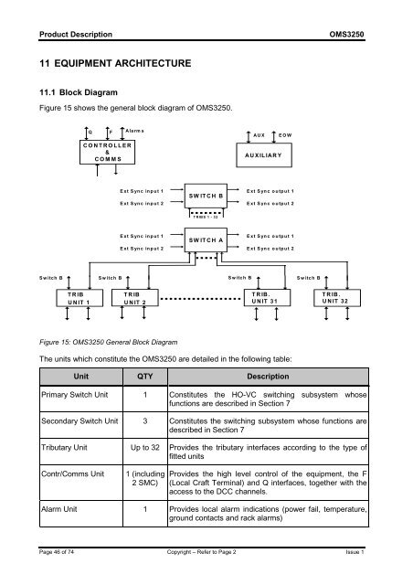
Product Description<strong>OMS</strong><strong>3250</strong>11 EQUIPMENT ARCHITECTURE11.1 Block DiagramFigure 15 shows the general block diagram of <strong>OMS</strong><strong>3250</strong>.QFCONTROLLER&COMMSAlarmsAUXA UXILIARYEOWExt Sync inp ut 1Ext Sync inp ut 2SWITCH BExt Sync outp ut 1Ext Sync outp ut 2T RIBS 1 - 32Ext Sync inp ut 1Ext Sync inp ut 2SWITCH AExt Sync outp ut 1Ext Sync outp ut 2Switch B Switch B Switch BSwitch BTRIBUNIT 1TRIBUNIT 2TRIB.UNIT 31TRIB.UNIT 32Figure 15: <strong>OMS</strong><strong>3250</strong> General Block DiagramThe units which constitute the <strong>OMS</strong><strong>3250</strong> are detailed in the following table:Unit QTY DescriptionPrimary Switch Unit 1 Constitutes the HO-VC switching subsystem whosefunctions are described in Section 7Secondary Switch Unit 3 Constitutes the switching subsystem whose functions aredescribed in Section 7Tributary Unit Up to 32 Provides the tributary interfaces according to the type offitted unitsContr/Comms Unit1 (including2 SMC)Provides the high level control of the equipment, the F(Local Craft Terminal) and Q interfaces, together with theaccess to the DCC channels.Alarm Unit 1 Provides local alarm indications (power fail, temperature,ground contacts and rack alarms)Page 46 of 74 Copyright – Refer to Page 2 Issue 1