OMS 3250
OMS 3250
OMS 3250
- No tags were found...
You also want an ePaper? Increase the reach of your titles
YUMPU automatically turns print PDFs into web optimized ePapers that Google loves.
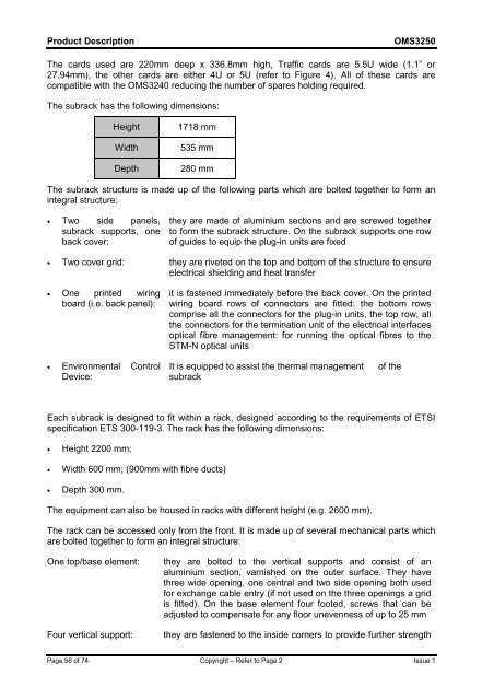
Product Description<strong>OMS</strong><strong>3250</strong>The cards used are 220mm deep x 336.8mm high, Traffic cards are 5.5U wide (1.1” or27.94mm), the other cards are either 4U or 5U (refer to Figure 4). All of these cards arecompatible with the <strong>OMS</strong>3240 reducing the number of spares holding required.The subrack has the following dimensions:HeightWidthDepth1718 mm535 mm280 mmThe subrack structure is made up of the following parts which are bolted together to form anintegral structure:• Two side panels,subrack supports, oneback cover:they are made of aluminium sections and are screwed togetherto form the subrack structure. On the subrack supports one rowof guides to equip the plug-in units are fixed• Two cover grid: they are riveted on the top and bottom of the structure to ensureelectrical shielding and heat transfer• One printed wiringboard (i.e. back panel):it is fastened immediately before the back cover. On the printedwiring board rows of connectors are fitted: the bottom rowscomprise all the connectors for the plug-in units, the top row, allthe connectors for the termination unit of the electrical interfacesoptical fibre management: for running the optical fibres to theSTM-N optical units• Environmental ControlDevice:It is equipped to assist the thermal managementsubrackof theEach subrack is designed to fit within a rack, designed according to the requirements of ETSIspecification ETS 300-119-3. The rack has the following dimensions:• Height 2200 mm;• Width 600 mm; (900mm with fibre ducts)• Depth 300 mm.The equipment can also be housed in racks with different height (e.g. 2600 mm).The rack can be accessed only from the front. It is made up of several mechanical parts whichare bolted together to form an integral structure:One top/base element:Four vertical support:they are bolted to the vertical supports and consist of analuminium section, varnished on the outer surface. They havethree wide opening, one central and two side opening both usedfor exchange cable entry (if not used on the three openings a gridis fitted). On the base element four footed, screws that can beadjusted to compensate for any floor unevenness of up to 25 mmthey are fastened to the inside corners to provide further strengthPage 56 of 74 Copyright – Refer to Page 2 Issue 1


