TROUBLE SHOOTING AIDSSWEEPLOSS OF SWEEPHORIZONTALFollow procedure outlined under"L6ss of High Voltage".INSUFFICINET SWEEPCheck by substitution V16, V17, VIS, V20 and V<strong>21</strong>. Check adjustments B3,B4 and B5. Check waveform'W16.If SatisfactoryCheckClie, C119, C120, C117, R119,T2, T4A and other associatedcomponents.DRIVE LINESIf UnsatisfactoryCheck R114, R116, C115 and otherassociated circuit components.Check adjustment B3. Check by substitution V16, V17 and V18. Check C114,C115, C119, C120,C123 , T2, T4A and other associated circuit componentsfor failure or change of value.COMPRESSED LEFT SIDECheck by substitution V16, V17 and V18. Check adjustments B3, B4 andB5. Check components associated with the horizontal output and damperstages especially T2 and T4A.FOLDSFollow procedure outlined under "Drive Lines".PIE CRUST EFFECTCheck V17 and V18 for internal arcing. Check T2, T4A, T5 and T6 forinternal arcing.XMAS TREE EFFECTSubstitute V16. Check L43, Clll, C110, C115, C114 and other associated componentsfor failure or change of value.LOSS OF SWEEPVERTICALCheck by substitution V14 and V1B. Check waveform Wll.If SatisfactoryCheck T3, T4B, and otherassociated components.INSUFFICINET SWEEPIf UnsatisfactoryCheck C91, C94, C95, C96, 'C93.R90, R96, R99 and other associatedcomponents.Check adjustment of height and vertical linearity controls. Proceed asoutlined under "Loss of Sweep".COMPRESSED AT BOTTOMCheck by substitution V14 and V15. Check T3, T4B and other associatedcomponents for failure or change of value.COMPRESSED AT TOPCheck by substitution V14 and V15. Check R94, H96, R99, R92, R93, R8C94, C95, C96, C93 and other associated circuit components.Check by substitution V14 and V15. Check components associated withV14B and V15 including T3 and T4B.SYNCLOSS OF VERTICAL AND HORIZONTAL SYNCCheck by substitution V6, V7, V8 and V14. Check coupling capacitors^plateload resistors, and grid resistors associated with these stages.LOSS OF VERTICAL SYNC-HORIZONTAL SYNC SATISFACTORYCheck by substitution V7 and V14. Check waveform W9.If SatisfactoryCheck components associated withV14B.If UnsatisfactoryCheck vertical integrator networkand other associated components.Check video IF stages for overloading.LOSS OF HORIZONTAL SYNC-VERTICAL SYNC SATISFACTORYCheck by substitution V6 and V16. Check associated components especiallyL43, Bill, R114, C110, C115 and C103.HORIZONTAL BENDINGCheck by substitution VI6 and V17. Check the horizontal AFC filter networkfor component failure or change of value.VIDEOLOSS OF VIDEOCheck by substitution V7 and V8. Check components associated with V7A andV8A for failure or change of value. Check contrast control and picture tube.SOUND BARS (4. SMC BEAT)Adjust tuner fine tuning for best picture and sound. Check adjustment A48.Check video IF alignmentPOOR CONTRASTCheck by substitution V6, V7 and V8. Check contrast control, picture tubeand other associated circuit components.NEGATIVE PICTURECheck adjustment of the AGC control. Check by substitution V8, V7, V6,V4, V3 and VI. Check AGC network. Check components associated with thetuner and-IF strip. Check picture tube and other associated components.SMEARCheck by substitution V6, V7 and V8. Check peaking coils, plate load resistors,grid load resistors, contrast control, coupling capacitors and other componentsassociated with VBA, V7A and V8A. Check picture tube.WIDE BLACK BAR ACROSS PICTURECheck VI, V3, V4, V5, V7 and V8 for heater to cathode leakage.AUDIOWEAK OR NO SOUNDCheck by substitution V9, V10, Vll, V12 and V13. Check stages V12 and V13using audio signal generator. Apply audio signal across R69.If SatisfactoryCheck ratio detector and audioIF alginment and circuit components.If UnsatisfactoryCheck components associated with V12and V13 especially C78 and T7.BUZZAdjust tuner fine tuning for best picture and sound. Adjust A45 for minimumbuzz. If still unsatisfactory, substitute Vll and realign ratio detector and audioIF stages. Check C67, C71 and C70.DISTORTEDFollow procedure outlined under "Weak or No Sound".PAGE 12
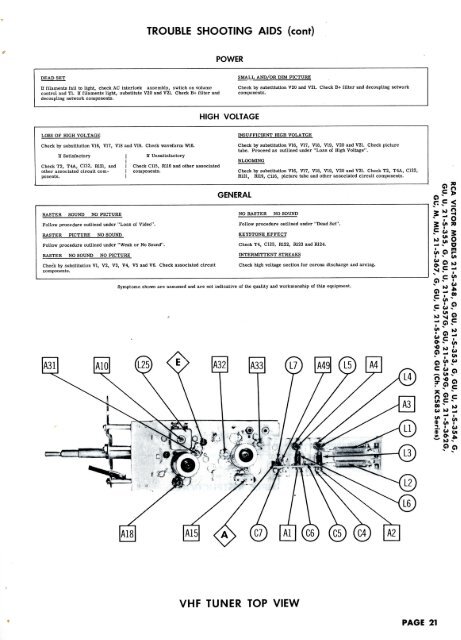
TROUBLE SHOOTING AIDS (cont)POWERDEAD SETIf filaments fail to light, check AC interlock assembly, switch on volumecontrol and Tl. If filaments light, substitute V20 and V<strong>21</strong>. Check B+ filter anddecoupling network components.SMALL AND/OR DIM PICTURECheck by substitution V20 and V<strong>21</strong>. Check B+ filter and decoupling networkcomponents.HIGHVOLTAGELOSS OF HIGH VOLTAGECheck by substitution V16, VI7, VI8 and V19. Check waveform W16.If SatisfactoryCheck T2, T4A, C122, R1<strong>21</strong>, andother associated circuit components.If UnsatisfactoryCheck C115, R116 and other associatedcomponents.INSUFFICIENT HIGH VOLATGECheck by substitution V16, V17, V18, V19, V20 and V<strong>21</strong>. Check picturetube. Proceed as outlined under "Loss of High Voltage".Check by substitution V16, V17, V18, V19, V20 and V<strong>21</strong>. Check T2, T4A, C122,R1<strong>21</strong>, R119, C116, picture tube and other associated circuit components.GENERALRASTER SOUND NO PICTUREFollow procedure outlined under "Loss of Video".RASTER PICTURE NO SOUNDFollow procedure outlined under "Weak or No Sound".RASTER NO SOUND NO PICTURECheck by substitution VI, V2, V3, V4, V5 and V6. Check associated circuitcomponents.NO RASTER NO SOUNDFollow procedure outlined under "Dead Set".KEYSTONE EFFECTCheck T4, C123, R122, H123 and R1<strong>24.</strong>INTERMITTENT STREAKSCheck high voltage section for corona discharge and arcing.Symptoms shown are assumed and are not indicative of the quality and workmanship of this equipment.6l~o V >sS;!FogSgc vi c ^VHP TUNER TOP VIEWPAGE <strong>21</strong>