RCA-21-S-348-Sams-24.. - Early Television Foundation
RCA-21-S-348-Sams-24.. - Early Television Foundation
RCA-21-S-348-Sams-24.. - Early Television Foundation
- No tags were found...

Create successful ePaper yourself
Turn your PDF publications into a flip-book with our unique Google optimized e-Paper software.
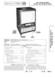
PHOTO FACT* FolderO ft>VOLUMECONTROLON-OFFSWITCHCONTRASTCONTROLCHANNELSELECTORFINETUNING<strong>RCA</strong> VICTOR MODEL <strong>21</strong>-S-354TRADE NAME <strong>RCA</strong> Victor MODELS CHASSIS TUNERMANUFACTURERTYPE SETTUBESPOWER SUPPLYTUNING RANGE -Alignment Instructions 5 thru 8Disassembly Instructions 22Horizontal Sweep Circuit Adjustments 13Parts List and Descriptions 15 thru 19PhotographsCabinet-Rear ViewCapacitor Identification134, 9Chassis-Top ViewRF Tuner314, <strong>21</strong>Resistor Identification 23, 24<strong>21</strong>-S-362M, <strong>21</strong>-S-367 KCS83 .. , KRK29<strong>21</strong>-S-362MU, <strong>21</strong>-S-367U KCS83A .KRK29A/27<strong>21</strong>-S-354 KCS83C .............. ... KRK29B<strong>21</strong>-S-353, <strong>21</strong>-S-355 KCS83C ........ ..... KRK29<strong>21</strong>-S-353G, <strong>21</strong>-S-354G, <strong>21</strong>-S-355G,<strong>21</strong>-S-357G, <strong>21</strong>-S-359G, <strong>21</strong>-S-362G KCS83C or KCS83PC - "G", KRK29<strong>21</strong>-S-367G, <strong>21</strong>-S-369G KCS83PK KRK22C<strong>21</strong>-S-353U, <strong>21</strong>-S-354U, <strong>21</strong>-S-355U ....... KCS83DKRK29A/27<strong>21</strong>-S-353GU, <strong>21</strong>-S-354GU, <strong>21</strong>-S-355GU,<strong>21</strong>-S-357GU, <strong>21</strong>-S-359GU, <strong>21</strong>-S-362GU,<strong>21</strong>-S-367GU, <strong>21</strong>-S-369GU<strong>21</strong>-S-<strong>348</strong>, <strong>21</strong>-S-<strong>348</strong>GKCS83D or KCS83PD - "GU"... KRK29A/27KCS83PJ .KRK29<strong>21</strong>-S-<strong>348</strong>G KCS83PL KRK22C<strong>21</strong>-S-<strong>348</strong>GU ... .......... KCS83PM KRK29A/27<strong>RCA</strong> Victor Div., Radio Corp, of America, Camden, N.J.<strong>Television</strong> ReceiverTwenty-two110-120 Volts AC-60 Cycle • RATING 1.9 Amp. ® 117 Volts ACChannels 2 thru 13 VHF, 14 thru 83 UHF, Video IF 45.75MC, Sound IF 41.25MC (Intercarrier)INDEXPhotographs (Cont)Trans., Inductor & Alignment Identification ...... 19Resistance Measurements 11Servicing in the Field 22Schematic (Alternate Tuners)....................... 20,25Schematic (TV) 2Trouble Shooting Aids ............................. 12, <strong>21</strong>Tube Failure Check Chart ............................. 10Tube Placement Chart (Bottom View) 11Tube Placement Chart (Top View) 105- »Ul >KiOiOy» o 2feoBNl C WO C v>* * COO K> £C 7^ 00> w» >c co O> 01 Nb> N oT Q cSoy* c r«o> v»O K> toN T Oi^> A >8>^C ooto w w2. CO to Oiu> u Jk^O^HOWARD W. SAMS & CO., INC. • Indianapolis 5, Indiana"The listing of any available replacement part herein does not constitute in anycase a recommendation, warranty or guaranty by Howard W. <strong>Sams</strong> & Co., Inc.,os to the quality and suitability of such replacement part. The numbers of theseparts hove been compiled from information furnished to Howard W. <strong>Sams</strong> & Co.,Inc., by the manufacturers of the particular type of replacement part listed.""Reproduction or use, without express permission, of editorial or pictorial content,in any manner, is prohibited. No patent liability is assumed with respect tothe use of the information contained he-rein. Copyright 1954 by Howard W.<strong>Sams</strong> & Co., Inc., Indianapolis 5, Indiana, U. S. of America. Copyright under InternationalCopyright Union. All rights reserved under Inter-American CopyrightUnion U 910) by Howard W. <strong>Sams</strong> & Co., Inc." Printed in U. S. of AmericaDATE 6-54 SET 242 FOLDER 8
CHANNEL SELECTOR SWITCH SHOWN IN CHAHNSW ONVOLUMECONTROL^ScBLJbRIORED280VACLV RECT»)5U4G• MKASURED KttOl§ 4-RED-GR«N WITH CONTROLSA PHOTOFACT STANDARD NOTATION SCHEMATIC©Howard W. Som! & Co., Inc. 1954PAGE 2
©]_IMM" ^-Ng&j:@IZ©i, i @,. ''> i©-L.,, '•&!-
,,A Hi<strong>RCA</strong> VICTOR MODELS <strong>21</strong>-S-<strong>348</strong>, G, GU, <strong>21</strong>-S-353, G, GU, U, <strong>21</strong>-S-354, G,GU, U, <strong>21</strong>-S-355, G, GU, U, <strong>21</strong>-S-357G, GU, <strong>21</strong>-S-359G, GU, <strong>21</strong>-S-362G,GU, M, MU, <strong>21</strong>-S-367, G, GU, U, <strong>21</strong>-S-369G, GU (Ch. KCS83 Series)
<strong>RCA</strong> VICTOR MODELS <strong>21</strong>-5-<strong>348</strong>, G, GU, <strong>21</strong>-S-353, G, GU, U, <strong>21</strong>-S-354, G,GU, U, 2 1 -S-355, G, GU, U, <strong>21</strong>-S-357G, GU, 2 1 -S-359G, GU, <strong>21</strong> -S-362G,GU, M, MU, <strong>21</strong>-S-367, G, GU, U, 2 1-S-369G, GU (Ch. KCS83 Series)M3IA dOl SISSVHD
uUJo00tr tn
<strong>RCA</strong> VICTOR MODELS <strong>21</strong>-S-<strong>348</strong>, G, GU, <strong>21</strong>-5-353, G, GU, U, <strong>21</strong>-S-354, G,GU, U, <strong>21</strong>-S-355, G, GU, U, <strong>21</strong>-S-357G, C»U, <strong>21</strong>-S-359G, GU, <strong>21</strong>-S-362G,GU, M, MU, <strong>21</strong>-S-367, G, GU, U, <strong>21</strong>-S-369G, GU (Ch. KCS83 Series)~ u zLUQoe,O^u
ALIGNMENT INSTRUCTIONSALIGNMENT INSTRUCTIONS-READ CAREFULLY BEFORE ATTEMPTING ALIGNMENTThe high voltage shock hazard may be eliminated by removing the horizontal oscillator tube (V16) from its socket.KRK29 OR KRK29A ANTENNA MATCHING UNIT ALIGNMENTThe antenna matching unit has been properly aligned at the factory. The RF unit is aligned with a particular antenna matching unitIn place.If a new antenna unit is installed, the RF unit should be realigned. Alignment should not be attempted without the proper alignmentfacilities.The FM trap, L7, may be aligned without adversely affecting the alignment of the unit. Disconnect the lead from the FM trap (L7)to the channel selector switch. Use a short jumper to connect point ^A\n the matching unit thru a .001MFD capacitor to pin 1(grid) of 6CF6 (V4). Remove 6CF6 (V3) from its socket. N/The matching unit cover must be in place during alignment. Connect the ends of a lOOOSi potentiometer across a 7.5 volt batterycapable oLwithstanding considerable current drain. Connect the positive terminal to chassis and connect the potentiometer armto point U^ . Set the potentiometer arm to obtain -5 volts at point U^.Connect the synchronized sweep voltage from the sweep generator to ule horizontal input of the oscilloscope for horizontal deflection.The sweep generator output lead should be terminated with its characteristic impedance, usually 50 ohms.DUMMYANTENNASWEEPGENERATORCOUPLINGTwo 130 n Across antenna terminalswith 130J2 in eachCarbonResistors lead.SWEEPGENERATORFREQUENCY50MC(20MC Swp)MARKERGENERATORFREQUENCY45.75MC(400tiMod)41.25MC(4001, Mod)50MC52MC53MCCHANNELAnyCONNECTSCOPEVert. Amp. to point . Low side toADJUSTVert. Amp. thru A3,A4detector (Fig.l) topointOv> . Low sideto chassis.KRK22C ANTENNA MATCHING UNIT ALIGNMENT (CH.KCS83PK & KCS 83PL)REMARKSSet scope gain for maximum. Turn AGC.Adjust for MINIMUM 4000, response onscope.Remove the .001MFD capacitor (see instructionsabove) from pointO^andconnect a 300O, 2 watt carbon resistor frompoint^^to chassis using very short leads,,Adjustuj obtain response curve similar toFig. 2. Repeat steps 1, 2 and 3 until nofurther improvement is noted. Remove the300(2 resistor and detector probe. Restoreconnection between L7 and the channelswitch. Replace V3 in its socket.The antenna matching unit has been properly aligned at the factory. The RF unit is aligned with a particular antenna matching unit in place. If anew antenna unit is installed, the RF unit should be realigned. Alignment should be attempted wtthout the proper alignment facilities. The FMtrap (A49) may be aligned without adversely affecting the unit. Disconnect the lead from pointO^to the channel selector switch. Use a shortjumper to connect point Vvon *-ne matching unit through a . 001MFD capacitor to Pin 1 (grid) of tne second video IF amplifier (6CF6). Removethe first video IF amplifier (6CF6) from its socket. The matching unit cover must be in place during alignment.Connect the ends of a lOOOfi potentiometer across a 7. 5 volt battery capable of withstanding considerable current drain. Connect the positiveterminal to chassis and connect the potentiometer arm to point^N. Set the potentiometer arm for -5 volts at polnt^N. Follow the procedureoutlined under steps 1, 2 and 3 for "KRK29 or KRK29A antenna matching unit alignment.Connect the synchronized sweep voltage £rom the sweep generator to the horizontal input of the oscilloscope for horizontal deflection.The sweep generator output lead should be terminated with its characteristic impedance, usually 50 ohms.VIDEO IF ALIGNMENT (MODELS <strong>21</strong>-S-354 & <strong>21</strong>-S-362, MODELS <strong>21</strong>-S-<strong>348</strong>THRU <strong>21</strong>-S-369)Leave bias connected as under " antenna matching unit alignment ". Turn AGC control fully clockwise Models <strong>21</strong>-S-<strong>348</strong> through <strong>21</strong>-S-369 incorporatethree printed circuit type video IF transformers. Location of these transformers and their A numbers is shown in Fig. 6.Connect the synchronized sweep voltage from the sweep generator to the horizontal input of the oscilloscope for horizontal deflection.DUMMYANTENNADirect". 0015MFDCeramicCapacitorSWEEPGENERATORCOUPLINGHigh side to terminal'A" of L27. Low sideto terminal * B".""High side to point
ALIGNMENT INST4.5.6.7.8.9.10.111<strong>21</strong>3VIDEO IF ALIGNMENT (MODELS <strong>21</strong>-S-354U THRU <strong>21</strong>-S-362U, MODELS <strong>21</strong>-S-<strong>348</strong>U THRU <strong>21</strong>-S-369U)Leave bias connected as under " antenna matching unit alignment Turn AGC control fully clockwise. Models <strong>21</strong>-S-<strong>348</strong>U thru <strong>21</strong>-S-369U incorporatehree printed circuit tube video IF transformers. Location of these transformers and their A numbers Is shown In Fig. 6.DUMMYSWEEPSWEEP MARKERNTENNA GENERATORGENERATOR GENERATOR CHANNELCONNECTCOUPLINGFREQUENCY REQUENCYSCOPEADJUSTREMARKSDirect High side to terminal Not used 44. SMC Any not Use VTVM.A5 Attenuate generator output to maintain -3*A" of first video IFused DC probe to pointu» volts at VTVM. Adjust for maximumransformer. Low sidelocally Common to chassis.deflection.to terminal *B".""0015MFD High sWe to point .eramlc jow side to tunercapacitor chassis. Use very shorteads.loooo High side thru dummyCarbon to rear terminal of 1N82Resistor crystal holder. LowIn series side to tuner chassis.with Use very short leads.. 0015MMFDceramiccapacitoiTwo 130nCarbonResiator"Across VHF antennaterminals with 130R Ineach lead."44MC(10MC Swp)44MC(10MC Swp)<strong>21</strong>3MC267MC(10MC Swp)201MC(10MC Swp)186MC(10MC Swp)189MC(10MC Swp)1B3MC(10MC Swp)177MC(10MC Swp)85MC(10MC Swp)79MC(10MC Swp)69MCOOMC Swp)63MC(10MC Swp)57MC(10MC Swp)45. SMC3.0MC47.25MC2. SMC5.75MC7.25MC2. SMC5.0MC5.75MC6. SMC41.2SMC4S.75MC2U.25MC<strong>21</strong>5.75MC205.25MC209.75MC199.2SMC203.75MC193.25MC197. 7 SMC187.25MC191.75MC181.25MC185.7BMC175.25MC179.75MC83.25MC87.75MC77. 2 SMC81.75MC67. 2 SMC71. 7 BMC61.25MC65.75MC55.26MCS9.75MC""447(670MC)131<strong>21</strong>11098765432"Vert. Amp. thrudetector (Fig.l) topin 5 (plate) of firstvideo IF amp. Lowside to chassis.Veri. Amp. to pointGh . Low side tochassis.Vert. Amp. thru A12,A13detector (Fig.l) tojunction of 180n resistorand .0015MFDcapacitor at pointoS . {See remarksLow side to tunerchassis.Vert. Amp. to point^^ . Low side tochassis.VerL Amp. to pointQ« . Low side tochassis.A6A7A8A10,AUA9"Use sufficient generator output to produce-3 volts at VTVM. Adjust for MINIMUMdeflection.Connect 330S2 carbon resistors across primariesof third and fourth video IF transormers.Preset A9 to MINIMUM capacity.Connect 1800 carbon resistor across primaryof second video IF transformer. Couplea second signal generator loosely to detectorirobe (Fig.,1) to furnish markers. Attenuatesweep output to maintain 0.3 volts peak topeak for final adjustments. Adjust A10 and Allor maximum gain with 45.75MC marker at5%, Adjust A9 to place 42, SMC marker at'0% on response curve as shown in Fig. 3.Remove detector probe , the 18011 and thetwo 300 resistors.Adjust sweep generator output for 3 volts peako peak on scope. Couple the marker generatorloosely to grid of first video IF ampllier.Retouch A5, A6 and A7 to obtain reponsecurve similar to Fig. 4.Set UHF changeover switch to UHF position.Connect a .0015MFD capacitor iiLserles with180S1 carbon resistor from point^^ tochassiswith the capacitor end connected topolnt^K? . Couple second signal generator todetector probe (Fig.l) to furnish markers.Connect the potentiometer arm of a secondbias supply to the tuner AGC terminal. Connectpositive side to chassis. Adjust for -3volts at tuner AGC terminal. Attenuatesweep generator output to produce 0.3 voltpeak to peak on scope . Adjust A12 and A13for maximum gain with video and soundmarkers not lower than 90% or responsecurve as in Fig. 5. Remove resistor,capacitor and detector probe from point ^y •Attenuate sweep generator output to maintain3 volts peak to peak on scope. Ifnecessary, retouch A12 and A13 only toobtain response similar to Fig. 5.Couple marker generator loosely to gridof first video IF amplifier. Leave theAGC bias at -3 volts and the IF bias at-5 volts. Check all channels for responsesimilar to Fig. 4. If necessary, SLIGHTLYretouch A5 and A6 to correct any overalltilt that is essentially the same on allchannels.Remove VHF sweep generator and connect UHF sweep generator to antenna terminals. Check all UHF channels for response similar to Fig. 4. Ifnecessary, SLIGHTLY retouch AS and A6 to correct any overall tilt. Disconnect generators and bias supplies. •F IG.4F IG.7FIG.
1U <strong>21</strong>-3-362U, MODELS <strong>21</strong>-S-<strong>348</strong>U THRU <strong>21</strong>-S-369U)ully clockwise. Models <strong>21</strong>-S-<strong>348</strong>U thru <strong>21</strong>-S-369U incorporatetheir A numbers Is shown in Fig. 6.NECT:>PElfto point^^o chassis.ADJUSTA5A6REMARKSAttenuate generator output to maintain -3volts at VTVM. Adjust for maximumef lection.ALIGNMENT INSTRUCTIONS (cont)14.KHK29B TUNER ALIGNMENT (MODE)An RF unit which is operative and requires only minor touch-us necessary make the following adjustments.Jre-set A14 all the way out. Set channel 7 to 13 oscillator slugsrom terminals "A" and"B" of L27 (first video IF trans) and te:["uner alignment as outlined below requires the use of a heteroiConnect the synchronized sweep voltage from the sweep genera'he sweep generator output lead should be terminated with Its cDUMMYANTENNADirectSWEEPGENERATORCOUPLINGHigh side to point .Low side to chassis.SWEEPGENERATORFREQUENCYNot usedMARKERGENERATORFREQUENCY43. SMC(400%Mod)). thrurig.1) toe) of firstmp. Lowissis.>. to pointw side to7A810, All9Ise sufficient generator output to produce3 volts at VTVM. Adjust for MINIMUMdeflection.Connect 330(2 carbon resistors across primariesof third and fourth video IF transormers.Preset A9 to MINIMUM capacity.Connect 180S2 carbon resistor across primaryof second video IF transformer. Couplesecond signal generator loosely to detectorrobe (Fig.l) to furnish markers,, Attenuateweep output to maintain 0.3 volts peak toteak for final adjustments. Adjust A10 and Allor maximum gain with 45.75MC marker at5%. Adjust A9 to place 420 BMC marker at0% on response curve as shown in Fig. 30lemove detector probe , the 1800 and thewo 300 resistors.Adjust sweep generator output for 3 volts peako peak on scope. Couple the marker genertorloosely to grid of first video IF ampliier.Retouch A5, A6 and A7 to obtain reponsecurve similar to Fig. 4.F IG.4F IG.51ST VIDEO IFAMP2ND VIDEO IFAMP3RD VIDEO IFAMP15.16.RF Input of heterodynefrequency meter to endof Insulated wire insertedin hole provided foradjustment of A17.Set freq.meter to227MCNOTE : If channel 8 oscillator frequency cannot be reached bythen switch to channel 12 and adjust A20 for channel 12 osclllatproper oscillator frequency on each channel. Also, on channelthen switch back to channel 8 and adjust A18 again.Two 130CCarbonResistorsAcross antenna terminalswith 130(2 ineach lead.183MC(10MC Swp)181.25MC185.75MCp. thru A12, A13Fig.l) toE 180H re-. .0015MFDat pointee remarksto tunerp. to point>w side toip. to point,ow side toSet UHF changeover switch to UHF position.Connect a . 0015MFD capacitor iiuseries with,8011 carbon resistor from point^f/tochassis with the capacitor end connected topointoy . Couple second signal generator toletectOT probe (Fig.l) to furnish markers.Connect the potentiometer arm of a second>las supply to the tuner AGC terminal. Connectpositive side to chassis. Adjust for -3volts at tuner AGC terminal. Attenuatesweep generator output to produce 0,3 voltjeak to peak on scope. Adjust A12 and A13or maximum gain with video and soundmarkers not lower than 90% or responsecurve as in Fig. 5. Remove resistor,capacitor and detector probe from point \fy .Attenuate sweep generator output to main-:aln 3 volts peak to peak on scope. Ifnecessary, retouch A12 and A13 only toobtain response similar to Fig. 5.Couple marker generator loosely to gridof first video IF amplifier , Leave theAGC bias at -3 volts and the IF bias at-5 volts. Check all channels for responsesimilar to Fig. 4. If necessary, SLIGHTLYretouch A5 and A6 to correct any overalltilt that is essentially the same on allchannels.FIG.6VIDEO DET17.18.19.20.<strong>21</strong>.Connect the DC probe of VTVM to point
RUCTIONS (cont)X"F IG.51ST VIDEO IFAMP2ND VIDEO IFAMP3RD VIDEO IFAMPVIDEO DET14.15.16.17.18.KRK29B TUNER ALIGNMENT (MODELS <strong>21</strong>-3-354 81 <strong>21</strong>-S-362, MODELS <strong>21</strong>-S-<strong>348</strong> THRU <strong>21</strong>-S-369C)Vn RF unit which is operative and requires only minor touch-up adjustments will require no pre-setting of adjustments. Where complete alignments necessary make the following adjustments.?re-set A14 all the way out Set channel 7 to 13 oscillator slugs one turn from tight. Adjust A10 so that slug s all the way out. Disconnect the linkrom terminals "A" and"B" of L27 (first video IF trans) and terminate the link with a 39£1 carbon resistor.Tuner alignment as outlined below requires the use of a heterodyne frequency meter.Connect the synchronized sweep voltage from the sweep generator to the horizontal input of the oscilloscope for horizontal deflection.The sweep generator output lead should be terminated with its characteristic impedance, usually 50 ohms.DUMMYANTENNADirectSWEEPGENERATORCOUPLINGHigh side to point ^A\Low side to chassis/RF input of heterodynefrequency meter to endof insulated wire Insertedin hole provided foradjustment of A17.SWEEPGENERATORFREQUENCYNot usedMARKERGENERATORFREQUENCY43.5MC(400Wod)Set froq.meter to227MCCHANNEL28CONNECTSCOPEVert. Amp. to point . Low side tochassis.Not usedADJUSTA15A18, A14REMARKSShort the tuner AGC terminal to ground.Adjust scope for maximum gain and signalgenerator for maximum output. Adjust A15for MINIMUM 400t, Indication on scope.Remove short from AGC terminal.Connect the potentiometer arm of the biassupply to the tuner AGC terminal. Connectthe positive lead to tuner chassis , Adjustfor -3 volts at tuner AGC terminal. PresetA16 for -3 volts on VTVM at pointU^ .(Limits ol oscillator injection voltage aretwo 5.5 volts) o Turn fine tuning controlfully clockwise. Adjust A18 for audible beaton frequency meter. Adjust A14 clockwiseuntil beat note just begins to change, thenturn one full turn in same clockwise directioiReturn fine tuning control to Its mid-rangeposition.NOTE: If channel 8 oscillator frequency cannot be reached by adjustment of A18 switch to channel 13 and adjust A19 for channel 13 oscillator frequency,then switch to channel 12 and adjust A20 for channel 12 oscillator frequency. Continue down to channel 8 adjusting proper oscillator trimmer to obtainproper oscillator frequency on each channel. Also, on channel 8t adjust A18 for channel 8 oscillator frequency. Switch to channel 13 and adjust A19 ,then switch back to channel 8 and adjust A18 again.Two 130fCarbonlesistorsAcross antenna terminalswith 130(1 ineach lead.183MC(10MC Swp)181.25MC185.75MC8 Vert. Amp. to point«K . Low side tochassis.A31, A17,A32,A33Set AID to maximum counter clockwiserotation. If a separate marker generator isused connect it loosely to antenna terminals.Adjust scope for maximum gain and attenuatesweep generator output for a MINIMUMsignal Input to produce useable pattern onscope. Adjust A31, A17.A32 and A33 forresponse similar to Fig. 7,Connect the DC probe of VTVM to point . Readjust A14, A17, A31 and A32 for responsesimilar to Fig. 7. Adjust A33 for maximum gain at mid-point of response curve. If necessary, repeat until desired response is obtained.Connect frequencymeter as in step 15.Not usedFreq.meter to257MC13Not usedA19Turn fine tuning control fully clockwise .Adjust A19 for audible beat on frequencymeter. SLIGHTLY overshoot the adjustmentan additional turn in the same direction,and then adjust A14 to again obtain anaudible beat.19.Two 130ftCarbonlesistorsAcross antenna terminalswith 13 00 ineach lead.<strong>21</strong>3 MC(10MC Swp)<strong>21</strong>1.25MC<strong>21</strong>5,75MCVerJ. Amp. to pointVo. Low side tochassis.A34A3 5Adjust for response similar to Fig. 7,Turn off generator and check oscillatorinjection voltage at point «]Nwith VTVM.Voltage should be within limits (2-5.5volts). If A16 required readjustment turnsweep generator back on and recheckchannel 13 response. If necessary, retouchA34 and A35 to obtain desired response.20.Connect frequency meteras in step 15.Not usedFreq.meter to227MC8Not usedA14Check for audible beat on frequency meter.If necessary, readjust A14 for properoscillator frequency*F IG.8<strong>21</strong>.Two 1300CarbonResistorsAcross antenna terminalswith 130O ineach lead.183MCUOMC Swp)181.25MC185. 7 SMCVerl. Amp. to point«O , Low side tochassis.A31, A17A32A33If necessary, retouch A31, A17, A32 andA33 to obtain response similar to Fig. 7.If A31 required adjustment turn offgene rator and switch back to channel 13and check oscillator Injection voltage atpolnt«hwith VTVM. If the oscillatorinjection trimmer, A16, was far off it maybe necessary to repeat steps 20 and <strong>21</strong>several times before proper setting ofA16 Is obtained.22Connect frequencymeter as in step 15.Not usedFreq.meter to129MC6Not usedA2GSet fine tuning control to its mid-rangeposition. Adjust A26 for audible beaton frequency meter.23Two 13 012CarbonResistorsAcross antenna terminalswith 130O ineach lead.85MC(10MC Swp)83.25MC87.75MCVert. Amp. topoint ttN . Low sideto chassis.A36A3 7A38Adjust for response similar to Fig. 7.Check oscillator injection voltage at point«Swlth VTVM. If necessary, readjustAloT If A1G required readjustment switchthe receiver and generator to channel 8If necessary, retouch A31 for responsesimilar to Fig. 6. Recheck A14 and A18for proper oscillator frequency as instep 15 .24Across antenna terminalswith 130O ineach lead.79MC(10MC Swp)69MC(10MC Swp)63 MC(10MC Swp)57MC(10MC Swp)77.25MC81.75MC67.25MC71. 75MC61. 2 BMC65.75MC55.25MC59.75MC5432VerL Amp. to point«N . Low side tochassis.Check for response similar to Fig. 6. Ifmarkers fall below 80% on any channel retouchA36 and A37 for best compromiseon all low band channels . Check oscillatorinjection voltage at point «j>with VTVM.It should be within limits oT2 to 5.5 volts .PAGE 7
25.26.272829DUMMYANTENNATwo 13 OSJCarbonResistor30SWEEPGENERATORCOUPLINGAcross antenna terminalswith 130SJ inConnect frequencymeter as In step 15.ALIGNMENT INSTRUCTIONS (cont)SWEEPGENERATORFREQUENCY<strong>21</strong>3 MCMMC Swp)207MC(10MC Swp)201MC(10MC Swp)195MC(10MC Swp)189MC(10MC Swp)183MCaOMC Swp)177MC(10MC Swp)Not usedMARKERGENERATORFREQUENCY<strong>21</strong>1.25MC<strong>21</strong>5.75MC205.25MC209.75MC199.25MC203.75MC193.25MC197.75MC187.25MC191.75MC181. 25MC185.75MC175.25MC179.75MCFreq.meter to257MC251MC245MC239MC233MC227MC2<strong>21</strong>MC129MC123MC113MC107MC101MCCHANNEL131<strong>21</strong>110987131<strong>21</strong>11098765432CONNECTSCOPEVert. Amp. to point . Low side tochassis.Not usedADJUSTA17A3IA32A19A20A<strong>21</strong>A22A23A24A25A26A27A28A29A30fiZU. MOIREMARKSCheck for response similar to Fig. 6. Ifmarkers fall below 80% retouch A17, A31,and A32 for best compromise on all highband channels. Check oscillator injectionvoltage at point with VTVM. It shouldbe within limits oT2 to 5. 5 volts.Adjust Individual channel oscillator slugfor audible beat on frequency meter oneach channel. Check oscillator Injectionvoltage at point vT>on each channel toverify that the voltage Is within limits(2-5.5volts). Continue alignment withstep 30.)ELS <strong>21</strong>-S-<strong>348</strong>U THRU <strong>21</strong>-S-369GU' The VHF alignment procedure for the KRK29A tuner is Identical^ alignment procedure lor KRK29B tuner. Perform the tndicated operations outl.neatn steps 14 through 26 under "KRK29B tuner alignment" ....... r — 'Ground the IF transformer, whose adjustment is A12, by connecting one end of a clip lead to tuner chassis and Inserting the opposite end through theaperature provided on top of the tuner.If the oscilloscope available does not have a sensitivity of 0. 03 volts per Inch a suitable amplifier may be used.Fabricate a test dial with marks scrlped on Us circumference at 0, 9, and 168 degrees. The dial should be made to fit over the split gear on thetuner shaft for accurate alignment Locate the 0 degree reference point with the capacitor plates fully meshed. To make certain that the platesare fully meshed, place a 1/16" shim between the stop pin on the tuner and the stop plate on the gear assembly.Connect the high side of the VHF marker signal generator through a 1000S2 carbon resistor to the rear terminal of the 1N82 crystal holder .Connect the UHF marker generator loosely to antenna terminals.Connect the synchronized sweep voltage from the sweep generator to the horizontal input of the oscilloscope for horizontal deflection.The sweep generator output lead should be terminated with its character sttc impedance, usually 50 ohms.DUMMYANTENNATwo 130rCarbonResistorsSWEEPGENERATORCOUP1INGAcross antenna terminalswith 1300 Ineach lead.SWEEPGENERATORFREQUENCY887. SMC(Use Max.sweep width4 73. SMC(Use max.sweep width)MARKERGENERATORFREQUENCY4I.25MC43 . SMC45.75MC887. SMC41. 2 SMC43. SMC45.75MC4 73. SMCCHANNEL83(168 degreon tuningdial)14(9 degreeon tuningdial)CONNECTSCOPEVert. Amp. (thrupre-amp^if neededto pointoK. Lowside to chassis.ADJUSTA39A40A41A42A43A44REMARKSAdjust A39 and A40 for maximum amplitudeovercoupled response curve, centered at887. SMC, similar to Fig. 8. Adjust A41until 43. SMC marker coincides with887. SMC marker. The 41.25MC and 45.75MC markers should be symmetrically locatedon top of response curve as in Fig. 8.Adjust A42 and A43 for maximum amplitudeovercoupled response curve, centered at473. 5MC, similar to Fig. 9. Adjust A44until the 43. SMC marker coincides with473. SMC marker. The 41.25MC and 45.75MCmarkers should be symmetrically locatedon top of the response curve as in Fig. 9.If necessary repeat steps 27 and 28 untilproper responses are obtained.Tune thru entire UHF range and check tracking. If the 41.25MC and 45. 75MC markers fall below 70% on any UHF channel it will be necessary tobend the RF plates to correct the mistracking. The plates may be bent by inserting a knife blade thru the two holes provided on the left side of the tunerKnife the plates while tuning lower in frequency that tracking above the point of knifing will not be disturbed. A check of the section requiring knifingmay be made by touching the plates with the knifing tool while noting the effect on the response curve .Connect the DC probe of VTVM to pointoK Common to chassis. Tune thru the entire UHF range at the same time noting the reading on the VTVM.Headings between .05 and .4 volt should Be obtained. If voltages outside this limit are obtained it indicates low Bt voltage, low or high crystal impedanceor an oscillator tube outside allowable limlls. If the oscillator tube is replaced steps 27 and 28 should be repeated.KRK22C TUNER ALIGNMENTThe alignment procedure for the KRK22C tuner Is Identical to alignment for KRK29B Perform the indicated operattons outlined In steps 14 through 26[ under "KRK29B" tuner alignment .SOUND IF ALIGNMENT USING AM SIGNAL GENERATOR AND VTVMDUMMYANTENNA. 001MFDSIGNALGENERATORCOUPLINGHigh side to point .Low side to chassis.SIGNALGENERATORFREQUENCY4. SMC(Unmod)CHANNELAny noninterferingchannelCONNECTVTVMDC probe to point Common to chassis.ADJUSTA46REMARKSAttenuate generator output to maintain 6 volts atVTVM. Adjust for maximum deflection.31.3233""11"DC probe to point Common to chassis.DC probe to point .Common to chassis^4. SMC TRAP ALIGNMENTShort pin 1 (grid) of third video IF amplifier (6CB6) to ground.DUMMYANTENNAloonresistorSIGNALGENERATORCOUPLINGHigh side to point .Low side to chassis.SIGNALGENERATORFREQUENCY4.5MC(4001.Mod)CHANNELAnyCONNECTVTVMUse scope.Vert. amp. thrudetector (Fig. 1) topin 9 (plate) of 6X8(V7A) . Low side tochassis.A45A47ADJUSTA48Adjust for zero reading. A positive and negativereading will be obtained on either side of the correctsetting.0 Repeat steps 30 and 31.Attenuate generator output to maintain 6 volts at VTVM.Adjust for maximum deflection.REMARKSAdjust for MINIMUM 40CK indication on scope.Tune In a station and Inspect picture for 4. SMC beat interference. If 4. SMC beat interference is evident turn the fine tuning control slightly clockwiseto emphasize beat then adjust A48 for MINIMUM 4. SMC beat Interference in picture.FM TRAP ADJUSTMENTIf Inteference from a strong FM station is encountered, adjust A49 (on top of antenna matching transformer) tor MINIMUM Inteference In the picture.PAGE 8
TUBE PLACEMENT CHARTTUBE FAILURE CHECK CHARTThe following chart lists tubes whose failures are most likely to produce the indicated symptomsRefer to tube placement chart for location and type of tube.POWER SUPPLY FAILURENo raster, no sound - V20, V<strong>21</strong>LOSS OF PICTURE OR SOUNDNo pic, no sound, has raster - V2, V3, V4, V5, V6No pic, no sound, has snow - VI, V2, V3No pic, has sound, has raster - VI, V8, V22Has pic, no sound - V7, V10, TO, V12, V13Overloaded picture - V8, V12SYNC FAILURENo vert, sync - V7, V14No horiz. sync - V6, V14, V16No vert, or horiz. sync - V14SWEEP FAILURENo raster, has sound -V16, VH, V18, V19, V22, Fuse (Ml)No vertical deflection - V14, V15Poor vert, linearity or foldover - V14, V15Poor horiz. linearity or foldover - V16, V17, V18Narrow picture - V16, VII, V18, V19, V20, V<strong>21</strong>Vert, off freq. -VI, V14Horiz. off freq. - V6, V14, V16PAGE 10
RESISTANCE MEASUREMENTSItemV 1V 2V 3V4V 5V 6V7V8V 9V 10V 11V 12V13V14V 15V 16V 17V 18V 19V20V<strong>21</strong>V22Tube6BQ7A6X86CF66CF66CB612AU76X812AU76AU66AU66AL56AV66K6GT6SN7GT6K6GT6SN7GT6BQ6GT6AX4GT1B3GT5U4G5Y3GT<strong>21</strong>EP4APin 1tl. 5Knon44KH43KS2.3(22MegOS!260Kn8.5S<strong>21</strong>20KnlOKfilOMegINFtl.SMegINFl.SMegINFINFINFINFOnPin 2400KI2lOOKn6803317180n3.9KO2.2Meg4.5MegononlOKnonon•fl2.3Kn.int45K!JanINFPin 3soOKnt!2.5Knonon.in.30tl.2Megt4.3Knonononont2.2Knont525n410KnDJFIMegonon.in.10on.inPin 4ananan.inananti.8Knl.BMegt4on480KS2te.BKnINFananPin 5t4.8Knt4.8Kn|3.7Knanonant4.3KntiOKnINF350Kn470Kn«1.6Megl.SMegt47KnIMegt70nPin 6500KnonT4.8Knt4.8Kn|3.7Knt6.8KnI2ont7.5Knt4.3Knts.sxnon350KnINFonINFon2.2MegINFPIN 1 - 8 HAVE INF RESISTANCE60Kn60 Kn470KS2INFINFPIN 10-325JO2isn13 nPINUINFINFPIN 12an13 n13 ni70icnt MEASURED FROM PIN 8 OF V<strong>21</strong>. MEASURED FROM PIN 3 OF V18Pin 7350KnloOKnononontsoKn3.9Kn470Kn82 nonINFtsooKnananonanononINFINFI2onPin 8t!5.5Kn400KntioxniiKn5 eononononwonan60KneoxnonPin 9t!5.5KnonT22KHonTOP CAP-9QTOP CAP.naon= wi ._ mto O r-i - t/l(Vt\/CONVOL25LllOcSfietn C -00 kjw w -P oTUBE PLACEMENT CHARTSET 242 FOLDER !PAGE 11
TROUBLE SHOOTING AIDSSWEEPLOSS OF SWEEPHORIZONTALFollow procedure outlined under"L6ss of High Voltage".INSUFFICINET SWEEPCheck by substitution V16, V17, VIS, V20 and V<strong>21</strong>. Check adjustments B3,B4 and B5. Check waveform'W16.If SatisfactoryCheckClie, C119, C120, C117, R119,T2, T4A and other associatedcomponents.DRIVE LINESIf UnsatisfactoryCheck R114, R116, C115 and otherassociated circuit components.Check adjustment B3. Check by substitution V16, V17 and V18. Check C114,C115, C119, C120,C123 , T2, T4A and other associated circuit componentsfor failure or change of value.COMPRESSED LEFT SIDECheck by substitution V16, V17 and V18. Check adjustments B3, B4 andB5. Check components associated with the horizontal output and damperstages especially T2 and T4A.FOLDSFollow procedure outlined under "Drive Lines".PIE CRUST EFFECTCheck V17 and V18 for internal arcing. Check T2, T4A, T5 and T6 forinternal arcing.XMAS TREE EFFECTSubstitute V16. Check L43, Clll, C110, C115, C114 and other associated componentsfor failure or change of value.LOSS OF SWEEPVERTICALCheck by substitution V14 and V1B. Check waveform Wll.If SatisfactoryCheck T3, T4B, and otherassociated components.INSUFFICINET SWEEPIf UnsatisfactoryCheck C91, C94, C95, C96, 'C93.R90, R96, R99 and other associatedcomponents.Check adjustment of height and vertical linearity controls. Proceed asoutlined under "Loss of Sweep".COMPRESSED AT BOTTOMCheck by substitution V14 and V15. Check T3, T4B and other associatedcomponents for failure or change of value.COMPRESSED AT TOPCheck by substitution V14 and V15. Check R94, H96, R99, R92, R93, R8C94, C95, C96, C93 and other associated circuit components.Check by substitution V14 and V15. Check components associated withV14B and V15 including T3 and T4B.SYNCLOSS OF VERTICAL AND HORIZONTAL SYNCCheck by substitution V6, V7, V8 and V14. Check coupling capacitors^plateload resistors, and grid resistors associated with these stages.LOSS OF VERTICAL SYNC-HORIZONTAL SYNC SATISFACTORYCheck by substitution V7 and V14. Check waveform W9.If SatisfactoryCheck components associated withV14B.If UnsatisfactoryCheck vertical integrator networkand other associated components.Check video IF stages for overloading.LOSS OF HORIZONTAL SYNC-VERTICAL SYNC SATISFACTORYCheck by substitution V6 and V16. Check associated components especiallyL43, Bill, R114, C110, C115 and C103.HORIZONTAL BENDINGCheck by substitution VI6 and V17. Check the horizontal AFC filter networkfor component failure or change of value.VIDEOLOSS OF VIDEOCheck by substitution V7 and V8. Check components associated with V7A andV8A for failure or change of value. Check contrast control and picture tube.SOUND BARS (4. SMC BEAT)Adjust tuner fine tuning for best picture and sound. Check adjustment A48.Check video IF alignmentPOOR CONTRASTCheck by substitution V6, V7 and V8. Check contrast control, picture tubeand other associated circuit components.NEGATIVE PICTURECheck adjustment of the AGC control. Check by substitution V8, V7, V6,V4, V3 and VI. Check AGC network. Check components associated with thetuner and-IF strip. Check picture tube and other associated components.SMEARCheck by substitution V6, V7 and V8. Check peaking coils, plate load resistors,grid load resistors, contrast control, coupling capacitors and other componentsassociated with VBA, V7A and V8A. Check picture tube.WIDE BLACK BAR ACROSS PICTURECheck VI, V3, V4, V5, V7 and V8 for heater to cathode leakage.AUDIOWEAK OR NO SOUNDCheck by substitution V9, V10, Vll, V12 and V13. Check stages V12 and V13using audio signal generator. Apply audio signal across R69.If SatisfactoryCheck ratio detector and audioIF alginment and circuit components.If UnsatisfactoryCheck components associated with V12and V13 especially C78 and T7.BUZZAdjust tuner fine tuning for best picture and sound. Adjust A45 for minimumbuzz. If still unsatisfactory, substitute Vll and realign ratio detector and audioIF stages. Check C67, C71 and C70.DISTORTEDFollow procedure outlined under "Weak or No Sound".PAGE 12
TROUBLE SHOOTING AIDS (cont)POWERDEAD SETIf filaments fail to light, check AC interlock assembly, switch on volumecontrol and Tl. If filaments light, substitute V20 and V<strong>21</strong>. Check B+ filter anddecoupling network components.SMALL AND/OR DIM PICTURECheck by substitution V20 and V<strong>21</strong>. Check B+ filter and decoupling networkcomponents.HIGHVOLTAGELOSS OF HIGH VOLTAGECheck by substitution V16, VI7, VI8 and V19. Check waveform W16.If SatisfactoryCheck T2, T4A, C122, R1<strong>21</strong>, andother associated circuit components.If UnsatisfactoryCheck C115, R116 and other associatedcomponents.INSUFFICIENT HIGH VOLATGECheck by substitution V16, V17, V18, V19, V20 and V<strong>21</strong>. Check picturetube. Proceed as outlined under "Loss of High Voltage".Check by substitution V16, V17, V18, V19, V20 and V<strong>21</strong>. Check T2, T4A, C122,R1<strong>21</strong>, R119, C116, picture tube and other associated circuit components.GENERALRASTER SOUND NO PICTUREFollow procedure outlined under "Loss of Video".RASTER PICTURE NO SOUNDFollow procedure outlined under "Weak or No Sound".RASTER NO SOUND NO PICTURECheck by substitution VI, V2, V3, V4, V5 and V6. Check associated circuitcomponents.NO RASTER NO SOUNDFollow procedure outlined under "Dead Set".KEYSTONE EFFECTCheck T4, C123, R122, H123 and R1<strong>24.</strong>INTERMITTENT STREAKSCheck high voltage section for corona discharge and arcing.Symptoms shown are assumed and are not indicative of the quality and workmanship of this equipment.6l~o V >sS;!FogSgc vi c ^VHP TUNER TOP VIEWPAGE <strong>21</strong>
HORIZ.FREQ.HORIZ.LOCKHORIZ.DRIVEWIDTHHORIZ.LINEARITYs y>w« OI sCABINET-REAR VIEWHORIZONTAL SWEEP CIRCUIT ADJUSTMENTSHORIZONTAL FREQUENCY ADJUSTMENTTurn the set on and tune in a TV station, preferably a test pattern. If the picture cannot be synchronized horizontally with thehorizontal hold control, adjust the horizontal frequency slug (Bl) until the picture synchronizes. If picture still will not synchronize,adjust the horizontal waveform slug (B2) several turns out of the coll and readjust Bl to synchronize the picture. If picture width orlinearity is incorrect, adjust the horizontal drive trimmer (B3) and the width control slug (B4) and the horizontal linearity slug (B5)for proper results.HORIZONTAL WAVEFORM ADJUSTMENTThe horizontal waveform adjustment is made at the factory and normally will require no adjustment. Bl and B2 are adjustedsimultaneously while watching the picture. Set the horizontal hold control fully clockwise. Turn Bl until the picture falls out of syncand 3 or 4 diagonal bars sloping down to the right appears on the screen,Turn B2 clockwise, at the same time adjusting Bl to maintain 3 or 4 diagonal bars on the screen.Continue adjusting Bl and B2 in that manner until the oscillator begins to motorboat, then adjust B2 counter clockwise until themotorboating stops. To check adjustment turn Bl until picture synchronizes, then reverse the direction until picture falls out of syncwith the diagonal bars sloping down to the right.Continue to turn Bl in the same direction. No additional bars should appear on the screen. Instead the horizontal oscillator shouldstart to motorboar.Retouch B2 until this condition is obtained.To observe the horizontal waveform connect the low capacity probe of an oscilloscope to terminal "C" of L43. Turn the horizontalhold control 1/4 turn from clockwise so that picture is in sync. The waveform on the scope should appear as in Fig, 12.Adjust B2 for broad and narrow peaks of equal height as in Fig. 12. If necessary, while adjusting B2, keep the picture In sync withthe horizontal hold control. Remove the oscillosope.HORIZONTAL LOCKING RANGE ADJUSTMENTWith the horizontal hold control infull counter clockwise position, momentarily interrupt the signal by switching off channel and backagain. If picture remains in sync turn Bl slightly and again switch off channel, repeating procedure until picture loses sync with diagonalbars sloping down to the left. Slowly turn the horizontal hold control clockwise and note the least number of bars obtained just beforethe picture pulls into sync. If the number is more than three adjust the horizontal locking trimmer (B6) slightly clockwise. If the numberis less than two adjust B6 slightly counter clockwise. Recheck as above for the least number of bars and readjust B6 if necessary,until two or three bars are present. Turn the horizontal hold control fully clockwise and adjust Bl until the diagonal bar sloping downto the right appears on the screen, then reverse direction of adjustment of Bl until the diagonal bar just disappears, leaving thepicture in synchronization.AGC CONTROL ADJUSTMENTConnect the vertical amplifier of oscilloscope to pin 9 (plate of the video amplifier (6X8). Connect low side to chassis. Tune in a strongstation and adjust scope to observe video waveform. Rotate the AGC control clockwise until sync pulse tips begin to be compressed, thencounter clockwise until the compression disappears.PJgADJUST FOR EQUAL PEAKSFIG.SET 242 FOLDER 8PAGE 13
VHP TUNER-RIGHT SIDEVHP TUNER-LEFT SIDEPAGE 14
ITEMNo.VIV2V3V4V5V6V7V8V9V10VllV12V13V14V15V16V17viaV19V20V<strong>21</strong>ITEMNo.V22ABCITEMNo.CIABC2ABC3ABCC4C5C6C7C8C9CIOCllC12CISC14C15C16C17C18C19C20C<strong>21</strong>C22C23C24C25C26C27C28C29C30C31C32C33C34CSSC36C37C38C39C40C41C42C43C44C45C46C47C4BPARTS LIST & DESCRIPTIONTUBES (SYLVANIA, GENERAL ELECTRIC, WESTINGHOUSE)USERF -AmplifierConverter1st Video IF Amp.2nd Video IF Amp3rd Video IF AmpVideo Detector-Horiz. -Sync-Sep.Video Amplifier-Vert Sync Sep.Video Output-AGC Keying1st Sound IF Amp.2nd Sound IF Amp.Ratio DetectorAF Amplifler-AGC ClamperAudio OutputSync Amplifier-Vert MultVert Mult -Vert. OutputHoriz. AFC-Horlz. OscillatorHoriz OutputDamperHV RectifierLV RectifierLV Rectifier<strong>RCA</strong> VictorPART No.<strong>21</strong>EP4A<strong>21</strong>ZP4A<strong>21</strong>AP4RATINGCAP. VOLT.80»20.100420• 10»53018>27333.3270.8-310004701000270100010001-42.<strong>21</strong>502702.2LOO1000.8-3.8-3.68101010.8-310008<strong>21</strong>000100047010000470.2247015470.474704704704704701000400 1400 J400 150 }350 135050 J400200<strong>RCA</strong> VictorPART No.6BQ7A6X86CF66CF66CB612AU76X812ATJ76AU66AU66AL56AV66K6GT6SN7GT6K6GT6SN7GT6BQ6GT6AX4GT1B3GT5U4G5Y3GTCBS-HYTRONPART No.<strong>21</strong>EP4A<strong>21</strong>EP4B (D<strong>21</strong>ZP4A2LAP4 ©REPLACEMENT DATASTANDARDREPLACEMENT6BQ7A6X86CF66CF66CB612AU76X812AU76AU66AU66AL56AV66KBGT6SN7GT6K6GT6SN7GT6BQ6GT6AX4GT1B3GT5U4G5Y3GTRETMABASETYPE9AJ9AK7CM7CM7CM9A9AK9A7BK7BK6BT7BT738BD7S8BD6AM4CG3C5T5TCATHODE-RAY TUBEREPLACEMENT DATAGENERAL ELECTRICPART No.<strong>21</strong>EP4A<strong>21</strong>ZP4A<strong>21</strong>AP4 (2)SYLVANIAPART No.<strong>21</strong>EP4A<strong>21</strong>ZP4AWESTINGHOUSEPART No.<strong>21</strong>EP4A<strong>21</strong>EP4B (D<strong>21</strong>ZP4ARETMABASETYPE12N12N12N12DNOTESNOTES Circuit changesnecessaryCAPACITORSCapacity values given in the rating column are in mfd. for Electrolyticand Paper Capacitors, and in mmfd. for Mica and Ceramic Capacitors.<strong>RCA</strong> VictorPART No.7764478<strong>21</strong>278<strong>21</strong>3542079305670935767397150475199770847729377252751997725277252715027827675199715027543777084771517791371504778657824777865771517708477084770847729373960772937379477293390447729373787772937729377293772937729377253AEROVOXPART No.AFH2-63AFH2-91AFH3-136SI18NPOSI5NPOSI27NPOSI33NPOSI3.3NPOSI270EF-001BPD-00047BPD-001SI270BPD-001BPD-001SI2.2NPOSI150SI270SI2.2NPOSI100EF-001SI10NPOSI10NPOSnONPOEF-001SI82EF-001EF-001BPD-00047BPD-01BPD-00041P488-22BPD-00047SI15N750BPD-00047P488-47BPD-00047BPD-00047BPD-00047BPD-00047BPD-00047BPD-001CENTRALABPART No.TCZ-18TCZ-4.7TCZ-27TCZ-33TCZ-3.3D6-271829-3MFT-1000D6-471DD-102D6-271DD-102DD-102829-4TCZ-2.2D6-151D6-271TCZ-2.2D6-101MFT-1000829-3829-3TCZ-.68TCZ-10TCZ-10TCZ-10829-3MFT-1000D6-820MFT-1000MFT-1000D6-471DD-103D6-471D6-471TCN-15D6-471D6-471D6-471D6-471D6-471D6-471DD-102REPLACEMENT DATACORNELL-DUBILIERPART No.C036C152C153TZ12TZ07TZ16TZ18TZ06TP41K060K069TP41K069K069TZ05TP36TP41TZ05TP34TZ02TZ09TZ09TZ09G040K060K082K060CUB4P22K060TN03K060CUB2P47K060K060K060K060K060K069ERIEPART No.NPOK-180NPOK-050NPOK-270NPOK-330NPOK-3R3GP2K-271311-01-OR58<strong>21</strong>-471801-001GP2K-271801-001801-0013115-01-10NPOK-2R2GP2K-151GP2K-271NPOK-2R2GP1K-1013115-01-OR53U5-01-OR5NPOK-H68NPOK-100NPOK-100NPOK-1003115-01-OR5GP1K-8208<strong>21</strong>-471811-018<strong>21</strong>-4718<strong>21</strong>-471N750K-1508<strong>21</strong>-4718<strong>21</strong>-4718<strong>21</strong>-4718<strong>21</strong>-4718<strong>21</strong>-4718<strong>21</strong>-471801-001(CONT'D ON NEXT PAGE)SET 242 FOLDERMAUORYPART No.FP444.8FP431.4r FP231L TC47ZT-555ZT-5433ZT-5533UC-5327UC-5347DC-5<strong>21</strong>UC-5327DC-5<strong>21</strong>DC-5<strong>21</strong>UC-5315UC-5327UC-531CT555ACT565AZT-541ZT-541ZT.-541CT565AUC-5482UC-5347DC-511UC-5347PT4025UC-5347NT-5415UC-5347PT405UC-5347UC-5347UC-5347UC-5347UC-5347DC-5<strong>21</strong>SPRAGUEPART No.TVL-2673TVL-3672TVL-36375TCC-Q185TCCB-V475TCC-Q275TCC-Q335TCCB-V335GA-T27503C-D15GA-T475HK-D15GA-T275HK-D15HK-D15TCCB-V225GA-T1S5GA-T275TCCB-V225GA-T1503C-D15TCC-Q15TCC-Q15TCC-Q1503C-D15GA-Q82503C-D1503C-D15GA-T475HK-S15GA-T474TM-P225GA-T475TCU-Q155GA-T472TM-P475GA-T475GA-T475GA-T475GA-T475GA-T475HK-D1NOTESNote 2Note 6Note 2Note 7Note 2Note 2Note 2Note 8
ITEMNo.C49ABC50C51C52C53C54C55C56C57C58C59C60C61C62C63C64C65ABC66C67C68C69C70C71C72C73C74C75C76C77C76C79C80C81C82C83C84C85C86C87C88C89C90C91C92C93C94C95C96C97C98C99C100C101C102C103C104C105C106C107C108C109C110cmC112C113C114CU5cueC117cueC119C120C1<strong>21</strong>C122RATINGCAP. VOLT70700000707007003970470027120002200100100000000000000004770170170470.0022.0047.033.01.0027270.01.0027330.1.033180.0039270.0082.0027.0033.1.01.047.068.022.0027.015.022.001.047.0047.122082.047.47.022.1.0016812330.01.022.1.0012.0006.1.27270.039.039825009100000000000000000000000004002002006004001000500400600400100040060060060060060020060060040060010006004006005001000600200200400600100010006001000400600600600200100010001000350025000<strong>RCA</strong> VictorPART No.77672739607729377293330987379639042735927359973557752487359575643756437699173960739807378777293772933964439644735957392073552735617359947617735617381839640735517355271922737967657973808735997355173565735927379273796735997379773798756437359273920735513963676474735537378773562735517564376475333807647673594736107355776995764797355773788.7657973813738137822576488AEROVOXPART No.BPD-00047BPD-00047BPD-01BPD-00047BPD-00047SI10NPOSI47NPO3147P688-047CAPACITORS (cont)P688-1HVD15-00022P 688-0022P688-001P688-001BPD-2X01BPD-01BPD-01P288-47BPD-00047BPD-000471469-00051469-0005P688-0022P688-0047P688-033P488-01SI2700SI270P488-01P488-1P688-033P688-0033P688-1P688-047P688-022P688-022P1088-001P688-047P688-0047P688-1P688-047P288-47P488-022P488-1P688-0011469-00007SI12P1088-022P488-1P688-1ENTRALABPART No.D6-471D6-471DD-103D6-471D6-471TCZ-10TCZ-47D6-470DF-503DF-104D6-222D6-102D6-102DD3-103DD-103DD-103D6-471D6-471D6-222D6-472D6-103D6-272D6-271D6-103DF-104D6-332DF-104DF-503DF-203DF-203DF-503D6-472DF-104DF-503DF-203DF-104D6-102D6-120DF-104DF-104REPLACEMENT DATACORNELL-DUBILIERPART No.K060K060K082K060K060TZ09TZ22PM6D39TP29CUB6S47PM6D27CUB6P1TV8-503C123Note 1. Some Models use .0039MFD in this application (part #782<strong>21</strong>),Note 2. Not used In all Models.Note 3. Some Models use 68MMF in this application.Note 4. Some Models use . 056MFD in this application.Note 5. Some Models use .001MFD in this application.Note 6. Some Models use . 1-4 MMF in this application.Note 7. Some Models use . 8-3 MMF in this application.Note 8. Some Models use 1000MMF In this application.ITEMNo.R1ABCR2ABR3ABR4ABR5ABRESIST-ANCE10KB1 MegSwitch200KBShalt3. 5MegShalt2. 5HegShaft1. 5MegShaftRATINGWATTSiiiii2<strong>RCA</strong> VictorPART No.7820878209Not Req.78206Not Heq.78207Nat Dm.78<strong>21</strong>0Not Req.IRCPART No.» QJ-504Qll-129Not Req.Qll-141Not Req.Qll-239Not Heq.011-138Not Req.CONTROLSREPLACEMENT DATACLAROSTATPART No.RTV-443A47-200K-SFS-3A47-3. 5MeggFKS-1/4A47-2. 5MeggFKS-1/4A47-1. 5Meg-KSS-3CUB6D22CUB6D1CUB6D1DK082 11K082K082CUB2P47K060K0605H5T475R5T47CUB6D22CUB6D47PM4333CUB4S1TP59TP41CUB4S1PM10D275H5T33CUB4P1PM6S331R5D39PM6D82PM6D27CUB6D3CUB6P1CUB6S4CUB6S22CUB6S22CUB16D1CUB6S4CUB6D4CUB6P122H5T22CUB6S47CUB2P4CUB4322CUB4P1CUB6D15R5Q68TP10CUB16S2CUB4P1PM6D12CUB8P1PM4P27PM10S39PM10S39MHU30TCENTRALA6PART No.B-46Not Req.AB-86AK-1AB-83AK-1AB-75AK-4ERIEPART No.8<strong>21</strong>-4718<strong>21</strong>-471811-018<strong>21</strong>-4718<strong>21</strong>-471NPOK-100NPOK-470GP1K-470IH5KV-2<strong>21</strong>GP2-333-222GP2L-102GP2L-102611-0111-0111-01811-018<strong>21</strong>-471<strong>21</strong>-471GP2-333-222GP2 -333-472GP2-333-103GP2-333-272GP2K-271GP2-333-103GP2-333-332GP2-333-472GP2L-102GP1K-120MALLORYPART No.Not Req.U-255Not Req.U-155Not Heq.MALLORYPART No.UC-5347UC-5347DC-511UC-5347UC-5347ZT-541ZT-5447UC-5447PT6147PT601MCK322PT6222PT6<strong>21</strong>PT6<strong>21</strong>DC -5<strong>21</strong>JDC-5<strong>21</strong> 1DC-5<strong>21</strong>DC-5<strong>21</strong>PT405UC-5347UC-6347MCB245MCB245PT6<strong>21</strong>PT6247PT4133PT401UC-5327PT411PT401PT6133PT6233PT601PT6147PT6122PT6122PT16<strong>21</strong>PT6147PT6247PT601PT6147PT405PT4122PT401PT6<strong>21</strong>UC-5412PT16122PT401PT601SPRAGUEPART No.5GA-T475GA-T475HK-S15GA-T475GA-T475TCC-Q15TCC-Q475GA-Q476TM-S476TM-P110GA-T226TM-D226TM-D16TM-D15HK-2S15HK-S15HK-S12TM-P475GA-T475GA-T47MS-35MS -356TM-D226TM-D474TM-S15HK-D275GA-T274TM-S14TM-P16TM-D336TM-P16TM-S476TM-S226TM-S22MB-D16TM-S476TM-D476TM-P16TM-S472TM-P474TM-S224TM-P16TM-D1MS -475GA-Q12MB -3224TM-P16TM-P1INSTALLATIONNOTESNOTESNote 2Note 2Note 2Note 2Note 2Note 2Note 5NotelNote 4Note 2Note 3UF14L I Contrast (Panel)UR16-T254M Volume tapped at 250K (Rear)US-26 J Attach to RIBU-43Not Req.U-67BrightnessAttach to R2AHeightAttach to R3A.Vert. LinearityAttach to R4AVert HoldAttach to R5AITEMNo.R6ABR7ABITEMNo.R8R9RIORllR12R13H14R15R16H17RIBR19R20R<strong>21</strong>H22R23R24R25R26R27R28R29R30H31R32R33H34R35R36R37R38H39R40R41H42R43R44R45R46R47R48H49R50R51R52R53R54R55R56R57R58R59H60R61R62H63R64R65R66ITEMNo.TlRESIST-ANCE75KBShalt500KBShaftPARTS LIST & DESCRRATINGWATTSi<strong>RCA</strong> VlctoiPART No.77639Not Req.76975Not Req.IRCPART No.Qll-125Not Heq.Qll-133Not Req.CONTROLSREPLACEMENTCLAROST;PART NeA47-75K-SKSS-3A47-500K-FKS-1/4• CONG TRIK1T EQUIVALENT KIT K-2 BASE ELEMENTB13-137X & Hl-<strong>21</strong>6 (Rear)t Universal replacement (Mallory exact duplicate Part No.RATINGOHMS6SOOB120S!IOOOBIMegIMeg470BIOOOB100KBlOOKf!33B3300 B15KB100KB12KB1. 5Meg 5%1000 B180K 5%15KS!1000B150KB681!looon56KB43KB 5%33B 5%IOOOB-1. 5 Meg3800B56KB 5%180B47KB12KB3900B 5%120B3. 9Meg12KB18KB5600470KBisoB1500B7500B 5%470KB220KB150KB3. 9 Meg470KB390KB47KB68KB82B1000B3300(2470B1000B10KB47B39KB10KB 5%PSI.117VAC®1.9AWATTii a22i9\I\i22i1J\1±±1<strong>21</strong>7i2<strong>21</strong>||a|\i||11iIIf1i517i BJ2iiIRATINGREPLACEMENT<strong>RCA</strong> VictorPART No.50326850<strong>21</strong>12503<strong>21</strong>0503510503510503147503<strong>21</strong>0503410503410502033503233523315503410523312502515503<strong>21</strong>0502418503315503<strong>21</strong>0502415502068503<strong>21</strong>0502356502343502033503<strong>21</strong>05025157767150235650<strong>21</strong>18503347503312502239503112503539503312523318503256503447503118503<strong>21</strong>551227550344750342250341550353950344750343951334750336B503082513<strong>21</strong>077670503447503<strong>21</strong>0523310503047503339502310SEC. 1550VCT.280ADCDATAIRCPART No.BTS-6BOOBTS-120BTS-1000BTS-1 MegBTS-1 MegBTS-470BTS-1000BTS-100KBTS-100KBTS-33BTS-3300BTB-15KBTS-100KBTB-12KBTS-1. 5Meg5%BTS-1000BTS-180K 5%BTS-15KBTS-1000BTS-150KBTS-68BTS-1000BTS-56KBTS-43K 5%BTS-33 5%BTS-1000BTS-1. 5MegBTS-56K 5%BTS-180BTS-47KBTS-12KBTS-3900 5%BTS-120BTS-3. 9MegBTS-12KBTB-18KBTS-5600BTS-470KBTS-160BTA-1500BTA-7500 5%BTS-470KBTS-220KBTS-150KBTS-3. 9MegBTS-470KBts-sgoKBTA-47KBTS-68KBTS-82BTA-1000BTS-470BTS-1000BTB-10KBTS-47BTS-39KBTS-10K 5%RESIST)NOTESNote 3Note 3Note 3Note 3Note 3NotelNote 1. Some models may use a 270KONote 2. Some models may use a 330KSNote 3. Not used in all models.Note 4. Some models may use a 5600fiNote 5. Some models may use an 8200Note 6, Some Models may use a 390KI2SEC. 25VAC®5A78200TRANSFORM<strong>RCA</strong> VictorPART No.StoncoPART NP-8167 (SEC. 36. 3 VAC89.5ASEC. i SEC. 5) Parallel and phase 6.3V windings and use as Sec. 3.) Drill new mounting holes.PAGE 16
MALLORYPART No.UC-5347UC-5347DC-511UC-5347UC-5347ZT-541ZT-5447UC-5447PT6147PT601MCK322PT6222PT6<strong>21</strong>PT6<strong>21</strong>DC-5<strong>21</strong> )DC-5<strong>21</strong> /DC-5<strong>21</strong>DC-5<strong>21</strong>PT405UC-5347UC-5347MCB245MCB245PT6<strong>21</strong>PT6247PT4133PT401UC-5327PT411PT401PT6133PT6233PT601PT6147PT6122PT6122PT16<strong>21</strong>PT6147PT6247PT601PT6147PT405PT4122PT401PT6<strong>21</strong>UC-5412PT16122PT401PT601SPRAGUEPART No.5GA-T475GA-T475HK-S15GA-T475GA-T475TCC-Q15TCC-Q475GA-Q476TM-S476TM-P110GA-T226TM-D226TM-D16TM-D15HK-2S15HK-S15HK-S12TM-P475GA-T475GA-T47MS-35MS -356TM-D226TM-D474TM-S15HK-D275GA-T274TM-S14TM-P16TM-D336TM-P16TM-S4Y6TM-S226TM-S22MB-D16TM-S476TM-D476TM-P16TM-S472TM-P414TM-S224TM-P16TM-D1MS -475GA-Q12MB-S224TM-P16TM-P1INSTALLATION NOTESNOTESNote 2Note 2Note 2Note 2Note 2Note 2Note 5Note 1Note 4Note 2Note 3Contrast (Panel)Volume tapped at 250K (Rear)Attach to RIBBrightnessAttach to R2AHeightAttach to R3A.Vert LinearityAttach to R4AVert HoldAttach to R5AITEMNo.R6ABR7ABITEMNo.R8R9RIORllR12R13R14R15R16R17RIBR19R20R<strong>21</strong>R22R23R24R25R26R27R28R29R30R31R32R33R34R35R36R37R38R39R40R41R42R43P.44H45R46R47R48R49H50H51R52R53R54R55R56R57R58R59R60R61H62R63R64R65R66ITEMNo.TlPARTS LIST & DESCRIPTION (continued)CONTROLS (cent)RATIbRESIST-ANCE75KnShalt500KJ2ShaltWATTS3i<strong>RCA</strong> VlctoiPART No.77639Not Req.76975Not Req.IRCPART No.Qll-125Not Req.Qll-133Not Heq.REPLACEMENT DATACLAROSTATPART No.A47-75K-SKSS-3A47-500K-SFKS-1/4CENTRALABPART No.AB-35AK-4AB-59AK-1MALLORYPART No.U-41Not Req.SU-50Not Req.TRIKrr EQUIVALENT KIT K-2 BASE ELEMENTS & SHAFTS B17-116 & Pl-200 (Panel)B13-I37X & Rl-<strong>21</strong>6 (Hear) Si SWITCH 76-1.t Universal replacement (Mallory exact duplicate Part No. UE775S)RESISTORSRATINGOHMS6800ft120Olooon1 MegIMeg470n1000 1!100KQ100KSI33n3300!!15KO100KS!12Kn1. SMeg 5%lOOOn180K 5%15KIJlOOOn150KSI68nlOOOn56KSJ43KS! 5%33^5%looon-1. 5 Meg3800n56KO 5%180SJ47KS!12KSJ3900U 5%120O3. 9Meg12KSJ18KU5600470Kfi180 f!1500H7500!! 5%470K!!220KO150KH3. 9 Meg470K!!390KSJ4TKI!68K!!82!!JOOOO3300!!470 £1looonOKfi17O39K!!JOK!! 5%PRI.117VAC®1.9ASEC. 3WAH\I12i.a\\lfazzzzz7*<strong>21</strong> |Izi z2,i111 1a|-i-1|15|11G\f1RATINGSEC. 1REPLACEMENT DATA<strong>RCA</strong> VictorPART No.50326850<strong>21</strong>12503<strong>21</strong>0503510503510503147503<strong>21</strong>0503410503410502033503233523315503410523312502515503<strong>21</strong>0502418503315503<strong>21</strong>0502415502068503<strong>21</strong>0502356502343502033503<strong>21</strong>05025157767150235650<strong>21</strong>18503347503312502239503112503539503312523318503256503447503118503<strong>21</strong>55122755034475034225034155035395034475034395133475033685030B2513<strong>21</strong>077670503447503<strong>21</strong>0523310503047503339502310550VCT.280ADCSEC. 4IRCPART No.BTS-6800BTS-120BTS-1000BTS-1 MegBTS-1 MegBTS-470BTS-1000BTS-100KBTS-100KBTS-33BTS-3300BTB-15KBTS-100KBTB-12KBTS-1. 5Meg5%BTS-1000BTS-180K 5%BTS-15KBTS-1000BTS-150KBTS-68BTS-1000BTS-56KBTS-43K 5%BTS-33 5%BTS-1000BTS-1. SMegBTS-56K 5%BTS-180BTS-47KBTS-12KBTS-3900 5%BTS-120BTS-3. 9MegBTS-12KBTB-18KBTS-5600BTS-470KBTS-180BTA-1500BTA-7500 5%BTS-470KBTS-220KBTS-150KBTS-3. 9MegBTS-470KBTS-390KBTA-47KBTS-68KBTS-82BTA-1000BTS-470BTS-1000BTB-10KBTS-47BTS-39KBTS-10K 5%NOTESNote 3Note 3Note 3Note 3Note 3Note 1ITEMNo.R67R6BR69R70R71R72R73R74R75R76R77R78H79R80H81H82RB3B84R85R86R87R88R89R90R91R92R93R94R95R96R97R98R99R100R101R102H103R104RIO 5RIO 6RIO 7R108R109R110RillR112R113R114R115R116R117R118RU9H120R1<strong>21</strong>R122R123R124R125RATINGOHMSionn 5%2KB10 MegSOOKn 5%470Kn56onISOOnlOKSi680KO6800n68KUl8Kn270Kn2. 2Meg39Kn1. 2Meg47KS!4700n3300SJ 5%22Kn18Kn18K1!22Kn470KS1270KSJ18KB 5%390Kn33Kn 5%8200n470KC!820Kn 5%470KSJ 5%22KC! 5%3300n15KS222KS!6BKSJ150KIJ330KSJ820Kn330KS!82Kn150KO 5%3900SJ1. BMeg 5%16KO820Kfi 5%4TKn 5%2. 2Meg1 Meg47ft180116800!!56KH.8<strong>21</strong>11000 B560nseoralOOKnwAn11<strong>21</strong>1 k2\I|I|1&iazkf~Z\±2iBZ1Z1i11i1|22£%i ~ f a1INSTALLATION NOTESHorlz. HoldAttach to R6AAGCAttach to H7AREPLACEMENT DATAHCA VictorIRCPART No. PART No.502310503312503610503447513156523<strong>21</strong>85033105034685033685033185034275035225033395035125033475032473013350332250331850331850332250344750342750231850343950233350328250344750248250244750232250323350331550322250336850341550343350<strong>348</strong>25034335033825124155032395125185033185024825133475035225035105030477663952326850335676382503<strong>21</strong>0Note 1. Some models may use a 270Kfi resistor In this application.Note 2. Some models may use a 330KR resistor In this application.Note 3. Not used in all models.Note 4. Some models may use a 56000 resistor In this application.Note 5. Some models may use an 8200 resistor in this application.Note 6. Some Models may use a 390KS1 resistor In this application .SEC. 25VAC®5ASEC. 5TRANSFORMER (POWER)HCA VictorPART No.78200PART No.P-8167 (J6. 3 VACJS9.5A1 Parallel and phase 6.3V windings and use as Sec. 3.) Drill new mounting holes.) Parallel and phase 4 6.3V® 3A windings and use as Sec. 3.REPLACEMENT DATAMeritPART No.TriadPART No.H-61BC ®<strong>RCA</strong>TYPE No.BTS-10K 5%BTS-12KBTS-10 MegBTA-330K 5%BTS-470KBTA-560BTB-1800BTS-10KBTS-680KBTS-6800BTS-68KBTS-18KBTS-270KBTS-2. 2MegBTS-39KBTS-1. 2MegBTS-47KBTA-4700BTS-330 5%BTS-22KBTS-18KBTS-18KBTS-22KBTS-470KBTS-270KBTS-18K 5%BTS-390KBTS-33K 5%BTS-8200BTS-470KBTS-820K 5%BTS-470K 5%BTS-22K 5%BTS-3300BTS-15KBTS-22KBTS-68KBTS-150KBTS-330KBTS-820KBTS-330KBTS-82KBTA-150K 5%BTS-3900BTA-1. SMeg5%BTS-18KBTS-820K 5%BTA-47K 5%BTS-2. 2MegBTS-1 MegBTS-47BTB-6800BTS-56KBTS-1000BTS-560BTS-560BTA-100KHalldorsonPART No.NOTESNote 2Note 4Note 6Note 3ThordarsonPART No.26HOO©®ITEMNo.T2T3T4ABT5T6USEHorlz. Output Trans.Vert. Output Trans.Yoke-Horlz. (13 . 4MB)Yoke-Vert. (37MH)Horiz. Lin. Coll (2-B.5MH)Width Coil (1.8-13MH)) Drill new mounting holes.i) Connect as auto transformer5 Includes the following Items:) Enlarge mounting hole.) Connected to coded blue and iD Alternate deflection yoke forITEMNo.SP1ABITEMNo.LIL2L3L4L5L6L7L8L9noLllL12L13L14L15L16L17LIBConnect WidthCoil AcrossSpecialNotes ~"IMPEDANCESIZE5"8"USERATINGSFIELDPMPMAnt Trans.Ant Trans.IF TrapAnt. ShuntCollAnt ShuntCollIF TrapFMTrapAnt CollsAnt CoilAnt. CollUHF IF InputCollFll. ChokeIF TrapNeutr. CollRF CoilRF CollsRF CoilMixer gridcoil*HORIORIGINALTERMINALCONNECTIOI543<strong>21</strong>241HCA VictorV. C. IMP.3.51!3. enPRI..6R.6!Jonononononononononon.311OS!ononononDC RES
TION (continued)nt)ACENTRALABPART No.AB-35ft.K-4AB-59(LK-1MALLORYPART No.U-41Not Req.SU-50Not Req.SHAFTS B17-116 Si Pl-200 (Panel)WTCH 76-1.75S)EM4o.>718i910711273741516777879JOil1<strong>21</strong>38485B68788899091929394959697989910010110<strong>21</strong>0310410510610710810911011111<strong>21</strong>131141151161171181191201<strong>21</strong>12<strong>21</strong>23124125RATINGOHMSOKI! 5%2KB0 Meg00KB 5%70KSJ60BBOOBOK«80KBsoon88KB8KQ70KB.2Meg9KB.2Meg47KB4700O3300B 5%22KB18KB18Kn22KB470KH270KB18KB 5%390KB33KB 5%8200!!470KB820KB 5%470KB 5%22KB 5%3300B15KB22KB68KB150KB330KB820KB330KB8 2KB150KB 5%3900B1. SMeg 5%18KB820KB 5%47KB 5%2. 2Meg1 Meg47B180B6 800S256KB. B2B1000 B560B560B100KBIWATT|I|1|12aI<strong>21</strong>9I5|911f1i1i1£|22\\3I1z11\i 12222i~1 " a<strong>21</strong>INSTALLATION .NOTESHoriz. HoldAttach to R6AAGCAttach to R7AREPLACEMENT DATA<strong>RCA</strong> VictorIRCPART No. PART No.502310503312503610503447513156523<strong>21</strong>85033105034685033685033185034275035225033395035125033475032473073350332250331850331850332250344750342750231850343950233350328250344750248250244750232250323350331550322250336850341550343350<strong>348</strong>25034335033825124155032395125185033185024825133475035225035105030477663952326850335676382503<strong>21</strong>0•istor in this application.listor In this application.Istor in this application,istor in this application,ilstor In this application .(POWER)REPLACEMENT DATAMeritPART No.TriadPART No.R-61BC ©<strong>RCA</strong>TYPE No.BTS-10K 5%BTS-12KBTS-10 MegBTA-330K 5%BTS-470KBTA-560BTB-1800BTS-10KBTS-680KBTS-6800BTS-68KBTS-18KBTS-270KBTS-2. 2MegBTS-39KBTS-1. 2MegBTS-47KBTA-4700BTS-330 5%BTS-22KBTS-18KBTS-18KBTS-22KBTS-470KBTS-270KBTS-18K 5%BTS-390KBTS-33K 5%BTS-8200BTS-470KBTS-820K 5%BTS-470K 5%BTS-22K 5%BTS-3300BTS-15KBTS-22KBTS-68KBTS-150KBTS-330KBTS-820KBTS-330KBTS-82KBTA-150K 5%BTS-3900BTA-1. SMeg5%BTS-18KBTS-820K 5%BTA-47K 5%BTS-2. 2MegBTS-1 MegBTS-47BTB-6800BTS-56KBTS-1000BTS-560BTS-560BTA-100KPART No.NOTESNote 2Note 4Note 6Note 3ThordarsonPART No.26BOO®®ITEMNo.T2T3T4ABT5T6USEHorlz. Output Trans.Vert. Output Trar.s.Yoke-Horlz. (13.4MH)Yoke-Vert. (37MH)Horlz. Lin. Coll (2-8. 5MH)Width Coll (1.8-13MH)TRANSFORMERS (SWEEP CIRCUITS)<strong>RCA</strong> VictorPART No.782017820276616 ®77697® ©7644278205StoncorPART No.•A-8137A-8145©D6-9AWC -8WC-8REPLACEMENT DATAMeritPART No.•HVO-9A-3038©MDF-72MWC-6@)MWC-6@)TriadPART No.•D-19A-108XY-17WC-12®WC-L2®<strong>RCA</strong>TYPE No.CD Drill new mounting holes.© Connect as auto transformer.(3) Includes the following Items: 6 contact male connector (part #75542), C1<strong>21</strong> R122, R123, R1<strong>24.</strong>d> Enlarge mounting hole.Connected to coded blue and red terminals.§Alternate deflection yoke for all chassis with printed circuit IF.ITEMNo.T7ITEMNo.SP1ABITEMNo.LIL2L3L4L5L6L7L8L9L10LllL12L13L14L15L16LITL18Connect WidthCoil AcrossSpecialNotesIMPEDANCEPRI.6.5KOSIZE5"8"USESEC.3.5flRATINGSFIELDPMPMAnt. Trans.Ant. Trans.IF TrapAnt ShuntCollAnt ShuntCollIF TrapFMTrapAnt CollsAnt CollAnt. CollUHF IF InputCollFll. ChokeIF TrapNeutr. CollRF CollRF CollsHF CollMixer gridcoll^HORIZONTAL OUTPUT TRANSFORMER CONNECTION DATAORIGINALTERMINALCONNECTIONS543<strong>21</strong>2 & 1<strong>RCA</strong> VictorPART No.76997V. C. IMP.3.5B3.5BPRI..6B.6BOBonOBOBOBOBOBOBonon.3BOBononOBOBDC RES.Use Original Width Coil Unless Replacement Type h ListedStancorReplacement74T313 & 10)MeritReplacement9i7 or 5313 Si Ia>TriadReplacement97 & 85313 & 1CD<strong>RCA</strong>ReplacementTRANSFORMER (AUDIO OUTPUT)SEC..6B.6BStancorPART No.A-S878Q)HCA VictorPART No.7700075022 (J>REPLACEMENT DATAMeritPART No.A-3020<strong>RCA</strong> VictorPART No.73591735917654276538765377654176540783987785978401782717720676562779<strong>21</strong>7827477919TriadPART No.S-5XCJ)SPEAKERREPLACEMENT DATAJENSENPART No.ST-105(Mod.P5-X)HalldorsonPART No.ZLU3 QOI1AMPART No.5A07COILS (RF-IF)REPLACEMENT DATAMEISSNERPART No.ThordarsonPART No.T-26S48HolldorsonPART No.•FB41LZ1802©DF602HolldorsonReplacement987 or 5313 & 1a>ThordorsonPART No.T-26S53®ThordarsonReplacementNOTESJ Drill one nev mountinghole.NOTESCD Used In Models <strong>21</strong>S362M and <strong>21</strong>-S362UMERITPART No.(CONT'D ON NEXT PAGE)MILLERPART No.See Note 1NOTESInc ludes core; corePart * 76543Includes stator completewith rotor & collsChannel 13; core Part* 77914Includes stator completewith rotor, colls,L15, L17, C19, C<strong>21</strong>, &814Channel 2Channel 13; core Partt 77914g,c
ITEMNo.L19L20L<strong>21</strong>L22L23L24L25L26L27L28L29L30LSIL32L33L34L35L36L37L38L39L40L41L42L43L44USEMixer gridoilsdixer gridoilOsc. CoilOsc. CoilsFll. ChokeFil. ChokeConv. Plate47. 25MC Trapst Video IFFil. Choke2nd Video IFFil. Choke3rd Video IFFil. Choke4th Video IFSeries PeakingCoilShunt PeakingCoil4. SMC TrapSeries PeakingCoilShunt PeakingCoilSeries PeakingCollShunt PeakingCoilSound IFRatio Det.3oriz. Osc.RF ChokePARTS LIST & DESCRIPTION0(1OnOilonPRI.onOS!.3!2.in.inon. 3S2on.3SJon.snsn8. sn3. 3!J7. snnn5012Qi. snion130S2.72nDC RES.SEC..in.2n.sn.sn.sn.sncT«W®?.82727791577911767637676378399782047820373477764337347776433734777643375253715267698377674782227152975252769817711276440?6640COILS (RF-IF)REPLACEMENT DATAMEISSNERPART No.20-104717-452319-300117-452319-300117-452319-300117-452319-312519-325020-100419-3250 »19-3250 •19-3125 A19-350017-107117-103320-140<strong>21</strong>9-1001MERITPART No.TV -189TV-189TV -189TV-185TV-151TV-185 *TV-185 •TV-182TV-188rv-noTV-162(continued)MILLERPART No.6<strong>21</strong>9 t6<strong>21</strong>946046<strong>21</strong>946046<strong>21</strong>946046<strong>21</strong>96153618114706181 »6181 •Note 1. Complete antenna matching transformer (Part # 78396); includes LI & L2.Note 2. Chassis KCS83PC, KCS83PD, KCS83PJ, KCS83PK, KCS83PL, KCS83PM, use printed circuit typeof IF transformers replaceable with one unit. Unit includes L29, LSI, & L33.Note 3. Not used in all models.t Use one winding only.* Parallel with 27KS7 resistor,* Parallel with 6. 8KSi resistor.* Parallel with 22KS2 resistor.61786174146861834604NOTESIncludes statoi1 completewith rotor, colls,LIB, L20, C20, C27,R15, R16, R17 8. R18Channel 2Channel 13; core Part* 77914Includes stator completewith rotor, coils,L<strong>21</strong>, C26Note 3Includes 27KSZ resistor1. 36 MicrohenriesSee Note <strong>21</strong>. 36MicrohenriesSee Note <strong>21</strong>. 36 MicrohenriesSee Note <strong>21</strong>20 Microhenries250 Microhenries<strong>RCA</strong> Part # includesC55250 Microhenries;Wound on 27Kn resistor250 Microhenries;wound on 6. 8KS2resistor120 Microhenries;wound on 22Kn resistor500 MicrohenriesIncludes 22MMFcapacitor & 120KnresistorTertiary windings 5nPri. tapped ® 95n;horiz. waveformwinding=40n1. 5 Microhenries;Part if CL-1ITEMNo.L45TOTALDIRECTCURRENT.280ADCRATINGSD. C.RESISTANCE38n(I) Drill one new mounting hole.INDUCTANCE(0 CURRENT1000 /\,}1.06 Hy.FILTER CHOKE<strong>RCA</strong> VictorPART No.77676StoncorPART No.C-2326Q)REPLACEMENT DATAMeritPART No.C-2996QDTriadPART No.C-17X QHalldorsonPART No.C5037Q)ThordarsonPART No.F-26C44CJ)FUSESREPLACEMENT DATAITEMNo.TYPERATING<strong>RCA</strong> VictorPART No.LITTELFUSEPART No.BUSSPART No.FUSEHOLDERFUSEHOLDERFUSEHOLDERMlSAG3/10A78<strong>21</strong>478<strong>21</strong>8312. 300(3AG-3/10A)357001AGC 3/104405CRYSTAL DIODESITEMNo.M2ORIG.TYPE1N82<strong>RCA</strong> VictorPART No.REPLACEMENT DATASYLVAN IAPART No.1N82 or AFEDERALPART No.UHF MixerNOTESPAGE 18
ITEMNo.M3M4M5M6M7MSM9M10B3, B6A9PARTS LIST & DESCRIPTION (continued)PART NAMEDial LightTunerTunerTunerSwitchFocus MagnetIon TrapCorrection MagnetTrimmer Cap.Trimmer Cap.KnobKnobKnobKnobKnobKnobKnobKnobKnobKnobKnobKnobKnobKnobKnobKnobKnobKnobKnobKnobSafety glassSafety glassSafety glass<strong>RCA</strong> VictorPART No.1176578<strong>21</strong>176168761417663375<strong>21</strong>7782207769977719777087907879085777087907779081777077771777735777367908077709777187907979072777107834378342783297881578314MISCELLANEOUSNOTES#51 (Not used on Model <strong>21</strong>-S-<strong>348</strong>G)KRK29 (VHF only)KRK22C (VHF only)KRK29A/27 (VHF/UHF)TV-phono tone (Not used on Model <strong>21</strong>-S-<strong>348</strong>G)Includes centering device(2 Used)Dual 10-160MMF (Horiz. Drive & horiz, lock)5-70MMF (IF input coupling)Brightness - brownBrightness - med. beigeChannel Selector (inner)Channel Selector (ebony)- KRK29, KRK29A/27Channel Selector ( maroon) KRK29, KRK29A/27Channel Selector KRK29 tuner (inner)Fine tuning - saiidtone - KRK29Fine tuning - sandtone - KHK29A/27Fine tuning brown - KRK29Fine tuning - Med. beige - KRK29TV-Phono tone - brownTV-phono tone - med. beigePicture - sandtonePicture - brownPicture - med. beigeVolume - ebonyVolume - maroonVolume - innerVHF fine tuning & UHF channel selector - brownVHF fine tuning & UHF channel selector - med .beigeFor metal table modelsModels <strong>21</strong>S326G, 67G, 69GModels <strong>21</strong>S362M & MU§:=
PAGE 2OLUIutrj
SERVICING IN THE FIELDTUNER OSCILLATOR ADJUSTMENTSTouch-up adjustments of the VHF tuner oscillator circuit may be accomplished by removing the channel selector andfine tuning knobs.PICTURE TUBE SAFETY GLASS CLEANINGFor picture tube safety glass cleaning, it is necessary to remove chassis. (See disassembly instructions).PICTURE TUBE REMOVALFor picture tube removal it is necessary to remove chassis. (See disassembly instructions).SERVICE ADJUSTMENT LOCATIONFRONT PANEL SERVICE CONTROLS©HEIGHT VERTLIN.BRIGHTNESSo oVERT HORIZ _HOLD HOLD TV-PHONOTONE SW.©PHONOSOCKETREAR PANEL SERVICE CONTROLS/\ (0)/ @> @> (o) ©HORIZ.LIN./ vSy / HORIZ
PAGE 23CHASSIS BOTTOM VIEW-RESISTOR ID
I VIEW-RESISTOR IDENTIFICATIONPAGE 24
A PHOTOFAa STANDARD NOTATION SCHEMATIC©Howard W. Som. & Co., Inc. 1954o inMUiALTERNATE TUNER SCHEMATIC