Sams 70-7 - Early Television Foundation
Sams 70-7 - Early Television Foundation
Sams 70-7 - Early Television Foundation
- No tags were found...

You also want an ePaper? Increase the reach of your titles
YUMPU automatically turns print PDFs into web optimized ePapers that Google loves.
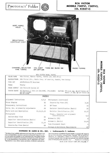
THE COOPERATION OF THE fcRECEIVER MAKES IT POSSIBLE TO5U46® «" ® RECW.E1®4f* 4I M-Y BLK.-BRN.*-l BLUEA PHOTOFACT STANDARD NOTATION SCHEMA©Howard W. <strong>Sams</strong> & Co., Inc. 1949PAGE 2
THE MANUFACTURER OF THISiLE TO BRING YOU THIS SERVICE
BIAS CLAMPER®6ATBoamto
*7.•;---'» \•CHASSIS BOTTOM VIEW-TRANS., INDUCTOPAGE 4
CTOR AND ALIGNMENT IDENTIFICATIONPAGE 9
O mCn\' s' \\O; "\/ ^\BOTTOM VIEWoHOBAGS]XCT\3Rt3 VIDCOIFR. OUT PUTTUBE PLACEMENT CHART'LAIOCZ siaaowTOP VIEW
1.2.3.1.2.4.5.6.7.10.12..05MFD.05MFDTV ALIGNMENT INSTRUCTIONSALIGNMENT INSTRUCTIONS-READ CAREFULLY BEFORE ATTEMPTING ALIGNMENTIf receiver Is to be aligned with picture tube removed, it Is recommended to also remove the 6SN7GT (V15) horizontaloscillator tube to eliminate high voltage shock hazard.When complete alignment Is to be performed, It can most conveniently be done In the order outlined;SOUND IF ALIGNMENT USING AM SIGNAL GENERATOR AND VTVMDUMMYSIGNALSIGNALGENERATOR GENERATOR CHANNELCONNECTANTENNAVTVMADJUSTREMARKSCOUPLINGFREQUENCY.05MFD High side to pin 113A1.A2 Detune Al. Adjust A2 for maximum deflection.(Grid) of 6AU6 (V10)Low side to chassis,nHigh side to pin 1(Grid) of 6BA6 (V9).Low side to chassis.21.25MC(Uranod.)""nDC Probe thru 1Meg to Polnt^Common to chassis.DC Probe thru 1Meg to Point
13.14,15.16.17.18.DUMMYANTENNAnSWEEPGENERATORCOUPLINGTV ALIGNMENT INSTRUCTIONS CCONTJSWEEPGENERATORFREQUENCY85MC(10MCSweep)79MC(10MCSweep)69MC(10MCSweep)63MC(10MCSweep)57MC(10MCSweep)MARKERGENERATORFREQUENCY83.25MC87.75MC77.25MC81.75MC67.25MC71.75MC31.25MC65.75MC55.25MCCHANNEL65432CONNECTSCOPEADJUSTA16,A17A18,A1£59.75MCOSCILLATOR ALIGNMENTReplace oscillator tube (V3).Set fine tuning control to the raid-point of Its tuning range.The sound IF system must be accurately aligned before starting the oscillator alignment.DUMMYSIGNALSIGNALANTENNAGENERATOR GENERATOR CHANNEL CONNECTCOUPLINGFREQUENCYVTVMADJUSTTwo 120S Across antenna terminalswith 120SMeg to Point 215.75MC 13 DC Probe thru 1 A20,A21carbonres . resistor In eachCommon to chassis.lead.slug pairstinn209.75MC203. 75MC197.75MC191.75MO185.75MC179.75MC87.75MC81.75MC71.75MC65.75MC59.75MO12111098765432A22A23A24A25A26A27A28A29A30A31A32ASSREMARKSAdjust for approximately flattopped response curve as per Fig 4.Markers must be above <strong>70</strong>%. Keepslug pairs In approximately samerelative position.Check to see that response Is asabove. Slight readjustment of A16,A17,A18,A19 may be necessary toobtain optimum performance on alllow band channels.REMARKSAdjust for zero reading. A positive andnegative reading will be obtained oneither side of the correct setting. KeepIn same relative position.Adjust for zero reading. A positive andnegative reading will be obtained on eitherside of the correct setting.Adjust for zero reading. A positive andnegative reading will be obtained on eitherside of the correct setting. Keep slugpairs In same relative position.Adjust for zero reading. A positive andnegative reading will be obtained on eitherside of the correct setting.WAVE TRAP ADJUSTMENTWave traps A34 and ASS are used for specific types of Interference and their alignment will depend upon the typeencountered. With the receiver t uned to the channel having the Interference set fine tuning control until InterferenceIs at maximum. Adjust A34 and A35 for minimum Interference In the picture and sound. Keeping the cores at approximatelythe same relative position. Turn one core 1/2 turn, adjust the other for minimum Interference.om3*38BSQtoFIG. I FIG. 2FIG.3 FIG. 4PAGE?
20 .Q1MFD21 .01MFD1920 .01MFD2324 .01MFD26 200MMFDRADIO ALIGNMENT INSTRUCTIONSALIGNMENT INSTRUCTIONS— READ CAREFULLY BEFORE ATTEMPTING ALIGNMENTWhen complete receiver alignment Is to be performed align the FM IF Amp. before aligning AM IF Amps.To set pointer turn tuning cap fully closed and set pointer to last reference mark at low frequency end of dial.Volume control should be at maximum position.obtain an output reading.Output of signal generator should be no higher than necessary toUse an Insulated alignment screwdriver for adjusting.FM IF ALIGNMENT USING AM SIGNAL GENERATOR AND VTVMConnect two matched 100K2 (t 1%) resistors In series from Polntdj^to chassis.Is alignment Pointas shown on the schematic.SIGNALSIGNAL BANDDUMMYGENERATOR GENERATOR SWITCHANTENNACOUPLINGFREQUENCY POS.19 .01MFD High side to pin 1 10.7MC FM(Grid) Of 6AU6 (V23). (Unmod. ) (Ext.Low side to chassis.clockwise.).01MFDAcross antenna terminals.10.7M3RADIODIALSETTINGTuning gangfully closediiCONNECTVTVMDO Probe toPolnt Commonto Pointf>DC Probe toPoint^ Commonto chassis.•Use frequency modulated signal with 60^, modulation and 450KO sweep.horizontal deflection.SIGNALCONNECTDUMMYGENERATORANTENNASCOPECOUPLINGAcross antenna terminals.DUMMYSIGNALANTENNAGENERATORCOUPLING22 Two 1202Across antenna terminalswith 120Scarbonres. resistor in eachlead.SIGNALGENERATORFREQUENCY10.7MC(450KCSweep )SIGNALGENERATORFREQUENCY106MC90MCBANDSWITCHPOS.FMBANDSWITCHPOS.FMRADIODIALSETTINGTuning gangfully closed;M RF ALIGNMEURADIODIALSETTING106MC(5 3/4" toright ofleft handcalibrationmark at lowfreq. end ofdial backplate).9 CMC(1 1/8" toright ofthereferencepoint listedabove) .Vert. Amp. toPoint\/>. Lowside to chassis.Vert. AmP- toPoint^p Lowside to chassis.CONNECTVTVMDC Probe toPoint ^pi Commonto chassis.ADJUSTA36A37A38,A39,A40,A41The Junction of these two resistors'REMARKSAdjust for maximum deflection.Adjust for zero reading. A positiveand negative reading will beobtained on either side of thecorrect setting. Repeat steps 19and 20 If A37 required much adjustment.Adjust for maximum deflection.Alternately load the primary andsecondary windings of the IFtransformers with 680ffl while theopposite side of the same transformeris being adjusted.Use 120% sawtooth voltage In scope forADJUSTA36,ASS,A39,A40,A41A37ADJUSTA42,A43A44,A45REMARKSDisconnect stabilizer C7. Adjustfor maximum amplitude and symmetryas per Fig 5.Reconnect stabilizer cap C7. AdjustA37 so crossover point occurs atcenter of pattern as per Fig 6.Slightly retouch A36 for maximumamplitude and stralghtness ofcrossover lines. Continue withstep 22.REMARKSAdjust for maximum deflection.25 200MMFD High side to terminal2 of antenna terminalstrip. Low side tochassis.1400KC600KCFM IF alignment must be complete before starting AM alignment.Volume control should be at majcimum position. Output of signal generator should be no higher than necessary toobtain an output reading. Use an insulated alignment screwdriver for adjusting.DUMMYSIGNALSIGNAL BAND RADIOANTENNAGENERATOR GENERATOR SWITCH DIALOUTPUTCOUPLINGFREQUENCY POS. SETTINGMETERADJUSTREMARKSHigh side to pin 7 4S5KC AM Tuning gang Across voice A46,(Grid) of 6BE6 (V21). (40CA, (3 pos-fully closed coilA47,Low side to chassis. Mod.)A48,A49itionsclockwise)1400KC(5 15/16" tothe right ofleft handcalibrationmark at lowfreq. end ofdial backplate).600KO(1 1/4" tothe right ofthereferencepoint listedabove.A50,A51A52,ASSiiAdjust for maximum output. Alternatelyload the primary and secondarywindings of the AM IF transformerswith 47KS2 while the oppositeside of the same transformeris being aligned.Adjust for maximum output.Adjust for maximum output. Repeatsteps 24 and 25.FIG.5 FIG. 6PAGE 8
RF TUNER-RIGHT SIDERF TUNER-LEFT SIDEPAGE 10
PAGE 18CHASSIS BOTTOM VIEW-CAI
APACITOR IDENTIFICATIONPAGE I
Id-MBA IAIO11O8 SISSVHOZl
RESISTOR IDENTIFICATIONPAGE 17
ITEMNo.VIV2V3V4V5V6V7V8V9V10 LimlterVI 1 DiscriminatorV12VISV14V15V16V17V18V19V20V21V22V23V24V25V26V27V28.V29V30TEMNo.CIABC2ABC03ABC4ABC5ABCC6ABC07C809CIOOil012CISC14015016017C18019C20C21022C23024C25026C2<strong>70</strong>28C29030031C32CSS034035C36C37CSS039C40C41C42043044C45046047C48C49S50051C52USERF Amp.MixerOscillator1st Video IF Amp2nd Video IF AmpSrd Video IF AmpVideo Det.-ClamperVideo Amp.1st Sound IFAmp .Bias ClamperSync. Amp. -Sync.Sep.Vert. Os c. andDlsch.-Vert.OutputHor. Osc.-AFOHor. OutputDamperHV RectifierLV RectifierFM Conv.AM Conv.1st IF Amp.2nd IF Amp.Ratio Det.Det.-AVC-PhaseInv.AF Amp.Power OutputPower OutputRectifierPicture TubeRATINGCAP. VOLT4010404013080102501000301030303040510102<strong>70</strong>2<strong>70</strong>1.51.5150015002.24.7.681500221500621500104.74.72<strong>70</strong>.25150015002<strong>70</strong>15001500562<strong>70</strong>7510015002<strong>70</strong>10.05.05.2515001500.01150015002<strong>70</strong>.05100.39045035045015050450450106350400250450350255050020010001000100050040040020040010004005001000PARTS LIST AND DESCRIPTIONSTUBES (SYLVANIA or Equivalent)REPLACEMENT DATA RMARCASTANDARD BASEPART No. REPLACEMENT TYPE6J66J67BF6J66J67BF6J66J67BF6AGS6AG5 7BD6AQ56AG5 7BD6AG56AG5 7BD6AL512AU76BA66AU66ALb6AT66SN7GT6SN7GT6SN7GT6BG6G5V4G1B3GT5U4G6BE66BE66BA66AU66AL56SQ76SQ76K6GT6K6GT5Y3GT10BP46AL512AU76BA66AU66AL56AT66SN7GT6SN7GT6SN7GT6BG6G5V4G1B3GT5U4G6BE66BE66BA66AU66AL56SQ76SQ76K6GT6K6GT5Y3GT10BP46BT9A7BK7BK6BT7BTBED8BD8BD5BT5L3C5T7CH7CH7BK7BK6BT8Q80,7S7S5TNOTESCAPACITORSCapacity values given in the rating column are in mfd. for Electrolyticand Paper Capacitors, and in mmfd. for Mica and Ceramic Capacitors.RCAPART No.717827178171780714367273672052721217154071540715007150071501715017150S71520715047150133101715017150145466715207152065401<strong>70</strong>61871501715017309171501715017309145469715017309172615<strong>70</strong>615<strong>70</strong>615<strong>70</strong>6187150171501<strong>70</strong>610715017150173091<strong>70</strong>6153962873094AEROVOXPART No.AF82J2HIAF88J26BAF164JAF50R200SAF862J4A*AF66J4APRS150/41468-00025P488-251467-00151467-00151468-000251467-00151467-00151468-000251469-0000751468-00011467-00151468-000251468-00001P488-05P488-05P488-251467-00151467-0015P488-011467-00151467-00151468-00025P488-051468-00011468-0004REPLACEMENT DATACORNELL-DUBILIERPART No.UP7BJ920UP9CJ887UP9BJ857UP7BJ 808UP8CJ898UP2245COBBR5-50T5W5T25GT2P251W5D151W5D155W5T251W5D151W5D155W5T255W5T11W5D155W5T255W5Q1GT4S5GT4S5GT2P251W5D151W5D15GT4S11W5D151W5D155W5T25GT4S55W5T15W5T4ERIEPART No.NPOK-10NPOK-10GP2K-250GP2K-250NPOK-1.5NPOK-1.5GP2L-0015GP2L-0015GP2L-0015GP2L-0015GP2L-0015GP1K-10GP2K-250GP2L-0015GP2L-0015GP2K-250GP2L-0015GP2L-0015GP2K-250NPOM-75GP1K-100GP2L-0015GP2K-250GP1K-10GP2L-0015GP2L-0015GP2-335-01GP2L-0015GP2L-0015GP2K-250OP1K-100SPRAGUEPART No.TVL-69D-12647TVL-47TVL-66TVL-56r EL330I TVA-6TVA-131FM-325TC-21FM-8151FM-2151FM-3251FM-2151FM-2151FM-3251FM-311FM-2151FM-325Jfi-41TM-15TM-15TC-21FM-2151FM-215TM-111FM-2151FM-2151FM-325TM-151FM-S11FM-34IDENTIFICATION CODESANDINSTALLATION NOTESFilterVert. Output Dec.FilterFilterVert. Output Oath. Byp.FilterVert. Osc. DecouplingHor. Cent. Cont. Byp.Vert. Cent. Cont. Byp.FilterFilterDecouplingFilterFilterOutput Cath. BypassStabilizing Cap.Fixed Trimmer *Fixed Trimmer *RF CouplingNeutralizingBias FilterRF Plate DecouplingRF CouplingIInMuFilament BypassFixed TrimmerConv. Plate Dec.Fixed TrimmerOsc. Plate DecouplingOsc. FeedbackIF CouplingBias FilterBias Filter1st V. IF DecouplingIF CouplingBias Filter2nd V. IF DecouplingFixed Trimmer »IF CouplingFixed TrimmerSrd V. IF Cath. BypassSrd V. IF DecouplingIF CouplingV. Diode FilterVideo CouplingVideo CouplingPic. Tube Cath. Dec.1st S. IF Cath. Bypass1st S. IF DecouplingLlmiter Grid FilterLimlter Screen BypassLimlter Plate Dec.RF BypassVideo CouplingSync. CouplingSync. Amp. Cath. BypassPAGE 13o omO
ITEMNo.053C54C55C56C57C58CCC6061C62CC6364C65C66C 37CCCC 3839<strong>70</strong>71C 72CC 7374C75C 76C 77C 78CC 30C31CCCCCCCC3233343536373809C90C31C 32C33C94C35C96C 37CC 3839Cl 00Cl 31C102C103Cl 34C105C106Cl 37Cl 38Cl 39Cl LOcmCl \S.C113ITEMNo.R1ABR2ABR2ABR3ABR4R5R6R7R8ABITEMNo.R9RIORllR12R13R14R1SR16R17R18R19R20R21RATINGCAP. VOLT.002.005.0054<strong>70</strong>0.1.25120120.0025.25.02180220039047.25.05.035.1.05500.01.01°7330.0110005612012056390.01.0547.005.005.005.005.005.01330330.005.005.005.005.005.015.015.003.003.01120.01.005.02.0035.0035.00350 34« 320 340 340020 340 340 340050 350020 320( 320( 320 320 320020040C400400RCAPART No.71£ 2471( 1471f 1471£ 2472£ 7571E 2571E 5139C)4271E 5371553 .72' 19071! >5371; )537192572" 937279372' 19072' 19072' 19072' 19072' 190721207212072E737257371S25716 1471S25724 907oe 11<strong>70</strong>646AEROVOXPART No.P688 -0021468- 00015GPi K-15040C)20C)40CP488- 01P688- 005P488- 02GPi -335-01GPi M-005Audio CouplingntiII t!1000P1088-0033Output Plate BypassII II NIOC 0 7oe 46 F108E -0033600 72874 P6 88-003Line Filter* Not used In all models.t When either item C95 or C96 are replaced, replace both with capacitors of equal value.4- Omit bypass section.# Omit one 10MFDCAPACITORS CCONT.JREPLACEMENT DATACORNELL- ERIEDUBILIER PART No.PART No.GT6D2 GP2M-002GT6D5 GP, 2M-005GT6D5 GP, JM-005GT2P25GT6D2GT2P25GT4S2GT4S55W5T155W5Q55R5T4GT4S1GT2S55W5Q5GT6D5GT6D5GT6D5GT6D5GT6D5GT4S15W5T35W5T3GT6D5GT6D5GT6D5GT6D5GT6D5GT6S15GT6S1SGT6D3GT6D3GT4S15W5T15GT4S1GT6D5GT4S2GT16D3GT16D3GT6D3GP, 2M-002op:41C -500GP3K-25GPi K-300GPi -335-01GPi L-001GPI K-50QPi K-150GP] K-50GPi,-335-01GP, K-50GPi,M-005GP2M-005GPi M-005GPi,M-005GPi,M-005GPi,-335-01GPi,K-300GP2K-300GPi,M-005GPi,M-005GPi,M-005GPi,M-005GPt M-005600 <strong>70</strong>60140 3 7oe50640 3 <strong>70</strong>f)065CX372! ;2410 30 73 L0120 3 <strong>70</strong>( i!850 39 33050 3 39 33040 3 <strong>70</strong> 3221500 7280920 3 <strong>70</strong> 31840 3 <strong>70</strong> 3111000 73102500 39660IOC 0 73C 9450C 39£ 2020C)<strong>70</strong>f 1860C)<strong>70</strong>f 3660C 731 00IOC)07310140C) <strong>70</strong>C- 15100 00 714 50400 717<strong>70</strong>40C)71" <strong>70</strong>72E <strong>70</strong>sex)72n 9340C)71£ 25P688-002P688--005P688--0051084 -1P488--25P488--25P488 -021469- 0004 5R5T41468- 00005 5W5Q5P488- 25 GT2P25P688- 05 GT6S51084- 1P488- 05P488-01 GT4S1P488- 01 GT4S11468-C 00025 5W5Q251468- 00035 5W5T4P488- 01 GT4S11468- 001 1W5D11468- 00005 5W5451468- 000151468- 000051469--0004P483- 01P288- 051468- 00005P688- 005P688-005P688- 005P688- 005P688- 005P488-011468- 00031468-0003P688- 005P688- 005P688- 005P688- 005P688- 005P288-015P288-015P688- 003P688-003P48S-01RATINGRESIST-ANCE50K21 Meg.lOKffl500K210K2500K250002Shaft2.5 Meg202202225021.5 MegSwitch}section.Tin AWATTS PART No.4 ] 72734\}71784 *J•J4221 44RATINGRESISTANCE150215024<strong>70</strong>024<strong>70</strong>021000210K21 Meg.10002100K2100K247ffl4<strong>70</strong>02150273193 §71441Not Rea.71'14071443714437273572851Not Req.WATTS\444K-50GPi M-003GP2M-003GP2-335-01CONTROLSREPLACEMENT DATA|D/~PART No.CJ11-114Qll-S,37W-20X10W-20X10Q18-139XX76-1PART No.9<strong>70</strong>111-249<strong>70</strong>111-189<strong>70</strong>111-18M-19-SNot. Req.43-20CT43-20P-10-2500T-95SW-A§ Used only when Decal. Part 173196 or 73197 is used.* Used only when Dseal. Part #73028 or 73045 is used.RESISTORSREPLACEMENT DATARCAPART No.IRCPART No.SPRAGUEPART No.TM-22TM-25TM-25TC-2TM-22TC-2TM-12MS -341FM-45TC-2TM-15TM-15TM-11TM-11MS -4251FM-335TM-111FM-211FM-451FM-3151FM-45MS-34TM-11TM-151FM-45TM-25TM-25TM-25TM-25TM-25TM-111FM-3251FM-325TM-25TM-25TM-25TM-25TM-25TM-23TM-23TM-111FM-315TM-11TM-25TM-12MB-23MB-23TM-23Horlz. Hold ControlVert. Hold ControlIDENTIFICATION CODESANDINSTALLATION NOTESIntegrator Net.iiiiiitiVert. Osc. Grid Cap.Vert. DischargeVert. Sweep CouplingHor. Sync. CouplingVoltage DividerHor. Sync. CouplingAFC FeedbackAFC Filter" "Hor. Osc. Grid Cap..Hor, DischargeHor. Sweep CouplingVoltage Divider *Hor. Output Cath. Byp.Hor. Output Screen Byp.Damper FilteriinAFC Plate BypassHV FilterLine FilteriiiiOsc. Grid Cap.FM Osc. Anode BypassFM Osc. Plate Dec.Voltage Divider *Ant. CouplingFixed TrimmerRF CouplingOsc. Grid Cap.Fixed PadderAM Osc. Anode BypassAVC FilterAM Conv. Fll. Bypass1st IF Screen Bypass1st IF Decoupling2nd IF Cath. Bypass2nd IF Screen Bypass2nd IF Plate Dec.RF BypassDiode Load Cap. T" " " TRF Bypassn nDe-emphasisAVC FilterAudio CouplingTone CompensationTone CompensationHnnnAudio CouplingAF Plate BypassINSTALLATION NOTES,„ , rrmf.pntrlp)(Dual Concentric)Contrast Control (Dual Concentrlc)Brightness Control *Contract Control ninal fnnrpntri r]Brightness Control (Dual Wncentric)Vert. Linearity Control , „ t ,Attach to R3A Per Instructions
PARTS LIST AND DESCRIPTIONS (Continued)RESISTORS CCONTOIDENTIFICATION CODESANDINSTALLATION NOTESntegrator Net.ert. Osc. Grid Cap.ert. Dischargeert. Sweep Coupling.or. Sync. Couplingoltage Divideror. Sync. CouplingFC FeedbackFC Filterlor. Osc. Grid Cap..or. Dischargeor. Sweep Couplingoltage Divider «or„ Output Cath. Byp.or. Output Screen Byp.amper FilterFC Plate BypassV FilterineiiFilteriisc. Grid Cap.Osc. Anode BypassM Osc. Plate Dec.oltage Divider *nt. Couplingixed TrimmerF Couplingsc. Grid Cap.ixed PadderM Osc. Anode Bypassvc FilterM Conv. Fil. Bypassst IF Screen Bypassst IF Decouplingnd IF Cath. Bypassnd IF Screen Bypassnd IF Plate Dec.F Bypasslode Load Cap. T11 TF Bypasse-emphasisVC Filterudio Couplingone Compensationone Compensationudlo CouplingF Plate Bypassudio Couplingutput Plateine Filter.pacitors of equal value.ALLATION NOTESIL(Dual Concentric)(Dual Concentric)(Dual Concentric)"Suctions
TIONS (Continued)JTJNetworkideo IF Grid'ideo IF Cathode'ideo IF DecouplingIdeo IF Grid'ideo IF CathodeIdeo IF Decoupling.ge Divider'ideo IF Grid'ideo IF CathodeIdeo IF Plateideo IF DecouplingDet. Diode LoadAmp. GridAmp. PlateOutput GridOutput CathodeOutput PlateIDENTIFICATION CODESge Divideround IF Cathodeound IF Decouplingound IF Gridound IF Screen Decouplingound IF Plate DecouplingFilament Wire WoundDiode LoadAmp. GridAmp. PlateSep. GridSep. CathoderatorOsc. GridOsc. Platege DividerOutput GridOutput CathodePeakingr. AFC Grid. AFC Cathode" " Temp. Comp.;. AFC Plate;. AFC Filter Network.ge Divideriack-ge Divider Temp. Comp.. Osc. Grid Carbon Film Type. Osc. Transformer Shunt. Osc. Plateitic Suppressor. Output Grid. Output Cathode. Output Screenackrack,ct. Filament Wire WoundIterCoil ShuntNetwork Wire WoundrWire WoundNetwork wire Wound^;e Divider Wire Wounder Wire WoundNetwork See Notet. Isolationiv. Decouplingc. Gridc. Platec. Platenv. Grid•:. Grid:. Plate'" Cathoder Screenr Decoupling3tworkLoad1 IF Cathode•1 IF Screen Decoupling1 IF Plate Decoupling;ing)hasis;ingDet. Diode Loaditworkid AVClompensationInv. GridInv. Plated80%20%80%20%20%20*2058,20565%5%20%20%20*205620%5%20%20%20%5%20%20%20%20%20%20%5%20%20%20%ITEMNo.R131R132ITEMNo.T1ABT2ITEMNo.T3T4T5RATINGRESISTANCE I WATTS2<strong>70</strong>K24<strong>70</strong>KB5602REPLACEMENT DATARCAPAST No.72865RESISTORS CCONT.JIRCPART No.BTS-2<strong>70</strong>KBTS-4<strong>70</strong>KBTS-8200BTS-4<strong>70</strong>KBW-2-S60AF PlateOutput Grid3300233002Note. Used only when Ion trap magnet coil Is not used.PRI.117VAC® 1.84A117VAG® .60ASEC. 1720VCT© .24ADCSEC. 46 .3VAC® 7.1A6BOVCT© .073ADCRATINGSEC. 25VACg>3ASEC. »6.3VAC© .6A5VAC® 2ASEC. 35VACS)2A6 .3VAC©3.9AIDENTIFICATION CODESOutput Cathode Wire WoundParasitic SuppressorFilterTRANSFORMER (POWER)RCAPART No.7177273150 4- *71975STANCORPART No.P-8153P-6012 f TtREPLACEMENT DATATT Add series resistor to reduce plate voltage.I Drill new mounting holes,44 50% transformer.TRANSFORMER (SWEEP CIRCUITS)T6T7ABT8ITEMNo.T9ITEMNo.SP1SP2ITEMNo.LIITEMNo.L2L3L4L5L6L7L8L9L10LllL12L13RATINGDC RESISTANCEPRI. SEC.1172 Tap® 85216524102 Tap® 1<strong>70</strong>2590214863225SS2IMPEDANCEPRI. SEC.12K2CT2.62FIELD RES.PMCONE DIA.12"TOTALDIRECTCURRENT.240AUSE13102SEC. 110. 6SiTapS> .62SEC. 20272RATINGRATINGRCAPART No.727<strong>70</strong>7177571416717747142073233DC RES.PRI. SEC.6302CTV. C. IMP.2.62V. C. DIA.1"RATINGSD. C.RESISTANCE642Ant. InputInterferenceTrapInterferenceTrapFil. Chk.Mixer GridTrap1st VideoIF andSound Trap2nd Video IF3rd Video IFSound Trap4th Video IFPeakingPeakingPRI.020202OffiOS!.22.12.IS02.122.2ffi62.22DC RES.REPLACEMENT DATASTANCORPART No.A-8121A-8117A-8115DY-1FC-10CHICAGOPART No.TBO-1TFB-1TSO-1MERITPART No.A-40QOA-3035TRANSFORMER (AUDIO OUTPUT)REPLACEMENT DATARCAPART No.37899RCAPART No.71961STANCORPART No.A-3823SPEAKERREPLACEMENT DATAJENSENPART No.ST-102 §MOD.P12-SINDUCTANCE RCA10 CURRENT1000 f} PART No.2.5Henries 719<strong>70</strong>02OSSEC.CHICAGOPART No.RO-111QUAMPART No.12A4AFILTER CHOKEREPLACEMENT DATASTANCORPART No.C-2325COILS (RF-IF)REPLACEMENT DATARCAPART No.715077150571506728117142673<strong>70</strong>8717787142671793MEISSNERPART No.MERITPART No.A-2901CHICAGOPART No.TR-4225Part of Tunern n nii n nII M Itn n iiCHICAGOPART No.TP-392PH-<strong>70</strong>B t ttMERITPART No.P-3059P-2951 tNOTESHor. Osc. CoilVert. Block. Osc. TransHor . Output Trans .Vert. Output Trans.Hor. Deflection CollVert. Deflection CoilFocus CollINSTALLATION NOTESNOTES§ Replace output transformerto match 6-82 voice coil.MERITPART No.C-2991NOTESINSTALLATIONNOTESIncludes 62MMF capacitor. Part of tuner.Trap winding not used in all receivers.Includes 56MMF capacitor.Includes 75MMF capacitor.36 Microhenries180 Microhenries. Wound on 39KS2 resistorNot used in all receivers.omN§iK)PAGE 15
ITEMNo.L14L15LieL17LIBL19L20L21L22L23L24L25L26L27L28129ISOITEMNo.MlM2M3M4TEMNo.MSM6M7MSM9moUSEPeakingPeakingPeakingSound IFDisc. TransWidth Cont.Hor. LinearityFM Ant.FM Osc.AM Ant.AM Osc.FM 1st IFAM 1st IFFM 2nd IFAM 2nd IFRatio Det.Trans .Fll. Chk.PARTS LIST AND DESCRIPTIONS (Continued)BASE TYPEBayonetBayonetBayonetBayonetPRI.4.5S22.2S4.52OfflOffl02362OfflOffl26ffl4ffl.521221.2982.12OfflPART NAMEBand SwitchTone SwitchFuseTuning CapIon TrapTunerSafety GlassDial ScaleDial ScaleKnobKnobKnobKnobKnobKnobKnobKnobKnobDC RES.020202SEC.1.52.82122.5282,12VOLTS7.57.57.57.5AMPS..2.2.2.2COILS CRF-IF)CONT.REPLACEMENT DATARCAPART No.7152971793715297142471427714397144972335723367207172333728877162572888716317288972574BEADCOLORWhiteWhiteWhiteWhiteRCAPART No.72852716037205971792KRK2B-173027730<strong>70</strong>72682718217280071533715347153571536725657256672567MEISSNERPART No.14-106016-665816-6660DIAL LIGHTSREPLACEMENT DATAROAPART No.11765117651176511765MISCELLANEOUS iIncludes TV Power SwitchNot used in all sets26-568MMF, 13-368MMF W/TElecto-MagnetNOTES120 Microhenries. Wound on 22K2 resistor.36 Microhenries.120 MicrohenriesIncludes 10MMF capacitor and 33MMF cap.Includes 2-56MMF capacitor and 47MMF cap.Type #51Type *51Type 151Type #51NOTESNOTESFor model 730TV1For model 730TV2For radio tuning, band switch, off-volume, and toneswitch for walnut or mahongany Instruments.For radio tuning, band switch, off-volume and toneswitch for toasted mahogany instruments.For fine tuning for walnut or mahogany instruments.For station selector for walnut or mahoganyinstruments .For brightness and vertical hold for walnut ormahogany instruments .For contrast or horizontal hold for walnut or mahoganyInstruments.For brightness and vertical hold for toasted mahoganyinstruments .For contrast and Hor. hold for toasted mahoganyinstruments .For fine tuning for toasted mahogany instruments.DISASSEMBLY INSTRUCTIONS1. Remove 3 push-on type knobs from TV controls.2. Remove 4 push-on type knobs from receiver controls.3. Remove 9 screws holding rear cover.4. Remove picture tube base socket and Ion trap.5. Remove HV cap from picture tube.6. Remove 2 phlllips-head screws from upper corners of picture tube front plate. Remove front plate.7. Loosen 4 screws holding clamps at large end of picture tube. Remove tube, slide forward.8. Remove TV power plug from rear of receiver chassis.9. Remove TV audio plug from rear of receiver chassis.10. Remove TV antenna plug from rear of receiver chassis.11. Remove 7 hex head bolts holding TV chassis.12. Remove TV chassis.13. Remove speaker plug at speaker.14. Remove phono audio plug from rear of receiver chassis.15. Remove receiver antenna plug from rear of receiver chassis.16. Disconnect phono power plug.17. Remove panel lamp from Inside bottom front center of cabinet.18. Remove panel lamp from phono section.19. Remove two hex head bolts from rear of receiver mounting board.20. Remove two hex nuts holding receiver chassis to mounting board. Remove hooked studs by pushing up and turn21. Remove receiver chassis.22. Remove four hex nuts holding speaker.23. Remove speaker.PAGE 16
A PHOTOFACT STANDARD NOTATION SCHEMATIC©Howard W. <strong>Sams</strong> & Co., Inc. 1949PAGE 26
@6AL56SQ76K6GTPOWER OUTPUT• 330•MMF820.Dji)®.10 K«g =•®" ^1 5 > + MFD >rtlTftrTHE COOPERATION OF THE MANUFACTURER OF THISRECEIVER MAKES IT POSSIBLE TO BRING YOU THIS SERVICEA r~a ^fSW. ON OBAND SW.LI ®i\SW.ON V—^-T"-,o^ VOLUMET CONTROLPAGE 19
nru oRADIO CHASSIS-BOTTOM VIEW-CAPACITOR IDENTIFICATION
IhJLnRADIO CHASSIS-BOTTOM VIEW-RESISTOR IDENTIFICATION'CA10CZ 'lAlOeZ S1300WM01DIA V32I
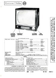
I mroAM-FM TUNERV20, V21, V22, V23,V24, V291st SOUND IF V9LMITER VI0AF AMP V26PHASE INV. 1/2 V25POWER OUTPUT V27POWER OUTPUT V281st VIDEO IF2nd VIDEO IF3rd VIDEO IFSYNC. AMP, 1/2 V13SYNC. CLAMPER1/2 V 7SYNC. SEP 1/2 V13 VERT. OUTPUT1/2 V14HOR. AFC 1/2 V15L.V. RECT V19 RCA 730TV1BLOCK DIAGRAM'CAIOCZ 'LAIOCZ siaaowVDU
RADIO CHASSIS-TOP VIEW
mro RADIO CHASSIS-BOTTOM VIEW'LAIOCZ siaaowiJOlDIA V3M
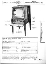
HORIZ. LIN.VERT. LIN.HORIZ. LOCKHEIGHTHORIZ, DRIVEVERT. CENT.HORIZ. FREO.CABINET-REAR VIEWHORIZONTAL OSCILLATOR AND LINEARITY ADJUSTMENTSHORIZONTAL OSCILLATOR ALIGNMENT CHECK:Tune In test pattern and turn horizontal hold controlto extreme counter-clockwise position. Picture should remainIn synchronization. Turn channel switch to anotherchannel and then back to the original channel. Normally,the picture should be out of synchronization. Turn thecontrol clockwise and the picture should slowly begin tosynchronize and finally lock-In, This should occur whenthe control Is approximately 90" from the extreme counterclockwiseposition. The picture should remain In synchronizationfor another 90' In the clockwise direction ofthe control. At the extreme clockwise position the pictureshould again drop out of synchronization and 3i to 4ibars should be seen sloping downard to the right. If thereceiver falls to hold synchronization during this checkwith the hold control at the extreme counter-clockwiseposition or falls to hold.synchronization for at least60* In the clockwise direction from the point when Itdrops Into "sync" It will be necessary to align the horizontaloscillator circuit as follows:(A) HORIZONTAL OSCILLATOR ALIGNMENT:Turn horizontal hold control to extreme clockwiseposition. Tune in test pattern and adjust trimmer Bl untilpicture is out of sync, and shown 3£ to 4i bars slopingdownward to the right. If the trimmer has Insufficientrange, set it to its mid-position (one turn from tight)and adjust slug B2 until bars appear.PAGE 24(B) HORIZONTAL LOCKING ALIGNMENT:Turn the horizontal hold control to full counter-clockwiseposition.original again.Switch to another channel and back to theSlowly turn horizontal hold control clockwise and notethe least number of diagonal bars present Just before picturesyncs.If more than 4i bars are present Just beforepicture sync, adjust "horizontal lock" trimmer B3 slightlyclockwise.If less than 3i bars are present adjust B3 slightlycounter-clockwise and switch channel selector to anotherchannel and back again. Recount bars present at the "lock-In" point. Repeat this procedure until 3i to 4£ bars arepresent.Repeat Steps (A) & (B) until conditions exist as outlinedunder "Horizontal Oscillator Alignment Check".WIDTH, DRIVE & HORIZONTAL LINEARITY ADJUSTMENTS:Turn width control B4 to maximum clockwise position.Adjust "horizontal drive" trimmer B5 for maximum brightnessand linearity. Adjust horizontal linearity B6 for bestlinearity In the right half of the picture.control until picture fills the mask.HEIGHT & VERTICAL LINEARITY ADJUSTMENTS:Readjust widthAdjust the height control until picture fills maskvertically. Adjust the vertical linearity control until thetest pattern is symmetrical from top to bottom.Due to IntractioB between thes« two controls it Is necessaryto repeat the adjustment. Adjust the vertical centeringcontrol to align the picture with the mask.
IrnroVOLTAGE AND RESISTANCE MEASUREMENTSVOLTAGE READINGS RESISTANCE READINGSItemV 1V 2V 3V4V5V6V7V8V9V 10V 1 1V12V 13V 14V 15V 16V17V18V19tV20V21V224-V23*V24V25V26V27V28V29V30Tube6J66J66J66AG56AG56AG56AL512AU76BA66AU66AL56AT66SN7GT6SN7GT6SN7GT6BG65V4G1B3GT5U4G6BE66BE66BA66AU66AL56SQ76SQ7SK6QT6K6GT5Y3GT10BP4Pin 1145VDC140VDC75 VDC-8.5VDC-8.8VDCOVOV127V DCOV-.5VDCOVOV-.6VDC»-6VDC»OVOVOVOV$-.2VDC5-8.6VDC-.3 VDCOV2.5VDCOVOVOVOVOV140VDCPin 2145VDC140 VDC75VDCOVOV1.3VDC-.2VDC-.5VDCOVOV-.1VDCOV150VDC»72VDC•137VDC•95VDC6.3VAC320VDCPin 36.3VAC6.3VAC6. 3 VAC6.3VAC6.3VAC6.3VACOVOVOVOV6.3VACOVOV• OV•9.2VDC-65VDC320V DC* DO NOT MEASURE.275VDCOVOVOVOV-.1VDC-.2VDC-.3VDCOV6. 3V AC310VDC75VDC» Measured from Pin 3 of V14.* Do Not Measure .OVOVOVOVOV6. 3 VACOVOV310VDC310VDC240 VDCPIN 10290VDCOVOVovovovovPin 46.3VAC6. 3 VAC6. 3V AC6.3VAC1.8VDC6.3VAC-.2VDC»-.lVDC»-31VDCOV260VDC380VAC6.3VAC6.3VAC6.3VAC6.3VACOV-.3VDCOV240VDC240VDC320VACPIN220VDC11Pin 5-8.8VDC-2.2VDC§-4.8VDC145VDC145VDC95VDCOV6.3VAC125VDC140VDCOVOV232VDC»290VDC•137VDC»OVOVOV260VDC250VDC210VDC240VDC-.1VDC-.4VDCOVOVOVOVPIN 12140VDCPin 6-8.9VDC-3.9VDC5-6.4VDC145 VDC145VDC140VDCOV•150VDC125VDC85VDCOV-9VDC9.4VDC»25VDC« 85VDC»OVOV260VDC380VAC130VDC95VDC120VDC150VDCOV105VDC105VDCOVOV320VACOVOVPin 7.3VDCOVOV1.3VDC-.1VDC»OV1.5VDCOV-.1VDCOV6.3VAC6.3VAC6.3VACOVOVOVOVOV.7VDC.8VDC2.9VDC6.3VAC6.3VAC6. 3 VACOVOVPin 8•.7VDCOVOVOV175VDC320VDC275VDCOVOV20VDC20VDC310VDC02*Pin 9ItemV 1V 2V 3V4V 5V 6V7V 8V9.V 10VllV 12V 13V 14V15V16V 17V18V 19V20V21V22V23V24V25V26V27V28V29V306J66J66J6Tube6AG56AG56AG56AL512AU76BA66AU66AL56AT66SN7GT6SN7GT6SN7GT6BG65V4G1B3QT5U4G4-6BE66BE66BA64-6AU6*6AL56S0.76SQ76K6GT6K6GT5Y3GT10BP4Pin 1I6.5K2t2KfflT5.5KS20K212K215K2.2BT4.5KB024<strong>70</strong>KB200KBInf.» 1 Meg.• 1 Meg.• 850K2Inf.Inf.Inf.Inf.22K222KB2.5 Meg.IB920202OB02OB02T1000BPin 2T6.5KS2t2K2t5.5K239B39215024 Meg.1 Meg.OfflOB100K202T15K2»2.3 Meg»1.2 Meg-320KB.12200K2Inf.4.5K20202OfflOB11K210 Meg.10 Meg.02.12800K2t5K21. DC Voltage measurements are at 20,000 4. Line voltage maintained at 1 17 volts for voltohmsper volt; AC Voltage measured at 1,000 age readings,ohms.. . . . 5. Front panels controls set at minimum.2. Pin numbers are counted in a clockwise directionon bottom of socket. 6. Where readings may vary according to the3. Measured values are from socket pin to com- setting of the service controls, both minimummon negative unless otherwise stated. and maximum readings are given..12.18.Iffl.12.12.120202Offl02.1202OS!Pir 3» 02»280K2• 82B200KBInf.Inf.0202oaoa.1202OB1330813002800KBPIN 10-56K2020202020202.12.12.12.12Pin 42.12.124 Meg.2.2 Meg.• 200KS2Inf.*<strong>70</strong>2Inf.6 <strong>70</strong>2.12.12.12.12Offl2.5 MegOBI2K2#2K82502PIN 11t2802'IMOCZ SlldOWUO1DIA VD3Pin 5100K21 Meg.lOOKfflT2KBT2K2T8.5K2OB.12T2.2KBT2KfflOBInf.T300BT2K2-140K2»1 Meg.Inf.Inf.Inf.#3Kffl#2KffliHKB#3K2Inf.2<strong>70</strong>K2Offl480K24<strong>70</strong>K2Inf.PIN 12T10002Pin 6Pin 7Pin 8 Pin 9100K21 Meg.OfflOffl100K2472T2K239fflT2KB39BT2K21502022K2t5.5KB12. 2KBT23K202100KB6.8K2»5Kffl45002«oaInf.T<strong>70</strong>fflInf.660BfLSKffi120KB128KB• 1 Meg.82202100KBInf..12.12.1202Inf.Inf.Inf.024.5 Meg682• 472020202T5.5K2200K2Inf.4.5K202TOP CAP-2002TUP CAP-4508#33K202I2<strong>70</strong>K2I2<strong>70</strong>K28.2K2Inf.260B682Inf..12.12.1202Inf.0202560B5602800K2T Measured From Pin 8 Of V19.» Measured From Pin 3 Of V14.- Measured From Pin 8 Of V17.t Measured From Pin 8 Of V29.