3GPP Broadband Evolution to IMT-Advanced - 4G Americas
3GPP Broadband Evolution to IMT-Advanced - 4G Americas
3GPP Broadband Evolution to IMT-Advanced - 4G Americas
- No tags were found...

Create successful ePaper yourself
Turn your PDF publications into a flip-book with our unique Google optimized e-Paper software.
Quality of service (QoS). By prioritizing traffic, large downloads can occur withlower priority, thus not affecting other active users.Innovative data plans. Creative new data plans influencing consumptionbehavior, including tiered pricing, could make usage affordable for most users, butcould discourage excessive or abusive use.It will take a creative blend of all of the above <strong>to</strong> make the mobile broadband marketsuccessful and <strong>to</strong> enable it <strong>to</strong> exist as a complementary solution <strong>to</strong> wired broadband.Mobile <strong>Broadband</strong> Cost and Capacity TrendsWhile the cost of delivering data with wireless broadband remains higher than withwireline broadband, costs continue <strong>to</strong> decline rapidly. One vendor has calculated that in ablended HSPA/LTE network that costs could go below 1 Euro per gigabyte (GByte) oncepenetration of mobile broadband reaches 40% and usage reaches 2 GByte per month. 5Figure 3: Opera<strong>to</strong>r CAPEX+OPEX Cost <strong>to</strong> Deliver a GByte of Data<strong>3GPP</strong> technologies clearly address proven market needs; hence their overwhelmingsuccess. The <strong>3GPP</strong> roadmap, which anticipates continual performance and capacityimprovements, provides the technical means <strong>to</strong> deliver on proven business models. Asthe applications for mobile broadband continue <strong>to</strong> expand, HSPA, HSPA+, LTE and LTE-<strong>Advanced</strong> will continue <strong>to</strong> provide a competitive platform for <strong>to</strong>morrow’s new businessopportunities.5 Source: Nokia Siemens Networks white paper, “Mobile <strong>Broadband</strong> with HSPA and LTE – Capacity andCost Aspects,” 2010. Refer <strong>to</strong> the white paper for assumptions used.Transition <strong>to</strong> <strong>4G</strong>: <strong>3GPP</strong> <strong>Broadband</strong> <strong>Evolution</strong> <strong>to</strong> <strong>IMT</strong>-<strong>Advanced</strong>, Rysavy Research/3G <strong>Americas</strong>, Aug 2010 Page 11
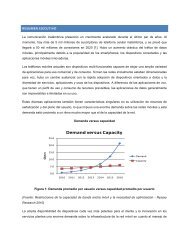
Wireless Data MarketBy June 2010, more than 4.4 billion subscribers were using GSM-HSPA 6 —nearly two-thirds ofthe world’s <strong>to</strong>tal 6.8 billion population. 7 By the end of 2014, the global 3G wireless market isexpected <strong>to</strong> include more than 3.3 billion subscribers of whom 2.7 billion will use <strong>3GPP</strong>technologies, representing 87% market share. 8 Clearly, GSM-HSPA has established globaldominance. Although voice still constitutes most cellular traffic, wireless data worldwide nowcomprises a significant percentage of average revenue per user (ARPU). In the UnitedStates, wireless data exceeds 30% of ARPU on average and is likely <strong>to</strong> reach 35% by the endof 2010. 9This section examines trends and deployment, and then provides market data thatdemonstrates the rapid growth of wireless data.Market TrendsAs stated in a Rysavy Research report for the Cellular Telephone Industries Association(CTIA) on mobile broadband spectrum demand,”We are at a unique and pivotal time inhis<strong>to</strong>ry, in which technology capability, consumer awareness and comfort with emergingwireless technology and industry innovation are converging <strong>to</strong> create mass-marketacceptance of mobile broadband.” 10As data constitutes a rising percentage of <strong>to</strong>tal cellular traffic, it is essential tha<strong>to</strong>pera<strong>to</strong>rs deploy spectrally efficient data technologies that meet cus<strong>to</strong>mer requirementsfor performance—especially because data applications can demand significantly morenetwork resources than traditional voice services. Opera<strong>to</strong>rs have a huge investment inspectrum and in their networks; data services must leverage these investments. It is onlya matter of time before <strong>to</strong>day’s more than 4 billion cellular cus<strong>to</strong>mers start taking fulladvantage of data capabilities. The EDGE/HSPA/LTE evolutionary paths provide datacapabilities that address market needs and deliver ever-higher data throughputs, lowerlatency, and increased spectral efficiency.As a consequence, this rich network and device environment is spawning the availabilityof a wide range of wireless applications and content. Because of its growing size—and itsunassailable potential—application and content developers are making the wirelessmarket a high priority.Based on one leading UMTS-HSPA infrastructure vendor’s statistics, Figure 4 comparesthe rapid growth in wireless data traffic compared <strong>to</strong> voice traffic across multipleopera<strong>to</strong>rs. By the end of 2009, in HSPA coverage areas worldwide, the volume of datatraffic significantly exceeded voice traffic, with data usage actually accelerating.Opera<strong>to</strong>rs that are the most aggressive with mobile broadband services are experiencingdata growth rates even higher than these average values.6 Source: “World Cellular Information Service,” Informa Telecoms & Media, June 2010.7 Source: US Census Bureau, http://www.census.gov/ipc/www/idb/worldpopinfo.html.8 Source: “World Cellular Information Service,” Informa Telecoms & Media, June 20109 Chetan Sharma, US Wireless Data Market Update - Q1 2010.10 Source: Rysavy Research, “Mobile <strong>Broadband</strong> Spectrum Demand,” December 2008.Transition <strong>to</strong> <strong>4G</strong>: <strong>3GPP</strong> <strong>Broadband</strong> <strong>Evolution</strong> <strong>to</strong> <strong>IMT</strong>-<strong>Advanced</strong>, Rysavy Research/3G <strong>Americas</strong>, Aug 2010 Page 12
Figure 4: WCDMA-HSPA Voice and Data Traffic 11Relative Network LoadWCDMA/HSPASpeech + DataWCDMASpeechQ1 Q2 Q3 Q4 Q1 Q2 Q3 Q4 Q1 Q2 Q3 Q42007 2008 2009Over time, data demands are expected <strong>to</strong> grow significantly. Figure 5 shows a projectionby Cisco of global mobile data growth through 2014 in petabytes (million gigabtyes) permonth. Traffic more than doubles every year.11 Based on leading UMTS-HSPA infrastructure vendor statistics.Transition <strong>to</strong> <strong>4G</strong>: <strong>3GPP</strong> <strong>Broadband</strong> <strong>Evolution</strong> <strong>to</strong> <strong>IMT</strong>-<strong>Advanced</strong>, Rysavy Research/3G <strong>Americas</strong>, Aug 2010 Page 13
Opera<strong>to</strong>rs have begun deploying evolved HSPA features. Sixty-five HSPA+ networks arein service in 35 countries as of June 2010. 16 As the technology matures, upgrading <strong>to</strong>HSPA+ will likely represent a minimal investment for opera<strong>to</strong>rs in order <strong>to</strong> significantlyboost network performance.LTE has not only become the preferred choice for opera<strong>to</strong>rs as their next-generationwireless technology, but it has been chosen by public-safety organizations as theirbroadband technology of choice. The Association of Public-Safety CommunicationsOfficials (APCO) and the National Emergency Number Association (NENA) have bothendorsed LTE. 17StatisticsA variety of statistics show the rapid growth in wireless data. Chetan Sharma reportedthat in Q1 2010, the US wireless data market grew 22% over Q1 of 2009 <strong>to</strong> reach $12.5billion in mobile-data service revenues, on track <strong>to</strong> the initial estimate of $54B for 2010.He also states that 62% of US subscribers were using some form of data service. 18Informa projects global mobile revenues <strong>to</strong> exceed $1 trillion in 2013. 19Though most mobile broadband growth <strong>to</strong>day is based on HSPA (with some EV-DO), LTEshould see relatively rapid adoption as it becomes deployed. TeliaSonera launched theworld's first commercial LTE network in Oslo and S<strong>to</strong>ckholm in December 2009, but AsiaPacific and North America will experience the first major wave of LTE rollouts in 2010through 2012. IDATE forecasts growth from 27 million subscribers in 2012 <strong>to</strong> 300 millionby 2015 in five major areas 20 (EU5+Scandinavia, Japan, South Korea, China, USA).According <strong>to</strong> 3G <strong>Americas</strong>, there are more than 100 opera<strong>to</strong>rs that have committed orexpressed intentions <strong>to</strong> commit <strong>to</strong> LTE.International Data Corporation (IDC) forecasts that the U.S. mobile broadband marketwill grow from 6.5 million subscribers in 2009 <strong>to</strong> 30.2 million in 2014, which accounts fora compound annual growth rate (CAGR) of 36.1% over the forecast period. 21From a device perspective, Informa WCIS projected in June 2010 the following sales ratefor WCDMA handsets: 222010: 426 million (34% of global <strong>to</strong>tal)2011: 590 million (43% of global <strong>to</strong>tal)2012: 771 million (52% of global <strong>to</strong>tal)2013: 984 million (62% of global <strong>to</strong>tal)2014: 1.2 billion (70% of global <strong>to</strong>tal)16Source: 3G <strong>Americas</strong>, June, 2010.17 Source: http://www.fiercewireless.com/s<strong>to</strong>ry/public-safety-groups-endorse-lte-broadbandsolution/2009-06-1218 Source: Chetan Sharma, US Wireless Data Market Update - Q1 2010.19 Source: Informa Telecom & Media, January 15, 2010.20 Source: IDATE, June 14, 2010. http://www.idate.org/en/News/-LTE-forecasts-worldwide_642.html21 IDC Says Market for U.S. Mobile <strong>Broadband</strong> About <strong>to</strong> Speed Up, June 15, 201022 Source: “World Cellular Information Service,” Informa Telecoms & Media, June 2010.Transition <strong>to</strong> <strong>4G</strong>: <strong>3GPP</strong> <strong>Broadband</strong> <strong>Evolution</strong> <strong>to</strong> <strong>IMT</strong>-<strong>Advanced</strong>, Rysavy Research/3G <strong>Americas</strong>, Aug 2010 Page 15
It is clear that both EDGE and UMTS/HSPA are dominant wireless technologies. Andpowerful data capabilities and global presence mean these technologies will likelycontinue <strong>to</strong> capture most of the available wireless-data market.Wireless Technology <strong>Evolution</strong>This section discusses 1G <strong>to</strong> <strong>4G</strong> designations, the evolution and migration of wireless-datatechnologies from EDGE <strong>to</strong> LTE, as well as the evolution of underlying wireless approaches.Progress in <strong>3GPP</strong> has occurred in multiple phases, first with EDGE, and then UMTS, followedby <strong>to</strong>day’s enhanced 3G capabilities such as HSPA, HSPA+, and now, LTE, which itself isevolving <strong>to</strong> LTE-<strong>Advanced</strong>. Meanwhile, underlying approaches have evolved from TimeDivision Multiple Access (TDMA) <strong>to</strong> CDMA, and now from CDMA <strong>to</strong> OFDMA, which is the basisof LTE.<strong>3GPP</strong> <strong>Evolution</strong>ary Approach<strong>3GPP</strong> standards development falls in<strong>to</strong> three principal areas: radio interfaces, corenetworks, and services.With respect <strong>to</strong> radio interfaces, rather than emphasizing any one wireless approach,<strong>3GPP</strong>’s evolutionary plan is <strong>to</strong> recognize the strengths and weaknesses of everytechnology and <strong>to</strong> exploit the unique capabilities of each one accordingly. GSM, based ona Time Division Multiple Access (TDMA) approach, is mature and broadly deployed.Already extremely efficient, there are nevertheless opportunities for additionaloptimizations and enhancements. Standards bodies have already defined “EvolvedEDGE,” which will be available for deployment in the 2009 <strong>to</strong> 2010 timeframe. EvolvedEDGE more than doubles throughput over current EDGE systems, halves latency, andincreases spectral efficiency. By the end of the decade, because of sheer marketmomentum, the majority of worldwide subscribers will still be using GSM/EDGEtechnologies.Meanwhile, CDMA was chosen as the basis of 3G technologies including WCDMA for thefrequency division duplex (FDD) mode of UMTS and Time Division CDMA (TD-CDMA) forthe time division duplex (TDD) mode of UMTS. The evolved data systems for UMTS, suchas HSPA and HSPA+, introduce enhancements and simplifications that help CDMA-basedsystems match the capabilities of competing systems, especially in 5 MHz spectrumallocations.HSPA innovations such as dual-carrier HSPA, explained in detail in the appendix section“<strong>Evolution</strong> of HSPA (HSPA+),” coordinate the operation of HSPA on two adjacent 5 MHzcarriers for higher throughput rates. In combination with MIMO, dual-carrier HSPA willachieve peak network speeds of 84 Mbps, and quad-carrier HSPA will achieve peak ratesof 168 Mbps.Given some of the advantages of an Orthogonal Frequency Division Multiplexing (OFDM)approach, <strong>3GPP</strong> has specified OFDMA as the basis of its LTE 23 effort. LTE incorporatesbest-of-breed radio techniques <strong>to</strong> achieve performance levels beyond what will bepractical with CDMA approaches, particularly in larger channel bandwidths. In the sameway that 3G coexists with Second Generation (2G) systems in integrated networks, LTEsystems will coexist with both 3G systems and 2G systems. Multimode devices willfunction across LTE/3G or even LTE/3G/2G, depending on market circumstances. Beyondradio technology, EPC provides a new core architecture that enables both flatter23 <strong>3GPP</strong> also refers <strong>to</strong> LTE as Enhanced UMTS Terrestrial Radio Access Network (E-UTRAN).Transition <strong>to</strong> <strong>4G</strong>: <strong>3GPP</strong> <strong>Broadband</strong> <strong>Evolution</strong> <strong>to</strong> <strong>IMT</strong>-<strong>Advanced</strong>, Rysavy Research/3G <strong>Americas</strong>, Aug 2010 Page 16
architectures and integration of LTE with both legacy GSM-HSPA networks, as well asother wireless technologies. The combination of EPC and LTE is referred <strong>to</strong> as the EvolvedPacket System (EPS).LTE is of crucial importance <strong>to</strong> opera<strong>to</strong>rs since it provides the efficiencies and capabilitiesbeing demanded by the quickly growing mobile broadband market. The cost for opera<strong>to</strong>rs<strong>to</strong> deliver data (e.g., cost per Mbyte) is almost directly proportional <strong>to</strong> the spectralefficiency of the technologies. LTE has the highest spectral efficiency of any specifiedtechnology, making it an essential technology as the market matures.LTE is available in both FDD and TDD modes. Many deployments will be based on FDD inpaired spectrum. The TDD mode, however, will be important in enabling deploymentswhere paired spectrum is unavailable. LTE TDD will be deployed in China, will be availablefor Europe at 2.6 GHz, for the U.S. <strong>Broadband</strong> Radio Service (BRS) 2.6 GHz band, and isalso being considered for the TDD portions of the U.S. Wireless Communications Service(WCS) band. Over the last year, LTE TDD has developed significant market momentum,and is developing in<strong>to</strong> a competitive threat <strong>to</strong> other OFDMA TDD technologies.To address ITU’s <strong>IMT</strong>-<strong>Advanced</strong> requirements, <strong>3GPP</strong> is developing LTE-<strong>Advanced</strong>, atechnology that will have peak rates of more than 1 Gbps. See the appendix section “<strong>4G</strong>,<strong>IMT</strong>-<strong>Advanced</strong> and LTE-<strong>Advanced</strong>” for a detailed explanation.Although later sections quantify performance and the appendix of this white paperpresents functional details of the different technologies, this section provides a summaryintended <strong>to</strong> provide a frame of reference for the subsequent discussion. Table 2summarizes the key <strong>3GPP</strong> technologies and their characteristics.Table 2: Characteristics of <strong>3GPP</strong> TechnologiesTechnologyNameType Characteristics TypicalDownlinkSpeedGSM TDMA Most widely deployedcellular technology in theworld. Provides voice anddata service viaGPRS/EDGE.EDGE TDMA Data service for GSMnetworks. An enhancement<strong>to</strong> original GSM data servicecalled GPRS.EvolvedEDGETDMA<strong>Advanced</strong> version of EDGEthat can double andeventually quadruplethroughput rates, halvelatency and increasespectral efficiency.UMTS CDMA 3G technology providingvoice and data capabilities.Current deploymentsimplement HSPA for data70 kbps<strong>to</strong> 135 kbps175 kbps<strong>to</strong> 350 kbpsexpected(Single Carrier)350 kbps<strong>to</strong> 700 kbpsexpected (DualCarrier)200 <strong>to</strong> 300kbpsTypical UplinkSpeed70 kbps<strong>to</strong> 135 kbps150 kbps<strong>to</strong> 300 kbpsexpected200 <strong>to</strong> 300kbpsTransition <strong>to</strong> <strong>4G</strong>: <strong>3GPP</strong> <strong>Broadband</strong> <strong>Evolution</strong> <strong>to</strong> <strong>IMT</strong>-<strong>Advanced</strong>, Rysavy Research/3G <strong>Americas</strong>, Aug 2010 Page 17
TechnologyNameType Characteristics TypicalDownlinkSpeedservice.HSPA 24 CDMA Data service for UMTSnetworks. An enhancement<strong>to</strong> original UMTS dataservice.HSPA+ CDMA <strong>Evolution</strong> of HSPA invarious stages <strong>to</strong> increasethroughput and capacityand <strong>to</strong> lower latency.LTE OFDMA New radio interface thatcan use wide radio channelsand deliver extremely highthroughput rates. Allcommunications handled inIP domain.LTE-<strong>Advanced</strong>OFDMA<strong>Advanced</strong> version of LTEdesigned <strong>to</strong> meet <strong>IMT</strong>-<strong>Advanced</strong> requirements.1 Mbps <strong>to</strong>4 Mbps1.9 <strong>to</strong> Mbps <strong>to</strong>8.8 Mbps5.9 <strong>to</strong> 21.5Mbps in 2 X 10MHzTypical UplinkSpeed500 kbps<strong>to</strong> 2 Mbps1 Mbps <strong>to</strong>4 MbpsUser achievable rates and greater details on typical rates are covered in Table 5 in thesection “Data Throughput” later in this paper. Figure 6 shows the evolution of thedifferent wireless technologies and their peak network performance capabilities.24 HSPA and HSPA+ throughput rates are for a 5 + 5 MHz deployment.Transition <strong>to</strong> <strong>4G</strong>: <strong>3GPP</strong> <strong>Broadband</strong> <strong>Evolution</strong> <strong>to</strong> <strong>IMT</strong>-<strong>Advanced</strong>, Rysavy Research/3G <strong>Americas</strong>, Aug 2010 Page 18
Release 5: Completed. HSDPA. First phase of Internet Pro<strong>to</strong>col MultimediaSubsystem (IMS). Full ability <strong>to</strong> use IP-based transport instead of justAsynchronous Transfer Mode (ATM) in the core network.Release 6: Completed. HSUPA. Enhanced multimedia support through MultimediaBroadcast/Multicast Services (MBMS). Performance specifications for advancedreceivers. Wireless Local Area Network (WLAN) integration option. IMSenhancements. Initial VoIP capability.Release 7: Completed. Provides enhanced GSM data functionality with EvolvedEDGE. Specifies HSPA+, which includes higher order modulation and MIMO.Performance enhancements, improved spectral efficiency, increased capacity, andbetter resistance <strong>to</strong> interference. Continuous Packet Connectivity (CPC) enablesefficient “always-on” service and enhanced uplink UL VoIP capacity, as well asreductions in call set-up delay for Push-<strong>to</strong>-Talk Over Cellular (PoC). Radioenhancements <strong>to</strong> HSPA include 64 Quadrature Amplitude Modulation (QAM) in thedownlink DL and 16 QAM in the uplink. Also includes optimization of MBMScapabilities through the multicast/broadcast, single-frequency network (MBSFN)function.Release 8: Completed. Comprises further HSPA <strong>Evolution</strong> features such assimultaneous use of MIMO and 64 QAM. Includes dual-carrier HSPA (DC-HSPA)wherein two WCDMA radio channels can be combined for a doubling of throughputperformance. Specifies OFDMA-based <strong>3GPP</strong> LTE. Defines EPC.Release 9: Completed. HSPA and LTE enhancements including HSPA dual-carrieroperation in combination with MIMO, EPC enhancements, fem<strong>to</strong>cell support,support for regula<strong>to</strong>ry features such as emergency user-equipment positioningand Commercial Mobile Alert System (CMAS), and evolution of IMS architecture.Release 10: Under development. Expected <strong>to</strong> be complete in 2011. Will specifyLTE-<strong>Advanced</strong> that meets the requirements set by ITU’s <strong>IMT</strong>-<strong>Advanced</strong> project.Also includes quad-carrier operation for HSPA+.Whereas opera<strong>to</strong>rs and vendors actively involved in the development of wirelesstechnology are heavily focused on <strong>3GPP</strong> release versions, most users of thetechnology are more interested in particular features and capabilities such as whethera device supports HSDPA. For this reason, the detailed discussion of the technologiesin this paper emphasizes features as opposed <strong>to</strong> <strong>3GPP</strong> releases.SpectrumAnother important aspect of UMTS-HSPA deployment is the expanding number ofavailable radio bands and the corresponding support from infrastructure and mobileequipmentvendors. The fundamental system design and networking pro<strong>to</strong>cols remain thesame for each band; only the frequency-dependent portions of the radios have <strong>to</strong>change.As other frequency bands become available for deployment, standards bodies areadapting UMTS for these bands as well. This includes 450 and 700 MHz. The 1710-1770uplink was matched with 2110-2170 downlink <strong>to</strong> allow for additional global harmonizationof the 1.7/2.1GHz band. These new spectrum bands, allocated harmoniously acrossNorth, Central and South America, are critical <strong>to</strong> efficiently meeting the insatiable needsof society for mobile broadband applications. Meanwhile, the Federal CommunicationsCommission (FCC) auctioned the 700 MHz band in the United States in January 2008.The availability of this band, the <strong>Advanced</strong> Wireless Services (AWS) band at 1710-1755MHz with 2110-2155 MHz in the US, and the forthcoming 2.6 GHz frequency band inTransition <strong>to</strong> <strong>4G</strong>: <strong>3GPP</strong> <strong>Broadband</strong> <strong>Evolution</strong> <strong>to</strong> <strong>IMT</strong>-<strong>Advanced</strong>, Rysavy Research/3G <strong>Americas</strong>, Aug 2010 Page 20
Europe are providing opera<strong>to</strong>rs with wider deployment options. An increasing number ofopera<strong>to</strong>rs are also deploying UMTS at 900 MHz, a traditional GSM band.Figure 7 shows a Rysavy Research projection for the amount of spectrum that anopera<strong>to</strong>r will require in their busiest markets <strong>to</strong> meet anticipated demand. Given thatmany opera<strong>to</strong>rs in the U.S. have about 50 <strong>to</strong> 90 MHz of spectrum, it will not be that longbefore additional spectrum is essential.Figure 7: Opera<strong>to</strong>r Spectrum Requirement for Busiest Markets 26250Opera<strong>to</strong>r Spectrum RequirementBusiest Markets200MHz of Spectrum1501005002010 2011 2012 2013 2014 2015 2016Rysavy Research 2010YearThe spectrum projection does not take in<strong>to</strong> account that small-message traffic (e.g., e-mail queries) consumes a disproportionate amount of capacity, nor that opera<strong>to</strong>rs needadditional radio channels for infill coverage or <strong>to</strong> separate voice and data traffic ondifferent channels.The spectrum situation varies by opera<strong>to</strong>r. Some may experience shortages well beforeothers depending on multiple fac<strong>to</strong>rs such as the amount of spectrum they have, theircell site density relative <strong>to</strong> population, type of devices they offer, and their service plans.As the <strong>to</strong>tal amount of available spectrum does become available and as technologiessimultaneously become spectrally more efficient, <strong>to</strong>tal capacity rises rapidly, supportingmore subscribers and making many new types of applications feasible.Refer <strong>to</strong> the section “Spectrum Bands” in the appendix for further details on specificbands for UMTS and LTE.Different countries have regulated spectrum more loosely than others. For example,opera<strong>to</strong>rs in the United States can use either 2G or 3G technologies in cellular, PersonalCommunications Service (PCS), or 3G bands, whereas in Europe there are greater26 Source: Rysavy Research, “Mobile <strong>Broadband</strong> Capacity Constraints And the Need for Optimization,”February 24, 2010.Transition <strong>to</strong> <strong>4G</strong>: <strong>3GPP</strong> <strong>Broadband</strong> <strong>Evolution</strong> <strong>to</strong> <strong>IMT</strong>-<strong>Advanced</strong>, Rysavy Research/3G <strong>Americas</strong>, Aug 2010 Page 21
estrictions—although efforts are under way that are resulting in greater flexibilityincluding the use of 3G technologies in current 2G bands.With the projected increase in the use of mobile-broadband technologies, the amount ofspectrum required by the next generation of wireless technology (that is, after <strong>3GPP</strong> LTEin projects such as International Mobile Telecommunications [<strong>IMT</strong>] <strong>Advanced</strong>) could besubstantial. In the US, the FCC this year committed itself <strong>to</strong> finding an additional 500MHz of spectrum over the next 10 years as part of its national broadband plan. Thiswould effectively double the amount of spectrum for commercial mobile radio service. Asregula<strong>to</strong>rs make more spectrum available, it is important that such spectrum be:1. Harmonized on a regional or global basis.2. Unencumbered by spectrum caps and other legacy voice-centric spectrum policies.3. Made available in as wide radio channels as possible (i.e., 10 MHz, 20 MHz andmore).4. Utilized efficiently without causing interference <strong>to</strong> existing spectrum holders.Emerging technologies such as LTE benefit from wider radio channels. These wider radiochannels are not only spectrally more efficient, but offer greater capacity, an essentialattribute because typical broadband usage contributes <strong>to</strong> a much higher load than a voiceuser. For instance, watching a YouTube video consumes 100 times as many bits persecond on the downlink as a voice call.Figure 8 shows increasing LTE spectral efficiency obtained with wider radio channels, with20 MHz showing the most efficient configuration.Figure 8: LTE Spectral Efficiency as Function of Radio Channel Size 2710090% Efficiency Relative <strong>to</strong> 20 MHz807060504030201001.4 3 5 10 20MHzOf some concern in this regard is that spectrum for LTE is becoming available in differentfrequency bands in different countries. For instance, initial US deployments will be at 70027 Source: 3G <strong>Americas</strong>’ member company analysis.Transition <strong>to</strong> <strong>4G</strong>: <strong>3GPP</strong> <strong>Broadband</strong> <strong>Evolution</strong> <strong>to</strong> <strong>IMT</strong>-<strong>Advanced</strong>, Rysavy Research/3G <strong>Americas</strong>, Aug 2010 Page 22
MHz, in Japan at 1500 MHz and in Europe at 2.6 GHz. Thus, with so many varyingspectrum bands, it will most likely necessitate that roaming operation be based on GSMor HSPA on common regional or global bands.Core-Network <strong>Evolution</strong><strong>3GPP</strong> is defining a series of enhancements <strong>to</strong> the core network <strong>to</strong> improve networkperformance and the range of services provided, and <strong>to</strong> enable a shift <strong>to</strong> all-IParchitectures.One way <strong>to</strong> improve core-network performance is by using flatter architectures. The morehierarchical a network, the more easily it can be managed centrally; the tradeoff,however, is reduced performance, especially for data communications, because packetsmust traverse and be processed by multiple nodes in the network. To improve dataperformance and, in particular, <strong>to</strong> reduce latency (delays), <strong>3GPP</strong> has defined a number ofenhancements in Release 7 and Release 8 that reduce the number of processing nodesand result in a flatter architecture.In Release 7, an option called one-tunnel architecture allows opera<strong>to</strong>rs <strong>to</strong> configure theirnetworks so that user data bypasses a serving node and travels directly via a gatewaynode. There is also an option <strong>to</strong> integrate the functionality of the radio-network controllerdirectly in<strong>to</strong> the base station.For Release 8, <strong>3GPP</strong> has defined an entirely new core network, called the EPC, previouslyreferred <strong>to</strong> as SAE. The key features and capabilities of EPC include:Reduced latency and higher data performance through a flatter architecture.Support for both LTE radio-access networks and interworking with GSM-HSPAradio-access networks.The ability <strong>to</strong> integrate non-<strong>3GPP</strong> networks such as WiMAX.Optimization for all services provided via IP.Sophisticated, network-controlled, quality-of-service architecture.This paper provides further details in the sections on HSPA <strong>Evolution</strong> (HSPA+) and EPC.Service <strong>Evolution</strong>Not only do <strong>3GPP</strong> technologies provide continual improvements in capacity and dataperformance, they also evolve capabilities that expand the services available <strong>to</strong>subscribers. Key service advances include Fixed Mobile Convergence (FMC), IMS, andbroadcasting technologies. This section provides an overview of these <strong>to</strong>pics, and theappendix provides greater detail on each of these items.FMC refers <strong>to</strong> the integration of fixed services (such as telephony provided by wireline orWi-Fi) with mobile cellular-based services. Though FMC is still in its early stages ofdeployment by opera<strong>to</strong>rs, it promises <strong>to</strong> provide significant benefits <strong>to</strong> both users andopera<strong>to</strong>rs. For users, FMC will simplify how they communicate making it possible for them<strong>to</strong> use one device (for example, a cell phone) at work and at home where it mightconnect via a Wi-Fi network or a fem<strong>to</strong>cell. When mobile, users connect via a cellularnetwork. Users will also benefit from single voice mailboxes and single phone numbers,as well as the ability <strong>to</strong> control how and with whom they communicate. For opera<strong>to</strong>rs,FMC allows the consolidation of core services across multiple-access networks. Forinstance, an opera<strong>to</strong>r could offer complete VoIP-based voice service that supports accessTransition <strong>to</strong> <strong>4G</strong>: <strong>3GPP</strong> <strong>Broadband</strong> <strong>Evolution</strong> <strong>to</strong> <strong>IMT</strong>-<strong>Advanced</strong>, Rysavy Research/3G <strong>Americas</strong>, Aug 2010 Page 23
via DSL, Wi-Fi, or 3G. FMC also offloads the macro network from data-intensiveapplications such as movie downloads.There are various approaches for FMC including Generic Access Network (GAN), formerlyknown as Unlicensed Mobile Access (UMA), fem<strong>to</strong>cells, and IMS. With GAN, GSM-HSPAdevices can connect via Wi-Fi or cellular connections for both voice and data. UMA/GAN isa <strong>3GPP</strong> technology, and it has been deployed by a number of opera<strong>to</strong>rs including T-Mobile in the United States. An alternative <strong>to</strong> using Wi-Fi for the “fixed” portion of FMC isfem<strong>to</strong>cells. These are tiny base stations that cost little more than a Wi-Fi access point,and, like Wi-Fi, fem<strong>to</strong>cells leverage a subscriber's existing wireline-broadband connection(for example, DSL). Instead of operating on unlicensed bands, fem<strong>to</strong>cells use theopera<strong>to</strong>r’s licensed bands at very low power levels. The key advantage of the fem<strong>to</strong>cellapproach is that any single-mode, mobile-communications device a user has can nowoperate using the fem<strong>to</strong>cells.IMS is another key technology for convergence. It allows access <strong>to</strong> core services andapplications via multiple-access networks. IMS is more powerful than GAN, because itsupports not only FMC, but also a much broader range of potential applications. In theUnited States, AT&T has committed <strong>to</strong> an IMS approach and has already deployed anIMS-based video sharing service. Although defined by <strong>3GPP</strong>, the Third GenerationPartnership Project 2 (<strong>3GPP</strong>2), CableLabs and WiMAX have adopted IMS. IMS is how VoIPwill (or could) be deployed in CDMA 2000 EV-DO, WiMAX, HSPA and LTE networks.IMS allows the creative blending of different types of communications and informationincluding voice, video, Instant Messaging (IM), presence information, location, anddocuments. It provides application developers the means <strong>to</strong> create applications that havenever before been possible, and it allows people <strong>to</strong> communicate in entirely new ways bydynamically using multiple services. For example, during an interactive chat session, auser could launch a voice call. Or during a voice call, a user could suddenly establish asimultaneous video connection or start transferring files. While browsing the Web, a usercould decide <strong>to</strong> speak <strong>to</strong> a cus<strong>to</strong>mer-service representative. IMS will be a key platformfor all-IP architectures for both HSPA and LTE.A new initiative called Rich Communications Suite (RCS), supported by many opera<strong>to</strong>rsand vendors, builds upon IMS technology <strong>to</strong> provide a consistent feature set, as well asimplementation guidelines, use cases, and reference implementations. RCS uses existingstandards and specifications from <strong>3GPP</strong>, OMA and GSMA.Core features include:An enhanced phone book (device and/or network based) that includes servicecapabilities and presence-enhanced contact information.Enhanced messaging (supporting text, instant messaging, and multimedia) withchat and messaging his<strong>to</strong>ry. Enriched calls that include multimedia content (e.g., video sharing) during voicecalls.Another important new service is support for mobile TV through what is called multicas<strong>to</strong>r broadcast functions. <strong>3GPP</strong> has defined multicast/broadcast capabilities for both HSPAand LTE.Voice SupportWhile 2G and 3G technologies were deployed from the beginning with both voice anddata capability, LTE networks can be deployed with or without voice support. Moreover,there are a number of methods available for voice support including fallback <strong>to</strong> 2G/3GTransition <strong>to</strong> <strong>4G</strong>: <strong>3GPP</strong> <strong>Broadband</strong> <strong>Evolution</strong> <strong>to</strong> <strong>IMT</strong>-<strong>Advanced</strong>, Rysavy Research/3G <strong>Americas</strong>, Aug 2010 Page 24
and VoIP operation. These approaches are covered in more detail in the LTE section ofthe appendix.Device InnovationComputing itself is becoming more mobile, and notebook computers and smartphonesare now prevalent. In fact, all mobile phones are becoming “smart,” with some form ofdata capability, and leading notebook vendors are now offering computers withintegrated 3G (e.g., HSPA) capabilities. Modems are available in multiple formatsincluding USB devices, PC Cards, and Express cards.Computer manufacturers are also delivering new form fac<strong>to</strong>rs such as netbooks, tabletcomputers, mobile Internet devices (MID), and smartbooks. The movement <strong>to</strong> opennetworks also allows a greater number of companies <strong>to</strong> develop products that usewireless networks in both vertical-market and horizontal-market scenarios.Cellular telephones are becoming more powerful and feature large color <strong>to</strong>uch displays,graphics and video viewers, still cameras, movie cameras, music players, IM clients, e-mail clients, PoC, downloadable, executable content capabilities, and ever more powerfulbrowsers. All of these capabilities consume data.Meanwhile, smartphones are becoming extremely powerful computers with generalpurposeoperating systems and sophisticated application development environments.Smartphones, originally targeted for the high end of the market, are now available atmuch lower price points and thus affordable <strong>to</strong> a much larger market segment.Smartphones in the U.S. already account for some 25% of phones <strong>to</strong>day, on track <strong>to</strong>reach 50% by 2011. 28 The continued success of the BlackBerry along with the success ofthe iPhone and Android devices demonstrates the potential of this market.From a radio perspective, <strong>to</strong>day’s phones can support ever more bands and technologies.This makes world phones feasible. Increasingly, users expect their phones <strong>to</strong> workanywhere they go.Network Interfaces for ApplicationsAnother important development related <strong>to</strong> service evolution is opera<strong>to</strong>rs makinginterfaces available <strong>to</strong> external applications for information and control. Two widelydeployed capabilities <strong>to</strong>day include location queries and short message service (SMS).With location, mobile devices or external applications (e.g., applications operating oncomputers outside of the network) can query the location of a user, subject <strong>to</strong> privacyrestrictions. This can significantly enhance many applications including navigation,supplying location of nearby destinations (e.g., restaurants, s<strong>to</strong>res), location of friendsfor social networking, and worker dispatch. With SMS, external applications can senduser-requested content such as flight updates.Until now, the interfaces for such functions have either been proprietary, or specific <strong>to</strong>that function. There are now interfaces, however, that span multiple functions using aconsistent set of programming methods. One set is the Parlay X Web Services, a set offunctions specified through a joint project of the Parlay Group, the EuropeanTelecommunications Standards Institute (ETSI) and <strong>3GPP</strong>. The Open Mobile Alliance(OMA) now manages the Parlay X specifications. Parlay X Web Services include support28 Nielsen, “The Droid: Is this the Smartphone Consumers are Looking For?” November 11, 2009,http://blog.nielsen.com/nielsenwire/consumer/the-droid-is-this-the-smartphone-consumers-arelooking-for/.Transition <strong>to</strong> <strong>4G</strong>: <strong>3GPP</strong> <strong>Broadband</strong> <strong>Evolution</strong> <strong>to</strong> <strong>IMT</strong>-<strong>Advanced</strong>, Rysavy Research/3G <strong>Americas</strong>, Aug 2010 Page 25
for location and SMS, as well as many other functions with which developers will be able<strong>to</strong> build innovative applications.Table 3 summarizes the available Parlay X specifications. 29 Opera<strong>to</strong>rs are beginning <strong>to</strong>selectively deploy these functions. The advantage of this approach is that developers canbuild applications that are compatible with multiple opera<strong>to</strong>r networks.Table 3: Parlay X SpecificationsPart Title Functions1 Common Definitions common across Parlay X specifications2 Third Party Call Creates and manages calls3 Call Notification Management of calls initiated by a subscriber4 Short Messaging Send and receive of SMS including delivery receipts5 Multimedia Messaging Send and receive of multimedia messages6 Payment Pre-paid and post-paid payments and paymentreservations7 Account Management Management of accounts of prepaid cus<strong>to</strong>mers8 Terminal Status Obtain status such as reachable, unreachable or busy9 Terminal Location Obtain location of terminal10 Call Handling Control by application for call handling of specificnumbers11 Audio Call Control for media <strong>to</strong> be added/dropped during call12 Multimedia Conference Create multimedia conferences including dynamicmanagement of participants13 Address List Manage subscriber groupsManagement14 Presence Provide presence information15 Message Broadcast Send messages <strong>to</strong> all users in specified area16 Geocoding Obtain location address of subscriber17 Application-driven QoS Control quality of service of end-user connection18 Devices Capabilities Obtain device capability information and be able <strong>to</strong>and Configuration push device configuration <strong>to</strong> device19 Multimedia Streaming Control multimedia streaming <strong>to</strong> deviceControl20 Multimedia MulticastSession ManagementControl multicast sessions, members, multimediastream, and obtain channel presence informationA related project is GSM Association (GSMA) OneAPI, a project <strong>to</strong> also define networkinterfaces, but that prioritizes implementation based on expected market demand.OneAPI defines a simplified Web service for most functions that is essentially a subset ofthe related Parlay X Web service. 30 It also defines a REST (Representational StateTransfer) interface for most functions as an alternative <strong>to</strong> using the Web service. RESTfulinterfaces are simpler for developers <strong>to</strong> work with and experiment with than Webservices.Regardless of whether opera<strong>to</strong>rs deploy with Parlay X or OneAPI, these are mainstreaminterfaces that will open wireless networks <strong>to</strong> thousands of Internet programmers who29 See http://www.parlay.org/en/specifications/pxws.asp for actual specifications.30 See http://oneapi.aepona.com/portal/tws_gsma/Resources for more information about OneAPI.Transition <strong>to</strong> <strong>4G</strong>: <strong>3GPP</strong> <strong>Broadband</strong> <strong>Evolution</strong> <strong>to</strong> <strong>IMT</strong>-<strong>Advanced</strong>, Rysavy Research/3G <strong>Americas</strong>, Aug 2010 Page 26
will be able <strong>to</strong> build applications that leverage the latent information and capabilities ofwireless networks.Mobile Application ArchitecturesMany applications used over wireless connections will be the same as those used over theInternet with desk<strong>to</strong>p/lap<strong>to</strong>p PCs. An increasing number of applications, however, will bedeveloped specifically for mobile devices. This can be a challenge for developers, becausethere are a number of different mobile platforms now available including Android, AppleiPhone, LiMo, Palm Pre, RIM BlackBerry, Symbian, and Windows Mobile. Unlike thedesk<strong>to</strong>p market, the mobile device market has become fragmented. Each of the deviceplatforms comes with its own application development environment, and developers mustface a learning curve <strong>to</strong> become adept at programming for any specific platform. Somedevelopers may be content targeting specific platforms. Others, however, may need theirapplications <strong>to</strong> operate across multiple platforms.Fortunately, there are various developments that address the fragmentation challenge.These include:Mobile Middleware. These are software infrastructures that consist of a clientcomponent that operates on the mobile device, and a server component that actsas a proxy for the client. Vendors provide <strong>to</strong>ols with which developers can developan application in a platform-neutral manner, and which then operates on multipledevice types. Mobile middleware is mostly used for business applications.Mobile Web 2.0. Mobile browsers are adopting many of the same sophisticatedcapabilities as desk<strong>to</strong>p browsers. Combined with networks that have higherthroughputs and lower latency, an increasing number of applications can be Webhosted, making the applications available from diverse platforms. Mobile Web 2.0technologies include items such as Ajax, offline operation, video capabilities, fastJavaScript execution, and mashups (combining data from multiple Web sources).Cloud computing, enabled by Mobile Web 2.0, will play as important a role formobile systems as for desk<strong>to</strong>ps.Push Architectures. Many mobile applications are notification oriented, meaningusers want <strong>to</strong> know when new information is available in applications like e-mailor social networking. “Pushing” small amounts of data on a regular basis <strong>to</strong> largenumbers of users, or having devices poll on a regular basis, can strain impactnetwork capacity. In response, <strong>3GPP</strong> has specified supporting mechanisms such asPaging Channel (PCH) states and <strong>to</strong>ols for enabling rapid transitions betweenactive and inactive states.Eventual Market Consolidation. Though the market is currently fragmented, thereare certain platforms (e.g., Android, BlackBerry, iPhone) that represent relativelydominant market share. Increasingly, developers are choosing <strong>to</strong> develop for justa small number of these platforms using the development <strong>to</strong>ols specific <strong>to</strong> thatenvironment.<strong>Broadband</strong>-Wireless Deployment ConsiderationsMuch of the debate in the wireless industry is on the merits of different radiotechnologies, yet other fac<strong>to</strong>rs are equally important in determining the services andcapabilities of a wireless network. These fac<strong>to</strong>rs include the amount of spectrumavailable, backhaul, and network <strong>to</strong>pology.Transition <strong>to</strong> <strong>4G</strong>: <strong>3GPP</strong> <strong>Broadband</strong> <strong>Evolution</strong> <strong>to</strong> <strong>IMT</strong>-<strong>Advanced</strong>, Rysavy Research/3G <strong>Americas</strong>, Aug 2010 Page 27
Spectrum has always been a major consideration for deploying any wireless network, butit is particularly important when looking at high-performance broadband systems. HSPAand HSPA+ can deliver high throughput rates on the downlink and uplink with low latencyin 5 MHz channels when deployed in single frequency (1/1) reuse. By this, we mean thatevery cell sec<strong>to</strong>r (typically three per cell) in every cell uses the same radio channel(s).To achieve higher data rates requires wider radio channels, such as 10 or 20 MHz widechannels, in combination with emerging OFDMA radio technologies. Very few opera<strong>to</strong>rs<strong>to</strong>day, however, have access <strong>to</strong> this much spectrum. It was challenging enough for GSMopera<strong>to</strong>rs <strong>to</strong> obtain UMTS spectrum. If delivering very high data rates is the objective,then the system must minimize interference. This result is best achieved by employinglooser reuse, such as having every sec<strong>to</strong>r use only one-third of the available radiochannels (1/3 reuse). The 10 MHz radio channel could now demand as much as 30 MHzof available spectrum.Backhaul is another fac<strong>to</strong>r. As the throughput of the radio link increases, the circuitsconnecting the cell sites <strong>to</strong> the core network must be able <strong>to</strong> handle the increased load.With many cell sites <strong>to</strong>day serviced by just a small number of T1/E1 circuits, each able <strong>to</strong>carry only 1.5/2.0 Mbps, opera<strong>to</strong>rs are in the process of upgrading backhaul capacity <strong>to</strong>obtain the full benefit of next-generation wireless technologies. Approaches includeemerging wireline technologies such as VDSL and optical Ethernet, as well as point-<strong>to</strong>pointmicrowave systems. An OFDMA system with 1.5 bps per hertz (Hz) of spectralefficiency in 10 MHz on three sec<strong>to</strong>rs has up <strong>to</strong> 45 Mbps average cell throughput.Additionally, any technology’s ability <strong>to</strong> reach its peak spectrum efficiency is somewhatcontingent on the system’s ability <strong>to</strong> reach the instantaneous peak data rates allowed bythat technology. For example, a system claiming spectrum efficiency of 1.5 bps/Hz (asdescribed above) might rely on the ability <strong>to</strong> reach 100 Mbps instantaneously <strong>to</strong> achievethis level of spectrum efficiency. Any constraint on the transport system below 100 Mbpswill restrict the range of achievable throughput and, in turn, impact the spectral efficiencyof the system.Finally, the overall network <strong>to</strong>pology also plays an important role, especially with respect<strong>to</strong> latency. Low latency is critical <strong>to</strong> achieving very high data rates, because of the way itaffects Transmission Control Pro<strong>to</strong>col (TCP)/IP traffic. How traffic routes through the corenetwork—how many hops and nodes it must pass through—can influence the overallperformance of the network. One way <strong>to</strong> increase performance is by using flatterarchitectures, meaning a less hierarchical network with more direct routing from mobiledevice <strong>to</strong> end system. The core EPC network for <strong>3GPP</strong> LTE emphasizes just such a flatterarchitecture.In summary, it can be misleading <strong>to</strong> say that one wireless technology outperformsanother without a full understanding of how that technology will be deployed in acomplete system that also takes spectrum in<strong>to</strong> account.Data OffloadAs data loads increase, opera<strong>to</strong>rs are seeking <strong>to</strong> offload some of the data traffic <strong>to</strong> othernetworks, particularly Wi-Fi networks. In the future, once they are widely deployed,offload on<strong>to</strong> fem<strong>to</strong>cells will also play an important role.The IEEE 802.11 family of technologies has experienced rapid growth, mainly in privatedeployments. The latest 802.11 standard, 802.11n, offers users throughputs in excess of100 Mbps and improved range through use of MIMO. Complementary standards increasethe attraction of the technology. 802.11e provides quality-of-service enabling VoIP andmultimedia, 802.11i enables robust security, and 802.11r provides fast roaming,necessary for voice handover across access points.Transition <strong>to</strong> <strong>4G</strong>: <strong>3GPP</strong> <strong>Broadband</strong> <strong>Evolution</strong> <strong>to</strong> <strong>IMT</strong>-<strong>Advanced</strong>, Rysavy Research/3G <strong>Americas</strong>, Aug 2010 Page 28
Leveraging this success, opera<strong>to</strong>rs—including cellular opera<strong>to</strong>rs—are offering hotspotservice in public areas such as airports, fast-food restaurants, and hotels. For the mostpart, hotspots are complementary with cellular-data networks, because the hotspot canprovide broadband services in extremely dense user areas and the cellular network canprovide broadband services across much larger areas.Wi-Fi has huge inherent capacity for two reasons. First, a large amount of spectrum(approximately 500 MHz) is available across 2.4 GHz and 5 bands. Second, the spectrumis used in small coverage areas, resulting in high frequency reuse. The result is muchhigher bps rates per square meter of coverage than with wide-area networks.Various organizations are looking at integrating WLAN service with Global System forMobile Communications (GSM)-HSPA data services. The GSM Association has developedrecommendations for Subscriber Identity Module- (SIM-) based authentication ofhotspots, and <strong>3GPP</strong> has multiple initiatives that address WLAN integration in<strong>to</strong> itsnetworks, including <strong>3GPP</strong> System <strong>to</strong> WLAN Interworking, UMA, IMS, and EPC.Integration can either be loose or tight. Loose integration means data traffic routesdirectly <strong>to</strong> the Internet and minimizes traversal of the opera<strong>to</strong>r network. This is calledlocal breakout. Tight integration means data traffic, or select portions, may traverse theopera<strong>to</strong>r core network. This is beneficial in situations where the opera<strong>to</strong>rs offer valueaddedservices (e.g., internal portals) that can only be accessed from within the core.Essential <strong>to</strong> successful data offload is providing a good subscriber experience. Thismandates measures such as au<strong>to</strong>matically provisioning subscriber devices with thenecessary Wi-Fi configuration options and au<strong>to</strong>matically authenticating subscribers onsupported public Wi-Fi networks.Work in <strong>3GPP</strong> Release 10 is defining some specific mechanisms for offloading traffic. Oneis called IP Flow and Seamless Offload (IFOM) used <strong>to</strong> carry select traffic over Wi-Fiinstead of a fem<strong>to</strong> connection. Another is called Selected IP Traffic Offload (SIPTO) used<strong>to</strong> offload the mobile core network by separating traffic out early.Feature and Network RoadmapGSM opera<strong>to</strong>rs first enhanced their networks <strong>to</strong> support data capability through theaddition of General Packet Radio Service (GPRS) infrastructure with the ability <strong>to</strong> useexisting cell sites, transceivers, and interconnection facilities. Since installing GPRS, GSMopera<strong>to</strong>rs have largely upgraded data service <strong>to</strong> EDGE, and any new GSM networkincludes EDGE capability.Opera<strong>to</strong>rs have deployed UMTS-HSPA worldwide. Although UMTS involves a new radioaccessnetwork, several fac<strong>to</strong>rs facilitate deployment. First, most UMTS cell sites can becollocated in GSM cell sites enabled by multi-radio cabinets that can accommodateGSM/EDGE, as well as UMTS equipment. Second, much of the GSM/GPRS core networkcan be used. This means that all core-network elements above the Serving GPRS SupportNode (SGSN) and Mobile Switching Center (MSC)—the Gateway GPRS Support Node(GGSN), the Home Location Register (HLR), billing and subscriber administrationsystems, service platforms, and so forth—need, at most, a software upgrade <strong>to</strong> support3G UMTS-HSPA. And while early 3G deployment used separate 2G/3G SGSNs and MSCs,all-new MSC and/or SGSN products are capable of supporting both GSM and UMTS-HSPAradio-access networks. Similarly, new HSPA equipment will be upgradeable <strong>to</strong> LTEthrough a software upgrade.New features are being designed so that the same upgraded UMTS radio channel cansupport a mixture of terminals. In other words, a network supporting Release 5 features(for example, HSDPA) can support Release 99, Release 5, and Release 6 terminals (forTransition <strong>to</strong> <strong>4G</strong>: <strong>3GPP</strong> <strong>Broadband</strong> <strong>Evolution</strong> <strong>to</strong> <strong>IMT</strong>-<strong>Advanced</strong>, Rysavy Research/3G <strong>Americas</strong>, Aug 2010 Page 29
example, HSUPA) operating in a Release 5 mode. This flexibility assures the maximumdegree of forward- and backward-compatibility. Note also that most UMTS terminals<strong>to</strong>day support GSM, thus facilitating use across large coverage areas and multiplenetworks.Once deployed, opera<strong>to</strong>rs can minimize the costs of managing GSM/EDGE and UMTSnetworks, because these networks share many of the same aspects including:Packet-data architectureCell sitesAntenna systemsBackhaul circuitsSubscriber account managementService platformsUsers largely don’t even need <strong>to</strong> know <strong>to</strong> what type of network they are connected,because their multimode GSM-HSPA (and eventually GSM-HSPA-LTE) devices canseamlessly hand off between networks.The changes being planned for the core network are another aspect of evolution. Here,the intent is <strong>to</strong> reduce the number of nodes that packets must traverse. This will result inboth reduced deployment costs and reduced latency. The key enabling technology is EPC,which is described in detail later in this paper.The upgrade <strong>to</strong> LTE will be relatively straightforward, with new LTE infrastructure havingthe ability <strong>to</strong> reuse a significant amount of the UMTS-HSPA cell site and base stationincluding using the same shelter, <strong>to</strong>wer, antennas, power supply and climate control.Different vendors have different, so-called “zero-footprint” solutions allowing opera<strong>to</strong>rs <strong>to</strong>use empty space <strong>to</strong> enable re-use of existing sites without the need for any new floorspace.An opera<strong>to</strong>r can add LTE capability simply by adding an LTE baseband card. New multistandardradio units (HSPA and LTE), as well as LTE-only baseband cards, aremechanically compatible with older building practices, so that opera<strong>to</strong>rs can use emptyspace in an old base station for LTE baseband cards, thus enabling re-use of existing siteswithout the need for any new floor space, as mentioned previously.Base station equipment is available for many bands including the 1.7/2.1 GHz AWS bandand the recently auctioned 700 MHz bands in the US. In 2010, opera<strong>to</strong>rs and vendorsbegan LTE deployment.On the device side, multi-mode chipsets will enable devices <strong>to</strong> easily operate acrossUMTS and LTE networks. For example, one chipset vendor has announced a series ofchips that support the following combination of technologies: UMTS, HSPA+ and LTE; EV-DO Rev B; and UMTS, HSPA+, EV-DO Rev B and LTE. 31One important and interesting aspect of technology deployment is that an advancedtechnology such as LTE enables opera<strong>to</strong>rs <strong>to</strong> upgrade prior technologies, such as HSPA.Examples include:31 http://www.qualcomm.com/press/releases/2008/080207_Qualcomm_<strong>to</strong>_Ship.html.Transition <strong>to</strong> <strong>4G</strong>: <strong>3GPP</strong> <strong>Broadband</strong> <strong>Evolution</strong> <strong>to</strong> <strong>IMT</strong>-<strong>Advanced</strong>, Rysavy Research/3G <strong>Americas</strong>, Aug 2010 Page 30
VoIP for HSPA. Since LTE uses an IP core, once it is deployed, supporting voice onHSPA via VoIP will be a much simpler task as it can share the same core IP networkas LTE. Device processing power. Supporting the high throughput rates with LTE (e.g., 50Mbps or higher) will provide sufficient processing in the device <strong>to</strong> also support veryhigh HSPA rates (e.g., 30 Mbps or higher).Table 4 shows the rollout of EDGE/HSPA/LTE features over time.Table 4: Expected UMTS/LTE Feature and Capability AvailabilityYearFeatures2010 Evolved EDGE capabilities available <strong>to</strong> significantly increase EDGEthroughput rates and announced deployments. 32HSPA+ peak speeds further increased <strong>to</strong> peak rates of 42 Mbps based onRelease 8.LTE introduced for next-generation throughput performance using 2X2MIMO.<strong>Advanced</strong> core architectures available through EPC, primarily for LTE, butalso for HSPA+, providing benefits such as integration of multiple networktypes and flatter architectures for better latency performance.2011 LTE enhancements such as 4X2 MIMO and 4X4 MIMO available.2012 andlaterLTE-<strong>Advanced</strong> specifications completed.HSPA+ with MIMO and dual-carrier available.LTE-<strong>Advanced</strong> potentially deployed in initial stages.HSPA+ with MIMO and quad-carrier available.Most new services implemented in the packet domain.Over time, the separate GSM/EDGE Radio Access Network (GERAN), UMTS TerrestrialAccess Network (UTRAN), and core-infrastructure elements will undergo consolidation,thus lowering <strong>to</strong>tal network cost and improving integrated operation of the separateaccess networks. For actual users with multimode devices, the networks they access willbe largely transparent. Today, nearly all UMTS phones and modems support GSM/EDGE.Opera<strong>to</strong>rs will deploy LTE in various configurations. Some will offer only data service onLTE. Others will offer data service on LTE in combination with voice over 2G or 3G. Ye<strong>to</strong>thers will provide both voice and data service on LTE. Individual opera<strong>to</strong>r configurationswill also evolve over time.Figure 9 presents the continuing advances in HSPA and LTE, plotted over time, showingan approximate doubling of throughput per year.32 For example, March 31, 2010, announcement that Ericsson was deploying Evolved EDGE for BhartiAirtel in India.Transition <strong>to</strong> <strong>4G</strong>: <strong>3GPP</strong> <strong>Broadband</strong> <strong>Evolution</strong> <strong>to</strong> <strong>IMT</strong>-<strong>Advanced</strong>, Rysavy Research/3G <strong>Americas</strong>, Aug 2010 Page 31
Figure 9: Peak Rates for Downlink and Uplink over Time 33Downlink Speeds100 Mbps10 MbpsMIMO/64QAM 42MMIMO 2x2 28MHSDPA 14.4MHSUPA/16QAM 11MHSDPA 7.2MHSDPA 3.6MHSUPA 5.6MDL LTE (20MHz) 300MMIMO 4X4DL LTE (20MHz) 140MMIMO 2X2, 4X2MbpsUL LTE (10MHz) 50M64 QAMUL LTE (10MHz) 25M16 QAMMbpsUplink SpeedsHSDPA 1.8MHSUPA 1.5M • HSPA DL and UL peak throughputs expected1 Mbps<strong>to</strong> double every year on average. • Limitations not induced by the technology itself,but time frames required <strong>to</strong> upgradeDL R’99-384kinfrastructure and transport networks, obtainUL R’99 384kdevices with corresponding capabilities, andperform interoperability tests.100 kbpskbps2004 2005 2006 2007 2008 2009 2010 2011 2012 2013Deployment ScenariosThere are many different scenarios that opera<strong>to</strong>rs will use <strong>to</strong> migrate from their currentnetworks <strong>to</strong> future technologies such as LTE. Figure 10 presents various scenariosincluding opera<strong>to</strong>rs who <strong>to</strong>day are using CDMA2000, UMTS, GSM and WorldwideInteroperability for Microwave Access (WiMAX). For example, as shown in the first bar, aCMDA2000 opera<strong>to</strong>r in scenario A could defer LTE deployment <strong>to</strong> the longer term. Inscenario B, in the medium term, the opera<strong>to</strong>r could deploy a combination of 1xRTT, EV-DO Rev A/B and LTE and, in the long term, could migrate EV-DO data traffic <strong>to</strong> LTE. Inscenario C, a CDMA2000 opera<strong>to</strong>r with just 1xRTT could introduce LTE as a broadbandservice and, in the long term, could migrate 1xRTT users <strong>to</strong> LTE including voice service.33 Source: A 3G <strong>Americas</strong>’ member company.Transition <strong>to</strong> <strong>4G</strong>: <strong>3GPP</strong> <strong>Broadband</strong> <strong>Evolution</strong> <strong>to</strong> <strong>IMT</strong>-<strong>Advanced</strong>, Rysavy Research/3G <strong>Americas</strong>, Aug 2010 Page 32
Figure 10: Different Deployment Scenarios for LTE 34<strong>3GPP</strong> and <strong>3GPP</strong>2 both have specified detailed migration options for current 3G systems(UMTS-HSPA and EV-DO) <strong>to</strong> LTE. Due <strong>to</strong> economies of scale for infrastructure anddevices, <strong>3GPP</strong> opera<strong>to</strong>rs are likely <strong>to</strong> have a competitive cost advantage over ThirdGeneration Partnership Project 2 (<strong>3GPP</strong>2) opera<strong>to</strong>rs.One option for GSM opera<strong>to</strong>rs that have not yet committed <strong>to</strong> UMTS, and do not have animmediate pressing need <strong>to</strong> do so, is <strong>to</strong> migrate directly from GSM/EDGE or EvolvedEDGE <strong>to</strong> LTE with networks and devices supporting dual-mode GSM-EDGE/LTE operation.34 Source: A 3G <strong>Americas</strong>’ member company.Transition <strong>to</strong> <strong>4G</strong>: <strong>3GPP</strong> <strong>Broadband</strong> <strong>Evolution</strong> <strong>to</strong> <strong>IMT</strong>-<strong>Advanced</strong>, Rysavy Research/3G <strong>Americas</strong>, Aug 2010 Page 33
Competing TechnologiesAlthough GSM-HSPA networks are dominating global cellular-technology deployments,opera<strong>to</strong>rs are deploying other wireless technologies <strong>to</strong> serve both wide and local areas. Thissection of the paper looks at the relationship between GSM/UMTS/LTE and some of theseother technologies.CDMA2000CDMA2000, consisting principally of One Carrier Radio Transmission Technology (1xRTT)and One Carrier-Evolved, Data-Optimized (1xEV-DO) versions, is the other major cellulartechnology deployed in many parts of the world. 1xRTT is currently the most widelydeployed CDMA2000 version. A number of opera<strong>to</strong>rs have deployed or are deploying1xEV-DO in which a radio carrier is dedicated <strong>to</strong> high-speed data functions. In July 2010,there were 114 EV-DO Rel. 0 networks and 95 EV-DO Rev. A networks deployedworldwide. 35Currently deployed network versions are based on either Rel. 0 or Rev. A radio-interfacespecifications. EV-DO Rev. A incorporates a more efficient uplink, which has spectralefficiency similar <strong>to</strong> that of HSUPA. Opera<strong>to</strong>rs started <strong>to</strong> make EV-DO Rev. Acommercially available in 2007.EV-DO uses many of the same techniques for optimizing spectral efficiency as HSPAincluding higher order modulation, efficient scheduling, turbo-coding, and adaptivemodulation and coding. For these reasons, it achieves spectral efficiency that is virtuallythe same as HSPA. The 1x technologies operate in the 1.25 MHz radio channels,compared <strong>to</strong> the 5 MHz channels UMTS uses, resulting in lower theoretical peak rates,although average throughputs for high level network loading are similar. Under low- <strong>to</strong>medium-load conditions, because of the lower peak achievable data rates, EV-DO or EV-DO Rev. A achieves a lower typical performance level than HSPA. Opera<strong>to</strong>rs have quoted400 <strong>to</strong> 700 kilobits per second (kbps) typical downlink throughput for EV-DO Rev. 0 36 andbetween 600 kbps and 1.4 Mbps for EV-DO Rev. A. 37One challenge for EV-DO opera<strong>to</strong>rs is that they cannot dynamically allocate their entirespectral resources between voice and high-speed data functions. The EV-DO channel isnot available for circuit-switched voice, and the 1xRTT channels offer only medium-speeddata. In the current stage of the market, in which data only constitutes a smallpercentage of <strong>to</strong>tal network traffic, this is not a key issue. But as data usage expands,this limitation will cause suboptimal use of radio resources. Figure 11 illustrates thissevere limitation.35 Source: http://www.cdg.org, July 5, 2010.36 Source: Verizon <strong>Broadband</strong> Access Web page, July 29, 2005.37 Source: Sprint press release, January 30, 2007.Transition <strong>to</strong> <strong>4G</strong>: <strong>3GPP</strong> <strong>Broadband</strong> <strong>Evolution</strong> <strong>to</strong> <strong>IMT</strong>-<strong>Advanced</strong>, Rysavy Research/3G <strong>Americas</strong>, Aug 2010 Page 34
Figure 11: Radio Resource Management 1xRTT/1xEV-DO versus UMTS-HSPAThree 1.25 MHz ChannelsOne 5 MHz ChannelAnother limitation of using a separate channel for EV-DO data services is that it currentlyprevents users from engaging in simultaneous voice and high-speed data services,whereas this is possible with UMTS and HSPA. Many users enjoy having a tethered dataconnection from their lap<strong>to</strong>p—by using Blue<strong>to</strong>oth, for example—and being able <strong>to</strong> initiateand receive phone calls while maintaining their data sessions.EV-DO will eventually provide voice service using VoIP pro<strong>to</strong>cols through EV-DO Rev. A,which includes a higher speed uplink, QoS mechanisms in the network, and pro<strong>to</strong>coloptimizations <strong>to</strong> reduce packet overhead, as well as addressing problems such as jitter.Even then, however, opera<strong>to</strong>rs will face difficult choices: How many radio channels ateach base station should be made available for 1xRTT <strong>to</strong> support legacy terminals versushow many radio channels should be allocated <strong>to</strong> EV-DO. In contrast, UMTS allows bothcircuit-switched and packet-switched traffic <strong>to</strong> occupy the same radio channel, where theamount of power each uses can be dynamically adjusted. This makes it simple <strong>to</strong> migrateusers over time from circuit-switched voice <strong>to</strong> packet-switched voice.<strong>3GPP</strong>2 has also defined EV-DO Rev. B, which can combine up <strong>to</strong> 15 1.25 MHz radiochannels in 20 MHz—significantly boosting peak theoretical rates <strong>to</strong> 73.5 Mbps. Morelikely, an opera<strong>to</strong>r would combine three radio channels in 5 MHz. Such an approach byitself does not necessarily increase overall capacity, but it does offer users higher peakdatarates.Beyond EV-DO Rev. B, <strong>3GPP</strong>2 is working <strong>to</strong> finalize the specifications for EV-DO Rev C,sometimes referred <strong>to</strong> as EV-DO <strong>Advanced</strong>, this year. Expected enhancements includeMIMO and 64 QAM in the downlink and 16 QAM in the uplink. No public details are yetavailable.Transition <strong>to</strong> <strong>4G</strong>: <strong>3GPP</strong> <strong>Broadband</strong> <strong>Evolution</strong> <strong>to</strong> <strong>IMT</strong>-<strong>Advanced</strong>, Rysavy Research/3G <strong>Americas</strong>, Aug 2010 Page 35
There are also a number of planned improvements for CDMA2000 1xRTT in a versionreferred <strong>to</strong> as 1x-<strong>Advanced</strong> that will significantly increase voice capacity, doubling it if allenhancements are implemented. CDMA opera<strong>to</strong>rs are not only considering 1x-<strong>Advanced</strong>as a means <strong>to</strong> increase voice capacity, but as a means <strong>to</strong> free up spectrum <strong>to</strong> supportmore data services, such as deploying more EV-DO carriers or deploying LTE.<strong>3GPP</strong>2 has defined technical means <strong>to</strong> integrate CDMA2000 networks with LTE along twoavailable approaches:1. Loose coupling. This involves little or no inter-system functionality, and resourcesare released in the source system prior <strong>to</strong> handover execution.2. Tight coupling. The two systems intercommunicate with network-controlled makebefore-breakhandovers. Tight coupling allows maintenance of data sessions withthe same IP address. This will likely involve a more complex implementation thanloose coupling.CDMA2000 is clearly a viable and effective wireless technology and, <strong>to</strong> its credit, many ofits innovations have been brought <strong>to</strong> market ahead of competing technologies.WiMAXWiMAX has emerged as a potential alternative <strong>to</strong> cellular technology for wide-areawireless networks. Based on OFDMA and recently accepted by the ITU as an <strong>IMT</strong>-2000(3G technology) under the name OFDMA TDD Wireless Metropolitan Area Network(WMAN), WiMAX is trying <strong>to</strong> challenge existing wireless technologies—promising greatercapabilities and greater efficiencies than alternative approaches such as HSPA. But asWiMAX, particularly mobile WiMAX, has come closer <strong>to</strong> reality, vendors have continued <strong>to</strong>enhance HSPA and perceived WiMAX advantages are no longer apparent. Moreover, LTEnetworks are now beginning <strong>to</strong> be deployed.Instead, WiMAX has gained the greatest traction in developing countries as an alternative<strong>to</strong> wireline deployment. In the United States, Clearwire, Sprint Nextel and others (Intel,Google, Comcast, Time Warner Cable, and Bright House Networks) have created a jointventure <strong>to</strong> deploy a nationwide WiMAX network. In July 2010, this network was availablein 44 markets across the U.S. 38The original specification, IEEE 802.16, was completed in 2001 and intended primarily fortelecom backhaul applications in point-<strong>to</strong>-point, line-of-sight configurations usingspectrum above 10 GHz. This original version of IEEE 802.16 uses a radio interface basedon a single-carrier waveform.The next major step in the evolution of IEEE 802.16 occurred in 2004 with the release ofthe IEEE 802.16-2004 standard. It added multiple radio interfaces, including one basedon OFDM-256 and one based on OFDMA. IEEE 802.16-2004 also supports point-<strong>to</strong>multipointcommunications, sub-10 GHz operation, and non-line-of-sightcommunications. Like the original version of the standard, operation is fixed, meaningthat subscriber stations are typically immobile. Potential applications include wirelessInternet Service Provider (ISP) service and local telephony bypass (as an alternative <strong>to</strong>cable modem or DSL service). Vendors can design equipment for either licensed orunlicensed bands.38 Source: Clearwire Press Release, “Clearwire Brings CLEAR <strong>4G</strong> <strong>to</strong> Merced and Visalia, California,” July1, 2010.Transition <strong>to</strong> <strong>4G</strong>: <strong>3GPP</strong> <strong>Broadband</strong> <strong>Evolution</strong> <strong>to</strong> <strong>IMT</strong>-<strong>Advanced</strong>, Rysavy Research/3G <strong>Americas</strong>, Aug 2010 Page 36
IEEE 802.16e-2005 and now IEEE 802.16-2009 add mobility capabilities includingsupport for radio operation while mobile, handovers across base stations, and handoversacross opera<strong>to</strong>rs. Unlike IEEE 802.16-2004, which operates in both licensed andunlicensed bands, IEEE 802.16e-2005 (referred <strong>to</strong> as mobile WiMAX) makes the mostsense in licensed bands. Current WiMAX profiles emphasize TDD operation. Mobile WiMAXnetworks are not backward-compatible with IEEE 802.16-2004 networks.Vendors deliver WiMAX Forum-certified equipment that conforms <strong>to</strong> subsets of IEEE802.16e-2005 or IEEE 802.16-2009 as defined <strong>to</strong>day. The IEEE itself does not define acertification process.Current mobile WiMAX networks use 2X2 MIMO or 4X2 MIMO, TDD, and 10 MHz radiochannels in a profile defined by the WiMAX Forum known as WiMAX Wave 2 or, moreformally, as WiMAX System Profile 1.0. Beyond Release 1.0, the WiMAX Forum hasdefined a new profile called WiMAX Release 1.5. This profile includes various refinementsintended <strong>to</strong> improve efficiency and performance and could be available for deployment ina similar timeframe as LTE.Release 1.5 enhancements include Medium Access Control (MAC) overhead reductions forVoIP (persistent scheduling), handover optimizations, load balancing, location-basedservices support, Frequency Division Duplex (FDD) operation, 64 QAM in the uplink,downlink adaptive modulation and coding, closed-loop MIMO (FDD mode only), anduplink MIMO. There are no current Release 1.5 deployment plans.A subsequent version, Mobile WiMAX 2.0, will be designed <strong>to</strong> address the performancerequirements being developed in the ITU <strong>IMT</strong>-<strong>Advanced</strong> Project and will be standardizedin a new IEEE standard, IEEE 802.16m. According <strong>to</strong> Sprint Nextel, IEEE 802.16m will beavailable in 2011. 39 Deployment, however, depends on not just finalization of the IEEEspecifications, but of associated WiMAX Forum profiles and associated certificationprograms.WiMAX employs many of the same mechanisms as HSPA <strong>to</strong> maximize throughput andspectral efficiency, including high-order modulation, efficient coding, adaptive modulationand coding, and Hybrid Au<strong>to</strong>matic Repeat Request (HARQ). The principal difference fromHSPA is IEEE 802.16e-2005’s use of OFDMA. As discussed in the section “TechnicalApproaches (TDMA, CDMA, OFDMA)” above, OFDM provides a potential implementationadvantage for wide radio channels (for example, 10 <strong>to</strong> 20 MHz). In 5 <strong>to</strong> 10 MHz radiochannels, there is no evidence indicating that WiMAX will have any performanceadvantage compared with HSPA+.It should be noted, however, that IEEE 802.16e-2005 contains some aspects that maylimit its performance, particularly in scenarios in which a sec<strong>to</strong>r contains a large numberof mobile users. The performance of the MAC layer is inefficient when scheduling largenumbers of users, and some aspects—such as power control of the mobile station—areprovided using MAC signaling messages rather than the fast power control used inWCDMA and other technologies. Thus, while WiMAX uses OFDMA, the performance willlikely be somewhat less than HSPA due <strong>to</strong> increased overhead and other design issues.Relative <strong>to</strong> LTE, WiMAX has the following technical disadvantages: 5 msec frames insteadof 1 msec frames, Chase combining instead of incremental redundancy, coarsergranularity for modulation and coding schemes and vertical coding instead of horizontalcoding. 40 One deployment consideration is that TDD requires network synchronization. It39 Ali Tabassi, Sprint Nextel, Fierce Wireless Webcast, “WiMAX: Mobilizing the Internet”, March 5, 2008.40 IEEE International Symposium on Personal, Indoor and Mobile Radio Communications: AndersFuruskär et al “The LTE Radio Interface – Key Characteristics and Performance,” 2008.Transition <strong>to</strong> <strong>4G</strong>: <strong>3GPP</strong> <strong>Broadband</strong> <strong>Evolution</strong> <strong>to</strong> <strong>IMT</strong>-<strong>Advanced</strong>, Rysavy Research/3G <strong>Americas</strong>, Aug 2010 Page 37
is not possible for one cell site <strong>to</strong> be transmitting and an adjacent cell site <strong>to</strong> be receivingat the same time. Different opera<strong>to</strong>rs in the same band must either coordinate theirnetworks or have guard bands <strong>to</strong> ensure that they don’t interfere with each other.Although IEEE 802.16e exploits significant radio innovations similar <strong>to</strong> HSPA+ and LTE, itfaces challenges such as economies of scale and technology maturity. Very few opera<strong>to</strong>rs<strong>to</strong>day have access <strong>to</strong> spectrum for WiMAX that would permit them <strong>to</strong> provide widespreadcoverage.In reference <strong>to</strong> economies of scale, GSM-HSPA subscribers number in the billions. Evenover the next five years, the number of WiMAX subscribers is likely <strong>to</strong> be quite low. TheYankee Group projects 95 million subscribers by 2015. 41One specific area in which WiMAX has a technical disadvantage is cell size. In fact, 3Gsystems have a significant link budget advantage over mobile WiMAX because of softhandoffdiversity gain and an FDD duplexing advantage over TDD. 42 Arthur D. Littlereports that the radii of typical HSPA cells will be two <strong>to</strong> four times greater than typicalmobile WiMAX cells for high-throughput operation. 43 One vendor estimates that for thesame power output, frequency, and capacity, mobile WiMAX requires 1.7 times more cellsites than HSPA. 44 Given that many real world deployments of HSPA will occur atfrequencies such as 850 MHz, and LTE at 700 MHz, WiMAX deployments at 2.5 GHz willbe at a significant disadvantage.With respect <strong>to</strong> spectral efficiency, WiMAX is comparable <strong>to</strong> HSPA+, as discussed in thesection “Spectral Efficiency” that follows. As for data performance, HSPA+ in Release 8—with a peak rate of 42 Mbps—essentially matches mobile WiMAX in 10 MHz in TDD 3:1DL:UL using 2X2 MIMO with a peak rate of 46 Mbps.Some have cited intellectual property rights (IPR) as an area in which WiMAX has anadvantage. There is little substantial, publicly available information, however, <strong>to</strong> supportsuch claims. First, the large HSPA vendors have invested heavily in these technologies—hopefully giving them significant leverage with which <strong>to</strong> negotiate reasonable intellectualproperty rights rates with other vendors. Second, the mobile WiMAX industry is in itsinfancy, and there is considerable lack of clarity when it comes <strong>to</strong> how differentcompanies will assert and resolve IPR issues.Finally, wireless-data business models must also be considered. Today’s cellular networkscan finance the deployment of data capabilities through a successful voice business.Building new networks for broadband wireless mandates substantial capacity persubscriber. Consumers who download 1 Gbyte of data each month represent a ten timesgreater load on the network than a 1,000-minute-a-month voice user. And if the future isin multimedia services such as movie downloads, it is important <strong>to</strong> recognize thatdownloading a single DVD-quality movie—even with advanced compression—consumesapproximately 2 Gbytes. It is not clear how easily the available revenue-per-subscriberwill be able <strong>to</strong> finance large-scale deployment of network capacity. Despite numerous41 Source: Yankee Group, November 2009. http://4gtrends.com/?tag=mobile-wimax.42 With a 2:1 TDD system, the reverse link only transmits one third of the time. To obtain the same celledge data rates, the mobile system must transmit at 4.77 dB higher transmit power.43 Source: "HSPA and mobile WiMAX for Mobile <strong>Broadband</strong> Wireless Access," 27 March 2007, Arthur D.Little Limited.44 Source: Ericsson public white paper, “HSPA, the undisputed choice for mobile broadband, May 2007.”Transition <strong>to</strong> <strong>4G</strong>: <strong>3GPP</strong> <strong>Broadband</strong> <strong>Evolution</strong> <strong>to</strong> <strong>IMT</strong>-<strong>Advanced</strong>, Rysavy Research/3G <strong>Americas</strong>, Aug 2010 Page 38
attempts, no terrestrial wireless-data-only network has ever succeeded as a business. 45Although there is discussion of providing voice services over WiMAX using VoIP, mobilevoiceusers demand ubiqui<strong>to</strong>us coverage—including indoor coverage. Matching thecellular footprint with WiMAX will require national roaming arrangements, complementedby new dual-technology devices or significant opera<strong>to</strong>r investments.Municipal Wi-Fi SystemsMany cities are now deploying metro Wi-Fi systems that will provide Wi-Fi access indown<strong>to</strong>wn areas. These systems are based on a mesh technology, wherein access pointsforward packets <strong>to</strong> nodes that have backhaul connections. Although some industryobservers are predicting that these systems will have an adverse effect on 3G dataservices, metro Wi-Fi and 3G are more likely <strong>to</strong> be complementary in nature. Wi-Fi cangenerally provide better application performance over limited coverage areas, whereas3G systems can provide access over much larger coverage areas.Metro systems <strong>to</strong>day are still quite immature and face the following challenges:Many city projects have been discontinued due <strong>to</strong> the difficulty of providing aviable business model.Today’s mesh systems are all proprietary. The IEEE is developing a meshnetworking standard—IEEE 802.11s—which is in letter-ballot stage. Even then, itis not clear that vendors will adopt this standard for outdoor systems.Coverage in most metro systems is designed <strong>to</strong> provide an outdoor signal. Assuch, the signal does not penetrate many buildings in the coverage area andrepeaters are needed <strong>to</strong> propagate the signal indoors. Many early networkdeployments have experienced poorer coverage than initially expected, and thenumber of recommended access points per square mile has increased steadily.Operation is in unlicensed bands in the 2.4 GHz radio channel. Given only threerelatively non-overlapping radio channels at 2.4 GHz, interference between publicand private systems is inevitable.Although mesh architecture simplifies backhaul, there are still considerableexpenses and networking considerations in backhauling a large number of outdooraccess points.Nevertheless, metro networks have attracted considerable interest, and some numbers ofprojects are still proceeding. Technical issues will likely be resolved over time, and asmore devices support both 3G and Wi-Fi, users can look forward <strong>to</strong> multiple accessoptions.Comparison of Wireless TechnologiesThis section of the paper compares the different wireless technologies looking at throughput,latency, spectral efficiency, and market position. Finally, the paper presents a table thatsummarizes the competitive position of the different technologies across multipledimensions.45 Source: Andy Seybold, January 18, 2006, commentary: “Will Data-Only Networks Ever MakeMoney?” http://www.outlook4mobility.com/commentary2006/jan1806.htmTransition <strong>to</strong> <strong>4G</strong>: <strong>3GPP</strong> <strong>Broadband</strong> <strong>Evolution</strong> <strong>to</strong> <strong>IMT</strong>-<strong>Advanced</strong>, Rysavy Research/3G <strong>Americas</strong>, Aug 2010 Page 39
Data ThroughputData throughput is an important metric for quantifying network throughput performance.Unfortunately, the ways in which various organizations quote throughput statistics varytremendously. This often results in misleading claims. The intent of this paper is <strong>to</strong>realistically represent the capabilities of these technologies.One method of representing a technology’s throughput is what people call “peakthroughput” or “peak network speed.” This refers <strong>to</strong> the fastest possible transmissionspeed over the radio link, and it is generally based on the highest order modulationavailable and the least amount of coding (error correction) overhead. Peak network speedis also usually quoted at layer 2 of the radio link. Because of pro<strong>to</strong>col overhead, actualapplication throughput may be 10 <strong>to</strong> 20 percent lower (or more) than this layer-2 value.Even if the radio network can deliver this speed, other aspects of the network—such asthe backhaul from base station <strong>to</strong> opera<strong>to</strong>r-infrastructure network—can often constrainthroughput rates <strong>to</strong> levels below the radio-link rate.Another method is <strong>to</strong> disclose throughputs actually measured in deployed networks withapplications such as File Transfer Pro<strong>to</strong>col (FTP) under favorable conditions, whichassume light network loading (as low as one active data user in the cell sec<strong>to</strong>r) andfavorable signal propagation. This number is useful because it demonstrates the highend,actual capability of the technology. This paper refers <strong>to</strong> this rate as the “peak userrate.” Average rates, however, are lower than this peak rate and difficult <strong>to</strong> predict,because they depend on a multitude of operational and network fac<strong>to</strong>rs. Except when thenetwork is congested, however, the majority of users should experience throughput rateshigher than one-half of the peak-achievable rate.Some opera<strong>to</strong>rs, primarily in the US, also quote typical throughput rates. These rates arebased on throughput tests the opera<strong>to</strong>rs have done across their operating networks andincorporate a higher level of network loading. Although the opera<strong>to</strong>rs do not disclose theprecise methodology they use <strong>to</strong> establish these figures, the values provide a goodindication of what users can typically expect.Table 5 presents the technologies in terms of peak network throughput rates, peak userrates(under favorable conditions) and typical rates. It omits values that are not yetknown such as those associated with future technologies.The projected typical rates for HSPA+ and LTE show a wide range. This is because thesetechnologies are designed <strong>to</strong> exploit favorable radio conditions <strong>to</strong> achieve very highthroughput rates. Under poor radio conditions, however, throughput rates are lower.Table 5: Throughput Performance of Different Wireless Technologies(Blue Indicates Theoretical Peak Rates, Green Typical)DownlinkUplinkPeakNetworkSpeedPeakand/orTypicalUser RatePeakNetworkSpeedPeakand/orTypicalUser RateEDGE (type 2 MS) 473.6 kbps 473.6 kbpsEDGE (type 1 MS)(Practical Terminal)236.8 kbps 200 kbpspeak70 <strong>to</strong> 135kbps typical236.8 kbps 200 kbpspeak70 <strong>to</strong> 135kbps typicalTransition <strong>to</strong> <strong>4G</strong>: <strong>3GPP</strong> <strong>Broadband</strong> <strong>Evolution</strong> <strong>to</strong> <strong>IMT</strong>-<strong>Advanced</strong>, Rysavy Research/3G <strong>Americas</strong>, Aug 2010 Page 40
DownlinkPeakNetworkSpeedPeakand/orTypicalUser RateEvolved EDGE(type 1 MS) 46 1184 kbps 47 1 Mbps peak350 <strong>to</strong> 700kbps typicalexpectedEvolved EDGE1894.4 50(type 2 MS) 49 kbps(DualCarrier)UplinkPeakNetworkSpeed473.6kbps 48947.2kbps 51Peakand/orTypicalUser Rate400 kbpspeak150 <strong>to</strong> 300kbps typicalexpectedUMTS WCDMA Release 99 2.048 Mbps 768 kbpsUMTS WCDMA Release 99(Practical Terminal)HSDPA Initial Devices(2006)384 kbps 350 kbpspeak200 <strong>to</strong> 300kbps typical1.8 Mbps > 1 MbpspeakHSDPA 14.4 Mbps 384 kbpsHSPA 52 InitialImplementationHSPA CurrentImplementation384 kbps 350 kbpspeak200 <strong>to</strong> 300kbps typical384 kbps 350 kbpspeak2 Mbps > 1.5 Mbps7.2 Mbps > 5 Mbpstypical 53 typicalpeak700 kbps <strong>to</strong>1.7 Mbpspeak500 kbps <strong>to</strong>1.2 Mbps7.2 Mbps 5.76 Mbps46 A type 1 Evolved EDGE MS can receive on up-<strong>to</strong>-ten timeslots using two radio channels and cantransmit on up-<strong>to</strong>-four timeslots in one radio channel using 32 QAM modulation (with turbo coding inthe downlink).47 Type 1 mobile, 10 slots downlink (dual carrier), DBS-12(118.4 kbps/slot).48 Type 1 mobile, 4 slots uplink, UBS-12 (118.4 kbps/slot).49 A type 2 Evolved EDGE MS can receive on up-<strong>to</strong>-6 timeslots using two radio channels and cantransmit on up-<strong>to</strong>-eight timeslots in one radio channel using 32 QAM modulation (with turbo coding inthe downlink).50 Type 2 mobile, 16 slots downlink (dual carrier) at DBS-12 (118.4 kbps/slot).51 Type 2 mobile, 8 slots uplink, UBS-12 (118.4 kbps/slot).52 High Speed Packet Access (HSPA) consists of systems supporting both High Speed Downlink PacketAccess (HSDPA) and High Speed Uplink Packet Access (HSUPA).53 Typical downlink and uplink throughput rates based on AT&T press release, June 4, 2008Transition <strong>to</strong> <strong>4G</strong>: <strong>3GPP</strong> <strong>Broadband</strong> <strong>Evolution</strong> <strong>to</strong> <strong>IMT</strong>-<strong>Advanced</strong>, Rysavy Research/3G <strong>Americas</strong>, Aug 2010 Page 41
DownlinkPeakNetworkSpeedPeakand/orTypicalUser RateUplinkPeakNetworkSpeedHSPA 14.4 Mbps 5.76 MbpsPeakand/orTypicalUser RateHSPA+ (DL 64 QAM, UL16 QAM, 2 X 5 MHz)HSPA+ (2X2 MIMO,DL 16 QAM, UL 16 QAM,2 X 5 MHz)HSPA+ (2X2 MIMO,DL 64 QAM, UL 16 QAM,2 X 5 MHz)HSPA+ (2X2 MIMO,DL 64 QAM, UL 16 QAM,Dual Carrier, 2 X 10 MHz)HSPA+ (2X2 MIMO,DL 64 QAM, UL 16 QAM,Quad Carrier, 2 X 20MHz)LTE (2X2 MIMO, 2 X 10MHz)LTE (4X4 MIMO, 2 X 20MHz)11.5 Mbps 1 Mbps <strong>to</strong>21.6 Mbps 1.9 Mbps <strong>to</strong>peak 558.8 Mbps 5413 Mbps4 Mbps28 Mbps 11.5 Mbps42 Mbps 11.5 Mbps84 Mbps 23 Mbps168 Mbps 23 Mbps70 Mbps 5.9 <strong>to</strong> 21.5Mbps 56 35 Mbps 57326 Mbps 86 MbpsCDMA2000 1XRTT153 kbps 130 kbpspeakCDMA2000 1XRTT 307 kbps 307 kbpsCDMA2000 EV-DO Rel 0CDMA2000 EV-DO Rev A2.4 Mbps > 1 Mbpspeak3.1 Mbps > 1.5 Mbpspeak153 kbps 130 kbpspeak153 kbps 150 kbpspeak1.8 Mbps > 1 Mbpspeak54 Source: 3G <strong>Americas</strong> member company analysis. Assumes Release 7 with 64 QAM and F-DPCH.Single user. 50% loading in neighboring cells. Higher rates expected with subsequent versions.55 Source: Vodafone press release, “Vodafone Trials HSPA+ Mobile <strong>Broadband</strong> at Speeds of Up To16Mbps,” January 15, 2009.56 Source: 3G <strong>Americas</strong>’ member company analysis. Assumes single user with 50% load in othersec<strong>to</strong>rs. Verizon is quoting average user rates of 5-12 Mbps on the downlink and 2-5 Mbps on theuplink for their network.https://www.lte.vzw.com/AboutLTE/VerizonWirelessLTENetwork/tabid/6003/Default.aspx57 Assumes 64 QAM. Otherwise 22 Mbps with 16 QAM.Transition <strong>to</strong> <strong>4G</strong>: <strong>3GPP</strong> <strong>Broadband</strong> <strong>Evolution</strong> <strong>to</strong> <strong>IMT</strong>-<strong>Advanced</strong>, Rysavy Research/3G <strong>Americas</strong>, Aug 2010 Page 42
DownlinkUplinkPeakNetworkSpeedPeakand/orTypicalUser RatePeakNetworkSpeedPeakand/orTypicalUser Rate600 kbps <strong>to</strong>300 <strong>to</strong> 5001.4 Mbpskbps typicaltypical 58CDMA2000 EV-DO Rev B(3 radio channels MHz)CDMA2000 EV-DO Rev BTheoretical (15 radiochannels)14.7 59 Mbps 5.4 Mbps73.5 Mbps 27 MbpsWiMAX Release 1.0 (10MHz TDD, DL/UL=3, 2x2MIMO)46 Mbps 1 <strong>to</strong> 5 Mbpstypical 604 MbpsWiMAX Release 1.5 TBD TBDIEEE 802.16m TBD TBDHSDPA Throughput in Representative ScenariosIt is instructive <strong>to</strong> look at actual HSDPA throughput in commercial networks. Figure 12shows the throughputs measured in one network with voice and data in one WesternEuropean country across three larger cities. The data shows the percentage of sampleson the X axis that fall below the throughput shown on the Y axis. For example, the 75percentile is at 5 Megabits per second (Mbps), meaning that 75% of samples are below 5Mbps and 25% are above. Significantly, half of all the measurements showed 4 Mbps orhigher throughput.58 Typical downlink and uplink throughput rates based on Sprint press release January 30, 2007.59 Assuming use of 64 QAM.60 Source: WiMAX Forum, http://www.wimaxforum.org/resources/frequently-asked-questionsTransition <strong>to</strong> <strong>4G</strong>: <strong>3GPP</strong> <strong>Broadband</strong> <strong>Evolution</strong> <strong>to</strong> <strong>IMT</strong>-<strong>Advanced</strong>, Rysavy Research/3G <strong>Americas</strong>, Aug 2010 Page 43
Figure 12: HSDPA Throughput Distribution in Deployed Networks 616.05.0Throughput [Mbps]4.03.02.01.00.0100%95%90%85%80%75%70%65%60%55%50%45%40%35%30%25%20%15%10%5%0%In another network study, Figure 13 shows the downlink throughput performance of a 7.2Mbps device (peak data rate capability). It results in a median throughput of 1.9 Mbpswhen mobile, 1.8 Mbps with poor coverage, and 3.8 Mbps with good coverage.61 Source: 3G <strong>Americas</strong>’ member company contribution.Transition <strong>to</strong> <strong>4G</strong>: <strong>3GPP</strong> <strong>Broadband</strong> <strong>Evolution</strong> <strong>to</strong> <strong>IMT</strong>-<strong>Advanced</strong>, Rysavy Research/3G <strong>Americas</strong>, Aug 2010 Page 44
Figure 13: HSDPA Performance of a 7.2 Mbps Device in a Commercial Network 62Good CoverageMedian bitrate3.8 MbpsBad CoverageMedian bitrate1.8 Mbps-106 dBmMobileMedian bitrate1.9 MbpsThese rates are consistent with other vendor information for two deployed HSPAnetworks that supported 7.2 Mbps HSDPA. Testers measured average FTP downlinkapplication throughput of 2.1 Mbps in the first network, and 1.9 Mbps in the secondnetwork. 63Release 99 and HSUPA Uplink PerformanceHSUPA dramatically increases uplink throughputs over <strong>3GPP</strong> Release 99. Even Release 99networks, however, have seen significant uplink increases. Many networks were initiallydeployed with a 64 kbps uplink rate. Later, this increased <strong>to</strong> 128 kbps. Later still,opera<strong>to</strong>rs increased speeds <strong>to</strong> 384 kbps peak rates with peak user-achievable rates of350 kbps.The anticipated 1 Mbps achievable uplink throughput with HSUPA can be seen in themeasured throughput of a commercial network as documented in Figure 14. The X axisshows throughput rate, the Y axis shows the cumulative distribution function, and thebars show the number of samples obtained for that throughput rate on a relative basis.The median bit rate is 1.0 Mbps.62 Source: 3G <strong>Americas</strong>’ member company contribution.63 Source: 3G <strong>Americas</strong>’ member company contribution.Transition <strong>to</strong> <strong>4G</strong>: <strong>3GPP</strong> <strong>Broadband</strong> <strong>Evolution</strong> <strong>to</strong> <strong>IMT</strong>-<strong>Advanced</strong>, Rysavy Research/3G <strong>Americas</strong>, Aug 2010 Page 45
Figure 14: Uplink Throughput in a Commercial Network 64MobileMedian bitrate1.0 Mbps1009080706050403020100070140210280350420490560630700770840910980105011201190126013301400These rates are consistent with other vendor information for a deployed HSPA networkthat supported 2.0 Mbps HSUPA 65 uplink speed. Testers measured average FTP downlinkapplication throughput of 1.2 Mbps. 66One opera<strong>to</strong>r has noted that in its networks, peak rates are often higher than the statedtypical rates, because for a large percentage of cells and for a large percentage of time,cells are only lightly loaded. 67HSPA+ ThroughputPerformance measurements of HSPA+ networks show significant gains over HSPA. Figure15 shows the cumulative distribution function of throughput values in a commerciallydeployedHSPA+ network in an indoor-coverage scenario.64 Source: 3G <strong>Americas</strong>’ member company contribution.65 2 x spreading fac<strong>to</strong>r (2xSF2) code configuration.66 Source: 3G <strong>Americas</strong>’ member company contribution.67 Source: 3G <strong>Americas</strong>’ opera<strong>to</strong>r member observation for 2009 conditions.Transition <strong>to</strong> <strong>4G</strong>: <strong>3GPP</strong> <strong>Broadband</strong> <strong>Evolution</strong> <strong>to</strong> <strong>IMT</strong>-<strong>Advanced</strong>, Rysavy Research/3G <strong>Americas</strong>, Aug 2010 Page 46
Figure 15: HSPA+ Performance Measurements Commercial Network (2 X5MHz) 68100Indoor coverageRSCP: -98 dBm7.2 21 2880cdf, %6040MedianMIMO: 8.2 Mbps64QAM: 7.2 MbpsHSPA7.2: 6.0 Mbps2000 2000 4000 6000 8000 10000 12000The figure shows a reasonably typical indoor scenario in a macro-cell deployment. Underbetter radio conditions, HSPA+ will achieve higher performance results.LTE ThroughputThroughput (kbps)Figure 16 shows the result of a drive test in a commercial LTE network with a 10 MHzcarrier demonstrating 20 <strong>to</strong> 50 Mbps throughput rates across much of the coverage area.68 Source: 3G <strong>Americas</strong>’ member company contribution.Transition <strong>to</strong> <strong>4G</strong>: <strong>3GPP</strong> <strong>Broadband</strong> <strong>Evolution</strong> <strong>to</strong> <strong>IMT</strong>-<strong>Advanced</strong>, Rysavy Research/3G <strong>Americas</strong>, Aug 2010 Page 47
Figure 16: Drive Test of Commercial European LTE Network (2 X 10MHz) 69Figure 17 provides additional insight in<strong>to</strong> LTE downlink throughput, showing layer 1throughput simulated at 10 MHz bandwidth using the Extended Vehicular A 3 km/hourchannel model. The figure shows the increased performance obtained with the addition ofdifferent orders of MIMO.69 Source: 3G <strong>Americas</strong>’ member company contribution.Transition <strong>to</strong> <strong>4G</strong>: <strong>3GPP</strong> <strong>Broadband</strong> <strong>Evolution</strong> <strong>to</strong> <strong>IMT</strong>-<strong>Advanced</strong>, Rysavy Research/3G <strong>Americas</strong>, Aug 2010 Page 48
Figure 17: LTE Throughput in Various Modes 70For typical and average throughputs, it is reasonable <strong>to</strong> expect an order of magnitudehigher performance than HSPA, which one can anticipate from radio channels that arefour times wider (20 MHz vs. 5 MHz), and at least a doubling of spectral efficiency.Actual throughput rates that users will experience will be lower than the peak rates andwill depend on a variety of fac<strong>to</strong>rs including:1. RF Conditions and User Speed. Peak rates depend on optimal conditions. Undersuboptimal conditions, such as being at the edge of the cell or if the user ismoving at high speed, throughput rates will be lower.2. Network Loading. Like all wireless systems, the throughput rates will go down asmore users simultaneously use the network. This is largely a linear degradation.3. Pro<strong>to</strong>col Overhead. Peak rates are generally stated for the physical layer. Due <strong>to</strong>overhead at other layers, actual data payload throughput rates may be lower byan approximate 5% <strong>to</strong> 20% amount. The precise amount depends on the size ofpackets. Larger packets (e.g., file downloads) result in a lower overhead ratio.Figure 18 shows how throughput rates can vary by number of active users and radioconditions. The higher curves are for better radio conditions.70Source: “Initial Field Performance Measurements of LTE,” Jonas Karlsson, Mathias Riback,Ericsson Review No. 3 2008,http://www.ericsson.com/ericsson/corpinfo/publications/review/2008_03/files/LTE.pdf.Transition <strong>to</strong> <strong>4G</strong>: <strong>3GPP</strong> <strong>Broadband</strong> <strong>Evolution</strong> <strong>to</strong> <strong>IMT</strong>-<strong>Advanced</strong>, Rysavy Research/3G <strong>Americas</strong>, Aug 2010 Page 49
Figure 18: LTE Actual Throughput Rates Based on Conditions 71Verizon Wireless has stated that it expects its LTE network <strong>to</strong> deliver 8 <strong>to</strong> 12 Mbps ofthroughput. 72LatencyJust as important as throughput is network latency, defined as the round-trip time ittakes data <strong>to</strong> traverse the network. Each successive data technology from GPRS forwardreduces latency, with HSDPA networks having latency as low as 70 milliseconds (msec).HSUPA brings latency down even further, as will <strong>3GPP</strong> LTE. Ongoing improvements ineach technology mean that all of these values will go down as vendors and opera<strong>to</strong>rsfine-tune their systems. Figure 19 shows the latency of different <strong>3GPP</strong> technologies.71 Source: LTE/SAE Trial Initiative, “Latest Results from the LSTI, Feb 2009,” www.lstiforum.org.72 Source: http://gigaom.com/2009/05/15/verizons-lte-plans-get-real/.Transition <strong>to</strong> <strong>4G</strong>: <strong>3GPP</strong> <strong>Broadband</strong> <strong>Evolution</strong> <strong>to</strong> <strong>IMT</strong>-<strong>Advanced</strong>, Rysavy Research/3G <strong>Americas</strong>, Aug 2010 Page 50
Figure 19: Latency of Different Technologies 73700600500Milliseconds400300200100GPRSRel’97EDGERel’99EDGERel’4WCDMARel’99EvolvedEDGEHSDPAHSPALTEExcept for LTE, values shown in Figure 19 reflect measurements of commerciallydeployed technologies. Some vendors have reported significantly lower values innetworks using their equipment, such as 150 msec for EDGE, 70 msec for HSDPA, and 50msec for HSPA. With further refinements and the use of 2 msec Transmission TimeInterval (TTI) in the HSPA uplink, 25 msec roundtrip is a realistic goal. LTE will reducelatency even further, <strong>to</strong> as low as 10 msec in the radio-access network.Spectral EfficiencyTo better understand the reasons for deploying the different data technologies and <strong>to</strong>better predict the evolution of capability, it is useful <strong>to</strong> examine spectral efficiency. Theevolution of data services is characterized by an increasing number of users with everhigherbandwidth demands. As the wireless-data market grows, deploying wirelesstechnologies with high spectral efficiency will be of paramount importance. Keeping allother things equal such as frequency band, amount of spectrum, and cell site spacing, anincrease in spectral efficiency translates <strong>to</strong> a proportional increase in the number of userssupported at the same load per user—or, for the same number of users, an increase inthroughput available <strong>to</strong> each user. Delivering broadband services <strong>to</strong> large numbers ofusers can best be achieved with high spectral-efficiency systems, especially because theonly other alternatives are using more spectrum or deploying more cell sites.73 Source: 3G <strong>Americas</strong>' member companies. Measured between subscriber unit and Gi interface,immediately external <strong>to</strong> wireless network. Does not include Internet latency. Note that there is somevariation in latency based on network configuration and operating conditions.Transition <strong>to</strong> <strong>4G</strong>: <strong>3GPP</strong> <strong>Broadband</strong> <strong>Evolution</strong> <strong>to</strong> <strong>IMT</strong>-<strong>Advanced</strong>, Rysavy Research/3G <strong>Americas</strong>, Aug 2010 Page 51
Increased spectral efficiency, however, comes at a price. It generally implies greatercomplexity for both user and base station equipment. Complexity can arise from theincreased number of calculations performed <strong>to</strong> process signals or from additional radiocomponents. Hence, opera<strong>to</strong>rs and vendors must balance market needs against networkand equipment costs. One core aspect of evolving wireless technology is managing thecomplexity associated with achieving higher spectral efficiency. The reason technologiessuch as OFDMA are attractive is that they allow higher spectral efficiency with loweroverall complexity; thus their use in technologies such as LTE and WiMAX.The roadmap for the EDGE/HSPA/LTE family of technologies provides a wide portfolio ofoptions <strong>to</strong> increase spectral efficiency. The exact timing for deploying these options isdifficult <strong>to</strong> predict, because much will depend on the growth of the wireless data marketand what types of applications become popular.When determining the best area on which <strong>to</strong> focus future technology enhancements, it isinteresting <strong>to</strong> note that HSDPA, 1xEV-DO, and IEEE 802.16e-2005 all have highlyoptimized links—that is, physical layers. In fact, as shown in Figure 20, the link layerperformance of these technologies is approaching the theoretical limits as defined by theShannon bound. (The Shannon bound is a theoretical limit <strong>to</strong> the information transferrate [per unit bandwidth] that can be supported by any communications link. The boundis a function of the Signal <strong>to</strong> Noise Ratio [SNR] of the communications link.) Figure 20also shows that HSDPA, 1xEV-DO, and IEEE 802.16e-2005 are all within 2 <strong>to</strong> 3 decibels(dB) of the Shannon bound, indicating that there is not much room for improvement froma link-layer perspective. Note that differences do exist in the design of the MAC layer(layer 2), and this may result in lower than expected performance in some cases asdescribed previously.Transition <strong>to</strong> <strong>4G</strong>: <strong>3GPP</strong> <strong>Broadband</strong> <strong>Evolution</strong> <strong>to</strong> <strong>IMT</strong>-<strong>Advanced</strong>, Rysavy Research/3G <strong>Americas</strong>, Aug 2010 Page 52
Figure 20: Performance Relative <strong>to</strong> Theoretical Limits for HSDPA, EV-DO, andIEEE 802.16e-2005 74Achievable Efficiency (bps/Hz)654321Shannon boundShannon bound with 3dB marginHSDPAEV-DOIEEE 802.16e-20050-15 -10 -5 0 5 10 15 20Required SNR (dB)The curves in Figure 20 are for an Additive White Gaussian Noise Channel (AWGN). If thechannel is slowly varying and the frame interval is significantly shorter than thecoherence time, the effects of fading can be compensated for by practical channelestimation algorithms—thus justifying the AWGN assumption. For instance, at 3 km perhour, and fading at 2 GHz, the Doppler spread is about 5.5 Hz. The coherence time of thechannel is thus 1 second (sec)/5.5 or 180 msec. Frames are well within the coherencetime of the channel, because they are typically 20 msec or less. As such, the channelappears “constant” over a frame and the Shannon bound applies. Furthermore,significantly more of the traffic in a cellular system is at slow speeds (for example, 3km/hr or less) rather than at higher speeds. The Shannon bound is consequently alsorelevant for a realistic deployment environment.As the speed of the mobile station increases and the channel estimation becomes lessaccurate, additional margin is needed. This additional margin, however, would impact thedifferent standards fairly equally.The Shannon bound only applies <strong>to</strong> a single link; techniques such as MIMO using multiplelinks would have a higher bound. It does indicate, however, that link layer performance isreaching theoretical limits. As such, the focus of future technology enhancements shouldbe on improving system performance aspects that maximize the experienced Signal <strong>to</strong>Noise Ratios (SNRs) in the system rather than on investigating new air interfaces thatattempt <strong>to</strong> improve the link layer performance.74 Source: A 3G <strong>Americas</strong>’ member company.Transition <strong>to</strong> <strong>4G</strong>: <strong>3GPP</strong> <strong>Broadband</strong> <strong>Evolution</strong> <strong>to</strong> <strong>IMT</strong>-<strong>Advanced</strong>, Rysavy Research/3G <strong>Americas</strong>, Aug 2010 Page 53
Examples of technologies that improve SNR in the system are those that minimizeinterference through intelligent antennas or interference coordination/cancellationbetween sec<strong>to</strong>rs and cells. Note that MIMO techniques using spatial multiplexing <strong>to</strong>potentially increase the overall information transfer rate by a fac<strong>to</strong>r proportional <strong>to</strong> thenumber of transmit or receive antennas do not violate the Shannon bound, because theper-antenna transfer rate (that is, the per-communications link transfer rate) is stilllimited by the Shannon bound.Figure 21 compares the spectral efficiency of different wireless technologies based on aconsensus view of 3G <strong>Americas</strong>’ contribu<strong>to</strong>rs <strong>to</strong> this paper. It shows the continuingevolution of the capabilities of all the technologies discussed. The values shown arereasonably representative of real-world conditions. Most simulation results producevalues under idealized conditions; as such, some of the values shown are lower (for alltechnologies) than the values indicated in other papers and publications. For instance,<strong>3GPP</strong> studies indicate higher HSDPA and LTE spectral efficiencies than those shownbelow. Nevertheless, there are practical considerations in implementing technologies thatcan prevent actual deployments from reaching calculated values. Consequently, initialversions of technology may operate at lower levels, but then improve over time asdesigns are optimized. Therefore, readers should interpret the values shown asachievable, but not as the actual values that might be measured in any specific deployednetwork.Transition <strong>to</strong> <strong>4G</strong>: <strong>3GPP</strong> <strong>Broadband</strong> <strong>Evolution</strong> <strong>to</strong> <strong>IMT</strong>-<strong>Advanced</strong>, Rysavy Research/3G <strong>Americas</strong>, Aug 2010 Page 54
Figure 21: Comparison of Downlink Spectral Efficiency 75Spectral Efficiency (bps/Hz/sec<strong>to</strong>r)2.52.42.32.22.12.01.91.81.71.61.51.41.31.21.11.00.90.80.70.60.50.40.30.20.1FutureimprovementsHSPA+SIC, 64 QAMHSPA+2X2 MIMOHSDPAMRxD,EqualizerHSDPA EV-DO Rev 0UMTS R’99FutureimprovementsLTE4X4 MIMOSICLTE4X2 MIMOLTE2X2 MIMOFutureimprovementsRev BCross-CarrierSchedulingRev A,MRxD,EqualizerFutureimprovementsRel 1.54X2 MIMORel 1.52X2 MIMORel 1.02X2 MIMOUMTS/HSPALTECDMA2000WiMAXThe values shown in Figure 21 are not all the possible combinations of available features.Rather, they are representative miles<strong>to</strong>nes in ongoing improvements in spectralefficiency. For instance, there are terminals that employ mobile-receive diversity but notequalization.The figure does not include EDGE, but EDGE itself is spectrally efficient at 0.3 bits persecond (bps)/Hertz (Hz)/sec<strong>to</strong>r. Relative <strong>to</strong> WCDMA Release 99, HSDPA increasescapacity by almost a fac<strong>to</strong>r of three. Type 3 receivers that include Minimum Mean SquareError (MMSE) equalization and Mobile Receive Diversity (MRxD) will effectively doubleHSDPA spectral efficiency. HSPA+ in Release 7 includes 2X2 MIMO, which furtherincreases spectral efficiency by about 20 percent and exceeds WiMAX Release 1.0spectral efficiency. Methods like successive interference cancellation (SIC) and 64 QAMallow gains in spectral efficiency as high as 1.3 bps/Hz/sec<strong>to</strong>r, which is close <strong>to</strong> LTEperformance in 5+5 MHz channel bandwidth. Terminals with SIC can also be used withRelease 7 systems. Dual-carrier HSPA will offer a further modest gain in spectralefficiency from cross-carrier scheduling with possible gains of about 10%. 76 With Release75 Joint analysis by 3G <strong>Americas</strong>’ members. 5+5 MHz for UMTS-HSPA/LTE and CDMA2000, and 10 MHzDL/UL=29:18 TDD for WiMAX. Mix of mobile and stationary users.76 Source: 3G <strong>Americas</strong>’ member analysis. Vendor estimates for spectral-efficiency gains from dualcarrieroperation range from 5% <strong>to</strong> 20%. Lower spectral efficiency gains are due <strong>to</strong> full-buffer trafficassumptions. In more realistic operating scenarios, gains will be significantly higher.Transition <strong>to</strong> <strong>4G</strong>: <strong>3GPP</strong> <strong>Broadband</strong> <strong>Evolution</strong> <strong>to</strong> <strong>IMT</strong>-<strong>Advanced</strong>, Rysavy Research/3G <strong>Americas</strong>, Aug 2010 Page 55
8, opera<strong>to</strong>rs can deploy either MIMO or dual-carrier operation. With Release 9, dualcarrieroperation can be combined with MIMO.With respect <strong>to</strong> actual deployment, some enhancements, such as 64 QAM, will be simplerfor some opera<strong>to</strong>rs <strong>to</strong> deploy than other enhancements such as 2X2 MIMO. The formercan be done as a software upgrade, whereas the latter requires additional hardware atthe base station. Thus, the figure does not necessarily show the actual progression oftechnologies that opera<strong>to</strong>rs will deploy <strong>to</strong> increase spectral efficiency.Beyond HSPA, <strong>3GPP</strong> LTE will also result in further spectral efficiency gains, initially with2X2 MIMO, and then optionally with SIC, 4X2 MIMO and 4X4 MIMO. The gain for 4X2MIMO will be 20% more than LTE with 2X2 MIMO; the gain for 4X4 MIMO in combinationwith successive interference cancellation will be 60% more than 2X2 MIMO. This assumesa simplified switched-beam approach defined in Release 8. Higher gains are possible withmore advanced adaptive antenna and beam-forming algorithms, but are based onproprietary implementations and, thus, the actual gains will depend on implementation.The same is true for WiMAX. Downloadable codebooks in Release 9 LTE provide oneavenue for such additional gains. Multi-user MIMO can provide higher spectral-efficiencygains than single-user MIMO and is being considered carefully in Release 10standardization efforts.LTE is even more spectrally efficient with wider channels, such as 10 and 20 MHz,although most of the gain is realized at 10 MHz. LTE TDD has spectral efficiency that iswithin 1 or 2% of LTE FDD.Similar gains <strong>to</strong> those for HSPA and LTE are available for CDMA2000. CDMA2000 spectralefficiency values assume 7 carriers deployed in 10 MHz. The EV-DO Rev 0 value assumessingle receive-antenna devices. As with HSPA, spectral efficiency for EV-DO increaseswith a higher population of devices with mobile receive diversity. These gains areassumed in the Rev A spectral-efficiency value of .9 bps/Hz.Mobile WiMAX also experiences gains in spectral efficiency as various optimizations, likeMRxD and MIMO, are applied. WiMAX Release 1.0 includes 2X2 MIMO. Enhancements <strong>to</strong>WiMAX will come with Release 1.5, as well as other future enhancements.The main reason that HSPA+ with MIMO is shown as more spectrally efficient thanWiMAX Release 1.0 with MIMO is because HSPA MIMO supports closed-loop operationwith precode weighting and multi-codeword MIMO, which enables the use of SICreceivers. Other reasons are that HSPA supports incremental-redundancy HARQ, whileWiMAX supports only Chase combining HARQ, and that WiMAX has larger controloverhead in the downlink than HSPA, because the uplink in WiMAX is fully scheduled.OFDMA technology requires scheduling <strong>to</strong> avoid two mobile devices transmitting on thesame <strong>to</strong>nes simultaneously. An uplink MAP zone in the downlink channel does thisscheduling.LTE has higher spectral efficiency than WiMAX Release 1.0 for a number of reasons 77 :Closed-loop operation with precoded weighting.Multi-codeword MIMO, which enables the use of SIC receivers. Lower Channel Quality Indica<strong>to</strong>r delay through use of 1 msec frames instead of 5msec frames.Greater control channel efficiency.77 IEEE International Symposium on Personal, Indoor and Mobile Radio Communications: AndersFuruskär et al “The LTE Radio Interface – Key Characteristics and Performance,” 2008.Transition <strong>to</strong> <strong>4G</strong>: <strong>3GPP</strong> <strong>Broadband</strong> <strong>Evolution</strong> <strong>to</strong> <strong>IMT</strong>-<strong>Advanced</strong>, Rysavy Research/3G <strong>Americas</strong>, Aug 2010 Page 56
Incremental redundancy in error correction. Finer granularity of modulation and coding schemes.WiMAX Release 1.5 addresses some of these items and thus will have increased spectralefficiency. Expected features include reduced MAC overhead, adaptive modulation andcoding, and other physical-layer enhancements.One available improvement for LTE spectral efficiency not shown in the figure issuccessive interference cancellation. This will result in a gain of 5% in a low-mobilityenvironment and a gain of 10 <strong>to</strong> 15% in environments such as picocells in which there iscell isolation.The following table summarizes the most important features of LTE and WiMAXtechnology that impact spectral efficiency.Table 6: LTE and WiMAX FeaturesFeature LTE WiMAXRelease 1.0WiMAXRelease 1.5ImpactMultipleAccessOFDM indownlink,Discrete FourierTransform (DFT)-spread OFDM inuplinkOFDM in downlinkand uplinkOFDM in downlinkand uplinkDFT-spread OFDM reducesthe peak-<strong>to</strong>-averagepower ratio and reducesterminal complexity,requires one-tap equalizerin base station receiver.Uplink PowerControlFractional pathlosscompensationFull path-losscompensationFull path-losscompensationFractional path-losscompensation enablesflexible tradeoff betweenaverage and cell-edgedata rates.SchedulingChanneldependent intime andfrequencydomainsChannel dependentin time domainChannel dependentin time andfrequency domainsAccess <strong>to</strong> the frequencydomain yields largerscheduling gains.MIMO SchemeMulti-codeword(horizontal),closed loop withpre-codingSingle codeword(vertical)Single codeword(vertical), withrank-adaptiveMIMO (TDD) andwith closed-looppre-coding (FDD)Horizontal encodingenables per-stream linkadaptation and successiveinterference cancellationreceivers.Modulationand CodingSchemeGranularityFine granularity(1-2 dB apart)Coarse granularity(2-3 dB apart)Coarse granularity(2-3 db apart)Finer granularity enablesbetter link adaptationprecision.HybridAu<strong>to</strong>maticRepeatRequest(ARQ)FrameDurationIncrementalredundancy1 msecsubframesChase combining Chase combining Incremental redundancy ismore efficient (lower SNRrequired for given errorrate).5 msec subframes 5 msec subframes Shorter subframes yieldlower user plane delay andreduced channel qualityfeedback delays.Overhead /ControlChannelEfficiencyRelatively lowoverheadRelatively highoverheadRelatively highoverhead apartfrom reduction inpilotsLower overhead improvesperformance.Transition <strong>to</strong> <strong>4G</strong>: <strong>3GPP</strong> <strong>Broadband</strong> <strong>Evolution</strong> <strong>to</strong> <strong>IMT</strong>-<strong>Advanced</strong>, Rysavy Research/3G <strong>Americas</strong>, Aug 2010 Page 57
Figure 22 compares the uplink spectral efficiency of the different systems.Figure 22: Comparison of Uplink Spectral Efficiency 78Spectral Efficiency (bps/Hz/sec<strong>to</strong>r)1.00.90.80.70.60.50.40.30.20.1FutureImprovementsHSPA+InterferenceCancellation,16 QAMHSUPA Rel 6UMTS R’99<strong>to</strong> Rel 5LTE 1x4ReceiveDiversityLTE 1X2ReceiveDiversityFutureImprovementsEV-DO Rev B,InterferenceCancellationEV-DORev AEV-DORev 0FutureImprovementsRel 1.51X4ReceiveDiversityRel 1.5 1X2Rx DivRel1.0UMTS/HSPA LTECDMA2000 WiMAXThe implementation of HSUPA in HSPA significantly increases uplink capacity, as doesRev. A and Rev. B of 1xEV-DO, compared <strong>to</strong> Rel. 0. OFDM-based systems can exhibitimproved uplink capacity relative <strong>to</strong> CDMA technologies, but this improvement dependson fac<strong>to</strong>rs such as the scheduling efficiency and the exact deployment scenario. With LTE,spectral efficiency gains increase by use of receive diversity. Initial systems will employ1X2 receive diversity (two antennas at the base station) and later 1X4 diversity, whichshould increase spectral efficiency by 50%. It is also possible <strong>to</strong> employ Multi-User MIMO(MU-MIMO), which allows simultaneous transmission by multiple users on the uplink onthe same physical resource <strong>to</strong> increase spectral efficiency and is, in fact, easier <strong>to</strong>implement than true MIMO, because it does not require an additional transmitter in themobile device. Spectral efficiency gains, however, with Release 8 MU-MIMO are not asgreat as with the receive diversity schemes.Figure 23 compares voice spectral efficiency.78 Joint analysis by 3G <strong>Americas</strong>’ members. 5+5 MHz for UMTS-HSPA/LTE and CDMA2000, and 10 MHzDL/UL=29:18 TDD for WiMAX. Mix of mobile and stationary users.Transition <strong>to</strong> <strong>4G</strong>: <strong>3GPP</strong> <strong>Broadband</strong> <strong>Evolution</strong> <strong>to</strong> <strong>IMT</strong>-<strong>Advanced</strong>, Rysavy Research/3G <strong>Americas</strong>, Aug 2010 Page 58
Figure 23: Comparison of Voice Spectral Efficiency 79Erlangs, 10+10 MHz50045040035030025020015010050FutureImprovementsHSPA VOIP,InterferenceCancellationAMR 5.9 kbpsUMTS MRxDAMR 5.9 kbpsUMTSAMR 5.9 kbpsUMTSAMR 7.95 kbpsUMTSAMR 12.2 kbpsFutureImprovementsLTE AMR 5.9 kbpsLTE AMR 7.95kbpsLTE VoIPAMR 12.2 kbpsFutureImprovementsEV-DO VOIP, IC, Rev A VoIP, IC,EVRC-B 66 kbps kbps1xRTT QLIC QLIC,EVRC-B 66 kbps1xRTTEVRC 8 kbpsFutureImprovementsRel 1.5EVRC-B6kbpsRel 1.0EVRC8 kbpsUMTS/HSPA LTECDMA2000 WiMAXFigure 23 shows UMTS Release 99 with AMR 12.2 kbps, 7.95 kbps, and 5.9 kbpsvocoders. The AMR 12.2 kbps vocoder provides superior voice quality in good (e.g.,static, indoors) channel conditions. UMTS has dynamic adaptation between vocoder rates,enabling enhanced voice quality compared <strong>to</strong> EVRC at the expense of capacity insituations that are not capacity limited. With the addition of mobile receive diversity,UMTS circuit-switched voice capacity could reach 240 Erlangs in 10 MHz.Opportunities will arise <strong>to</strong> improve voice capacity using VoIP over HSPA channels. VoIPErlangs in this paper are defined as the average number of concurrent VoIP users thatcan be supported over a defined period of time (often 1 hour) assuming a Poisson arrivalprocess and meeting a specified outage criteria (often less than 2% of the usersexhibiting greater than 1% frame-error rate). Depending on the specific enhancementsimplemented, voice capacity could double over existing circuit-switched systems. Itshould be noted, however, that the gains are not related specifically <strong>to</strong> the use of VoIP;rather, gains relate <strong>to</strong> advances in radio techniques applied <strong>to</strong> the data channels. Many ofthese same advances may also be applied <strong>to</strong> current circuit-switched modes. Otherbenefits of VoIP, however, are driving the migration <strong>to</strong> packet voice. Among thesebenefits is a consolidated IP core network for opera<strong>to</strong>rs and sophisticated multimediaapplications for users.LTE achieves very high voice spectral efficiency because of better uplink performancesince there is no in-cell interference. The figure shows LTE VoIP spectral efficiency usingAMR at 12.2 kbps, 7.95 kbps and 5.9 kbps.79 Source: Joint analysis by 3G <strong>Americas</strong>’ members. 10 + 10 MHz for UMTS-HSPA/LTE and CDMA2000,and 20 MHz DL/UL=29:18 TDD for WiMAX. Mix of mobile and stationary users.Transition <strong>to</strong> <strong>4G</strong>: <strong>3GPP</strong> <strong>Broadband</strong> <strong>Evolution</strong> <strong>to</strong> <strong>IMT</strong>-<strong>Advanced</strong>, Rysavy Research/3G <strong>Americas</strong>, Aug 2010 Page 59
1xRTT reaches voice spectral efficiency of 280 Erlangs in 10 MHz with the use of Quasi-Linear Interference Cancellation (QLIC), EVRC-B at 6 kbps, and the use of seven radiochannels. With six channels, voice capacity is 240 Erlangs.There are a number of planned improvements for CDMA2000 in a project called 1x-<strong>Advanced</strong> that will result in significantly increased voice capacity. With all enhancementsimplemented, 1x-<strong>Advanced</strong> could double 1xRTT voice efficiency.EV-DO technologies could possibly exhibit a slightly higher spectral efficiency for VoIPthan HSPA technologies (although not for packet data in general), as they operate purelyin the packet domain and do not have circuit-switched control overhead. 80 Until VoIP overEV-DO becomes available, HSPA will have the significant advantage, however, of beingable <strong>to</strong> support simultaneous circuit-switched and packet-switched users on the sameradio channel. If adjacent carriers are available, seven CDMA2000 carriers can bedeployed in 10 MHz of spectrum, providing an additional gain of 12%.With respect <strong>to</strong> codecs, in VoIP systems such as LTE and WiMAX, a variety of codecs canbe used. The figures show performance assuming specific codecs at representative bitrates. For codecs such as EVRC (Enhanced Variable Rate Codec), the bit rate shown is anaverage value.WiMAX voice spectral efficiency is shown at 180 Erlangs for Release 1.0 and 210 Erlangsfor Release 1.5. A spectral efficiency gain of 50% is available by changing theDownlink:Uplink (DL:UL) ratio from 29:18 <strong>to</strong> 23:24, since now 18 data symbols perframe are allocated for the UL compared <strong>to</strong> 12. A further gain of 15% is available throughthe use of persistent scheduling and changing the DL:UL from 23:24 <strong>to</strong> 20:27. 81Changing this ratio, however, may not be practical if the same carrier frequency mustsupport both voice and data. Alternatively, voice and data may be placed on differentcarriers using different TDD ratios.Cost, Volume, and Market ComparisonSo far, this paper has compared wireless technologies on the basis of technical capabilityand demonstrated that many of the different options have similar technical attributes.This is for the simple reason that they employ many of the same approaches.There is a point of comparison, however, in which the differences between thetechnologies diverge tremendously; namely, the difference in volume involved includingsubscribers and the amount of infrastructure required. This difference should translate <strong>to</strong>dramatically reduced costs for the highest volume solutions, specifically GSM-HSPA.Based on projections and numbers already presented in this paper, 3G subscribers onUMTS networks will number in the many hundreds of millions by the end of this decade,whereas subscribers <strong>to</strong> emerging wireless technologies, such as WiMAX, will number inthe tens of millions. See Figure 24 for details.80 Transmit Power Control (TPC) bits on the uplink Dedicated Physical Control Channel (DPCCH) inUMTS R’99. See also IEEE Journal on Selected Areas in Communication, Vol 24, No.1, Qi Bi, “AnAnalysis of VoIP Service Using 1 EV-DO Revision A System,” January, 2006.81 Source: IEEE Communications Magazine, Mo-Han Fong and Robert Novak, Nortel Networks, SeanMcBeath, Huawei Technologies, Roshni Srinivasan, Intel Corporation, “Improved VoIP Capacity inMobile WiMAX Systems Using Persistent Resource Allocation,” Oc<strong>to</strong>ber, 2008.Transition <strong>to</strong> <strong>4G</strong>: <strong>3GPP</strong> <strong>Broadband</strong> <strong>Evolution</strong> <strong>to</strong> <strong>IMT</strong>-<strong>Advanced</strong>, Rysavy Research/3G <strong>Americas</strong>, Aug 2010 Page 60
Figure 24: Relative Volume of Subscribers Across Wireless TechnologiesIn the chart above, the small “Other” category represents both WiMAX and LTE. Table 7shows projections for HSPA, LTE, and WiMAX subscribers.Table 7: WiMAX, LTE, and HSPA Subscriber Projections 822010 2011 2012 2013 2014 2015WiMAX 3M 7M 16M 33M 61MLTE 317T 3.7M 16.6M 50M 133M 265MHSPA 378M 633M 985M 1.4B 2.0B 2.6BAlthough proponents for technologies such as mobile WiMAX point <strong>to</strong> lower costs for theiralternatives, there doesn’t seem <strong>to</strong> be any inherent cost advantage—even on an equalvolumebasis. And when fac<strong>to</strong>ring in the lower volumes, any real-world cost advantage isdebatable.From a deployment point of view, the type of technology used (for example, HSPA versusWiMAX) only applies <strong>to</strong> the software supported by the digital cards at the base station.This cost, however, is only a small fraction of the base station cost with the balance82 Source: Informa, 2010.Transition <strong>to</strong> <strong>4G</strong>: <strong>3GPP</strong> <strong>Broadband</strong> <strong>Evolution</strong> <strong>to</strong> <strong>IMT</strong>-<strong>Advanced</strong>, Rysavy Research/3G <strong>Americas</strong>, Aug 2010 Page 61
covering antennas, power amplifiers, cables, racks, RF cards. As for the rest of thenetwork including construction, backhaul, and core-network components, costs aresimilar regardless of Radio Access Network (RAN) technology. Spectrum costs for eachtechnology can differ greatly depending on a country’s regulations and the spectrumband. As a general rule in most parts of the world, spectrum sold at 3.5 GHz will costmuch less than spectrum sold at 850 MHz (all other things being equal).As for UMTS-HSPA versus CDMA2000, higher deployment—by a fac<strong>to</strong>r of five—couldtranslate <strong>to</strong> significant cost savings. For example, research and development amortizationresults in a four-<strong>to</strong>-one difference in base station costs. 83 Similarly, just as GSM handsetsare considered much less expensive than 1xRTT handsets, UMTS-HSPA wholesaleterminal prices could be the market leader in low-cost or mass-market 3G terminals.Even LTE is on the road <strong>to</strong> a robust wireless ecosystem and significant economies ofscale. In June of 2008, the Next Generation Mobile Networks alliance (NGMN) confirmedits selection of LTE. Dr. Peter Meissner, Operating Officer of NGMN announced that“based on intensive and detailed technology evaluations, <strong>3GPP</strong> LTE is the first technologywhich broadly meets its recommendations and is approved by its Board.” 84 The NGMN iscomprised of 18 mobile network opera<strong>to</strong>rs, 29 vendor sponsors and 3 University researchinstitutes. Its opera<strong>to</strong>r members include: Alltel, AT&T, China Mobile, France Telecom,Royal KPN, MSV Mobile Satellite Ventures, NTT DoComo, Reliance Communications, SKTelecom, Telecom Italia, Telefonica, Telenor, TeliaSonera, Telstra, Telus, T-Mobile andVodafone.Competitive SummaryBased on the information presented in this paper, Table 8 summarizes the competitiveposition of the different technologies discussed.Table 8: Competitive Position of Major Wireless TechnologiesTechnology EDGE/HSPA/LTE CDMA2000 WiMAXSubscribers Over 4.4 billion 518 million 85<strong>to</strong>day; slowergrowth expectedthan GSM-HSPAMaturity Extremely mature Extremely mature Emerging61 millionanticipated by 2014AdoptionCoverage/Footprint GlobalDeploymentCellular opera<strong>to</strong>rsgloballyFewer cell sitesrequired at 700and 850 MHzCellular opera<strong>to</strong>rsgloballyGlobal with thegeneral exceptionof Western EuropeFewer cell sitesrequired at 700and 850 MHzLimited <strong>to</strong> dateLimitedMany more cellsites required at 2.5GHz83 Source: 3G <strong>Americas</strong>’ member analysis.84 http://www.umts-forum.org/content/view/2479/172/.85 Source: CDG, July 2010 for Q4 2009.Transition <strong>to</strong> <strong>4G</strong>: <strong>3GPP</strong> <strong>Broadband</strong> <strong>Evolution</strong> <strong>to</strong> <strong>IMT</strong>-<strong>Advanced</strong>, Rysavy Research/3G <strong>Americas</strong>, Aug 2010 Page 62
Technology EDGE/HSPA/LTE CDMA2000 WiMAXDevicesBroad selection ofGSM/EDGE/UMTS/HSPA devicesBroad selection of1xRTT/EV-DOdevicesInitial devicesemphasize dataRadio TechnologyHighly optimizedTDMA for EDGE,highly optimizedCDMA for HSPA,highly optimizedOFDMA for LTEHighly optimizedCDMA forRev 0/A/BOptimized OFDMAin Release 1.0.More optimized inRelease 1.5Spectral EfficiencyVery high withHSPA, matchesOFDMA approachesin 5 MHz withHSPA+Very high with EV-DO Rev A/BVery high, but nothigher than HSPA+for Release 1.0, andnot higher than LTEfor Release 1.5ThroughputCapabilitiesPeak downlinkuser-achievablerates of over 4Mbps <strong>to</strong>day withachievable rates ofover 8 Mbps <strong>to</strong>daywith HSPA+Peak downlinkuser-achievablerates of over 1.5Mbps, withsignificantly higherrates in the future3 <strong>to</strong> 6 Mbps typicalrates with bursts <strong>to</strong>10 MbpsVoice CapabilityExtremely efficientcircuit-voiceavailable <strong>to</strong>day;smoothestmigration <strong>to</strong> VoIPof any technologyExtremely efficientcircuit-voiceavailable <strong>to</strong>dayEV-DO radiochannels with VoIPcannot supportcircuit-voice usersRelatively inefficientVoIP initially; moreefficient in laterstages, but lowerthan LTEVoice coverage willbe much morelimited than cellularSimultaneous Voiceand DataAvailable withGSM 86 and UMTS<strong>to</strong>dayNot available <strong>to</strong>dayAvailable with VoIPand future devicesPotentiallyavailable, thoughinitial services willemphasize dataEfficient SpectrumUsageEntire UMTS radiochannel availablefor any mix ofvoice and highspeeddataRadio channel<strong>to</strong>day limited <strong>to</strong>eithervoice/mediumspeed data or highspeeddata onlyCurrently onlyefficient for datacentricnetworks86 With the application of Dual Transfer Mode.Transition <strong>to</strong> <strong>4G</strong>: <strong>3GPP</strong> <strong>Broadband</strong> <strong>Evolution</strong> <strong>to</strong> <strong>IMT</strong>-<strong>Advanced</strong>, Rysavy Research/3G <strong>Americas</strong>, Aug 2010 Page 63
ConclusionIn 2010, the mobile broadband industry surged with data-hungry smartphones on track <strong>to</strong>becoming the most common phone type in developed countries, with innovative new devicessuch as the Apple iPad, with 3G becoming ubiqui<strong>to</strong>us, and with advanced wirelesstechnologies such as LTE seeing initial deployment. The growing success of mobilebroadband, however, has mandated the means of augmenting capacity <strong>to</strong> which the industryhas responded by using more efficient technologies, deploying more cell sites, and offloadingon<strong>to</strong> either Wi-Fi or fem<strong>to</strong>cells. Governments have responded by vigorous plans <strong>to</strong> supplymore spectrum.Through constant innovation, the EDGE/HSPA/LTE family of technologies has proven itself asthe predominant wireless network solution and offers opera<strong>to</strong>rs and subscribers a truemobile-broadband advantage. The continued use of GSM and EDGE technology throughongoing enhancements allows opera<strong>to</strong>rs <strong>to</strong> leverage existing investments. With UMTS-HSPA,the technologies’ advantages provide for broadband services that will deliver increased datarevenue and provide a path <strong>to</strong> all-IP architectures. With LTE now the most widely chosentechnology platform for the forthcoming decade and with deployment imminent, theadvantages offer a best-of-breed, long-term solution that matches or exceeds theperformance of competing approaches.The migration <strong>to</strong> <strong>4G</strong>, however, is a long-term one. Until the middle of this decade, mostsubscribers will be using 2G and 3G. Significant uptake of LTE will not occur until the secondhalf of this decade.Today, HSPA offers the highest peak data rates of any widely available, wide-area wirelesstechnology. With continued evolution, peak data rates will continue <strong>to</strong> increase, spectralefficiency will improve, and latency will decrease. The result is support for more users withmore supported applications. The scope of applications will also increase as new servicesthrough standardized network interfaces become available such as location information,video, and call control. Greater efficiencies and capabilities translate <strong>to</strong> more competitiveoffers, greater network usage, and increased revenues.Because of practical benefits and deployment momentum, the migration path from EDGE <strong>to</strong>HSPA, and then <strong>to</strong> LTE is proving inevitable. Benefits include the ability <strong>to</strong> roam globally,huge economies of scale, widespread acceptance by opera<strong>to</strong>rs, complementary services suchas messaging and multimedia, and an as<strong>to</strong>nishing variety of competitive handsets and otherdevices. Currently more than 347 commercial UMTS-HSPA networks are already in operation.UMTS-HSPA and/or LTE offer an excellent migration path for GSM opera<strong>to</strong>rs, as well as aneffective technology solution for greenfield opera<strong>to</strong>rs.HSPA has significantly enhanced UMTS by providing a broadband data service with userachievablerates that often exceed 1 Mbps on the downlink in initial deployments and thatnow exceed 4 Mbps in some commercial networks. Many networks are now being upgraded<strong>to</strong> include HSUPA providing users with uplink rates in excess of 1 Mbps. HSPA+ increasesrates further, with typical rates between 1.9 and 8.8 Mbps anticipated in early versions of thetechnology (based on 64 QAM). Speeds will only increase as opera<strong>to</strong>rs implement otherHSPA+ innovations such as Dual-Carrier, Multi-Carrier, and MIMO.Not only expected continual improvements in radio technology, but improvements <strong>to</strong> thecore network through flatter architectures—particularly EPC—will reduce latency, speedapplications, simplify deployment, enable all services in the IP domain, and allow a commoncore network <strong>to</strong> support both LTE and legacy GSM-HSPA systems.Other innovations, such as MIMO and higher order modulation are now being deployed.Evolved HSPA+ systems, with peak rates of 42 Mbps, will largely match the throughput andTransition <strong>to</strong> <strong>4G</strong>: <strong>3GPP</strong> <strong>Broadband</strong> <strong>Evolution</strong> <strong>to</strong> <strong>IMT</strong>-<strong>Advanced</strong>, Rysavy Research/3G <strong>Americas</strong>, Aug 2010 Page 64
capacity of OFDMA-based approaches in 5 MHz, <strong>3GPP</strong> adopted OFDMA with <strong>3GPP</strong> LTE, whichwill provide a growth platform for the next decade.With the continued growth in mobile computing, powerful new handheld-computingplatforms, an increasing amount of mobile content, multimedia messaging, mobilecommerce, and location services, wireless data has slowly, but inevitably, become a hugeindustry. EDGE/HSPA/LTE provides one of the most robust portfolios of mobile-broadbandtechnologies, and it is an optimum framework for realizing the potential of this market.Transition <strong>to</strong> <strong>4G</strong>: <strong>3GPP</strong> <strong>Broadband</strong> <strong>Evolution</strong> <strong>to</strong> <strong>IMT</strong>-<strong>Advanced</strong>, Rysavy Research/3G <strong>Americas</strong>, Aug 2010 Page 65
Appendix: Technology DetailsThe EDGE/HSPA/LTE family of data technologies provides ever-increasing capabilities thatsupport ever more demanding applications. EDGE, now available globally, already makes awealth of applications feasible including enterprise applications, messaging, e-mail, Webbrowsing, consumer applications, and even some multimedia applications. With UMTS andHSPA, users are enjoying videophones, high-fidelity music, richer multimedia applications,and efficient access <strong>to</strong> their enterprise applications.It is important <strong>to</strong> understand the needs enterprises and consumers have for these services.The obvious needs are broad coverage and high data throughput. Less obvious for users, butas critical for effective application performance, are the needs for low latency, QoS control,and spectral efficiency. Spectral efficiency, in particular, is of paramount concern, because ittranslates <strong>to</strong> higher average throughputs (and thus more responsive applications) for moreactive users in a coverage area. The discussion below, which examines each technologyindividually, details how the progression from EDGE <strong>to</strong> HSPA <strong>to</strong> LTE is one of increasedthroughput, enhanced security, reduced latency, improved QoS, and increased spectralefficiency.It is also helpful <strong>to</strong> specifically note the throughput requirements necessary for differentapplications:Microbrowsing (for example, Wireless Application Pro<strong>to</strong>col [WAP]): 8 <strong>to</strong> 128 kbpsMultimedia messaging: 8 <strong>to</strong> 64 kbpsVideo telephony: 64 <strong>to</strong> 384 kbpsGeneral-purpose Web browsing: 32 kbps <strong>to</strong> more than 1 MbpsEnterprise applications including e-mail, database access, and Virtual PrivateNetworks (VPNs): 32 kbps <strong>to</strong> more than 1 MbpsVideo and audio streaming: 32 kbps <strong>to</strong> 2 MbpsNote that EDGE already satisfies the demands of many applications. With HSPA, applicationsoperate faster and the range of supported applications expands even further.Under favorable conditions, EDGE delivers peak user-achievable throughput rates close <strong>to</strong>200 kbps and initial deployments of HSPA deliver peak user-achievable downlink throughputrates of well over 1 Mbps, easily meeting the demands of many applications. Latency hascontinued <strong>to</strong> improve, <strong>to</strong>o, with HSPA networks <strong>to</strong>day having round-trip times as low as 70msec. The combination of low latency and high throughput translates <strong>to</strong> a broadbandexperience for users in which applications are extremely responsive.Increasingly, devices will be multi-modal, supporting multiple types of wireless technologies.Users equipped with such multimode devices may, therefore, be granted quite differentlevels of connectivity ranging from a dense urban environment in which they may obtain thelatest wireless technology <strong>to</strong> slower speeds in a rural network deployment or when roamingin a visited network. In these cases, users will benefit from knowing what service level <strong>to</strong>expect such as from indications on the device screen. These are currently available at arudimentary level (e.g., 2G vs. 3G), but future improvements will enable display of additionaldetails (e.g., Evolved EDGE vs. EDGE, HSUPA).Complementarily, opera<strong>to</strong>rs are given <strong>to</strong>ols, via the Universal Integrated Circuit Card (UICC)SIM (USIM) application <strong>to</strong>olkit, for steering devices <strong>to</strong> the appropriate network or wirelesstechnology so that mobile users can seamlessly be supplied with the most suitable networkconnectivity when roaming outside their home network.Transition <strong>to</strong> <strong>4G</strong>: <strong>3GPP</strong> <strong>Broadband</strong> <strong>Evolution</strong> <strong>to</strong> <strong>IMT</strong>-<strong>Advanced</strong>, Rysavy Research/3G <strong>Americas</strong>, Aug 2010 Page 66
In this section, we consider different technical approaches for wireless and the parallelevolution of <strong>3GPP</strong> technologies. We then provide details on EDGE, UMTS-HSPA, HSPA+, LTE,and supporting technologies such as IMS.Spectrum Bands<strong>3GPP</strong> technologies operate in a wide range of radio bands. As new spectrum becomesavailable, <strong>3GPP</strong> updates its specifications for these bands.It should be noted that although the support of a new frequency band may be introducedin a particular release, the <strong>3GPP</strong> standard also specifies ways <strong>to</strong> implement devices andinfrastructure operating on any frequency band, according <strong>to</strong> release anterior <strong>to</strong> theintroduction of that particular frequency band. For example, although band 5 (US CellularBand) was introduced in Release 6, the first devices operating on this band werecompliant with the release 5 of the standard.Table 9 shows the UMTS FDD bands.Table 9: UMTS FDD Bands 87OperatingBandUL FrequenciesUE transmit, Node B receiveDL frequenciesUE receive, Node B transmitI 1920 - 1980 MHz 2110 -2170 MHzII 1850 -1910 MHz 1930 -1990 MHzIII 1710-1785 MHz 1805-1880 MHzIV 1710-1755 MHz 2110-2155 MHzV 824 - 849MHz 869-894MHzVI 830-840 MHz 875-885 MHzVII 2500 - 2570 MHz 2620 - 2690 MHzVIII 880 - 915 MHz 925 - 960 MHzIX 1749.9 - 1784.9 MHz 1844.9 - 1879.9 MHzX 1710-1770 MHz 2110-2170 MHzXI 1427.9 - 1447.9 MHz 1475.9 - 1495.9 MHzXII 698 - 716 MHz 728 - 746 MHzXIII 777 - 787 MHz 746 - 756 MHzXIV 788 - 798 MHz 758 - 768 MHzXV Reserved ReservedXVI Reserved ReservedXVII Reserved ReservedXVIII Reserved ReservedXIX 830 – 845 MHz 875 -890 MHzXX 832 - 862 MHz 791 - 821 MHzXXI 1447.9 - 1462.9 MHz 1495.9 - 1510.9 MHzUMTS TDD bands are the same as the LTE TDD bands. Table 10 shows the LTE FDD andTDD bands.87 Source: <strong>3GPP</strong> Technical Specification 25.104, V9.4.0Transition <strong>to</strong> <strong>4G</strong>: <strong>3GPP</strong> <strong>Broadband</strong> <strong>Evolution</strong> <strong>to</strong> <strong>IMT</strong>-<strong>Advanced</strong>, Rysavy Research/3G <strong>Americas</strong>, Aug 2010 Page 67
Table 10: LTE FDD and TDD bands 88E-UTRAOperatingBandUplink (UL) operating bandBS receiveUE transmitDownlink (DL) operating bandBS transmitUE receiveDuplexModeF UL_low – F UL_highF DL_low – F DL_high1 1920 MHz – 1980 MHz 2110 MHz – 2170 MHz FDD2 1850 MHz – 1910 MHz 1930 MHz – 1990 MHz FDD3 1710 MHz – 1785 MHz 1805 MHz – 1880 MHz FDD4 1710 MHz – 1755 MHz 2110 MHz – 2155 MHz FDD5 824 MHz – 849 MHz 869 MHz – 894MHz FDD6 1 830 MHz – 840 MHz 875 MHz – 885 MHz FDD7 2500 MHz – 2570 MHz 2620 MHz – 2690 MHz FDD8 880 MHz – 915 MHz 925 MHz – 960 MHz FDD9 1749.9 MHz – 1784.9 MHz 1844.9 MHz – 1879.9 MHz FDD10 1710 MHz – 1770 MHz 2110 MHz – 2170 MHz FDD11 1427.9 MHz – 1447.9 MHz 1475.9 MHz – 1495.9 MHz FDD12 698 MHz – 716 MHz 728 MHz – 746 MHz FDD13 777 MHz – 787 MHz 746 MHz – 756 MHz FDD14 788 MHz – 798 MHz 758 MHz – 768 MHz FDD15 Reserved Reserved FDD16 Reserved Reserved FDD17 704 MHz – 716 MHz 734 MHz – 746 MHz FDD18 815 MHz – 830 MHz 860 MHz – 875 MHz FDD19 830 MHz – 845 MHz 875 MHz – 890 MHz FDD20 832 MHz – 862 MHz 791 MHz – 821 MHz21 1447.9 MHz – 1462.9 MHz 1495.9 MHz – 1510.9 MHz FDD...33 1900 MHz – 1920 MHz 1900 MHz – 1920 MHz TDD34 2010 MHz – 2025 MHz 2010 MHz – 2025 MHz TDD35 1850 MHz – 1910 MHz 1850 MHz – 1910 MHz TDD36 1930 MHz – 1990 MHz 1930 MHz – 1990 MHz TDD37 1910 MHz – 1930 MHz 1910 MHz – 1930 MHz TDD38 2570 MHz – 2620 MHz 2570 MHz – 2620 MHz TDD39 1880 MHz – 1920 MHz 1880 MHz – 1920 MHz TDD40 2300 MHz – 2400 MHz 2300 MHz – 2400 MHz TDDNote 1: Band 6 is not applicable.EDGE/EGPRSToday, most GSM networks support EDGE. It is an enhancement applicable <strong>to</strong> GPRS,which is the original packet data service for GSM networks, as well as <strong>to</strong> GSM circuitswitchedservices, the latter not being considered further in this document. GPRSprovides a packet-based IP connectivity solution supporting a wide range of enterpriseand consumer applications. GSM networks with EDGE operate as wireless extensions <strong>to</strong>the Internet and give users Internet access, as well as access <strong>to</strong> their organizations fromanywhere. With peak user-achievable 89 throughput rates of up <strong>to</strong> 200 kbps with EDGEusing four timeslot devices, users have the same effective access speed as a modem, butwith the convenience of connecting from anywhere.88 Source: <strong>3GPP</strong> Technical Specification 36.104, V9.4.0.89 “Peak user-achievable” means users, under favorable conditions of network loading and signalpropagation, can achieve this rate as measured by applications such as file transfer. Average ratesdepend on many fac<strong>to</strong>rs and will be lower than these rates.Transition <strong>to</strong> <strong>4G</strong>: <strong>3GPP</strong> <strong>Broadband</strong> <strong>Evolution</strong> <strong>to</strong> <strong>IMT</strong>-<strong>Advanced</strong>, Rysavy Research/3G <strong>Americas</strong>, Aug 2010 Page 68
To understand the evolution of data capability, we briefly examine how these dataservices operate, beginning with the architecture of GSM and EDGE, as depicted in Figure25.Figure 25: GSM/GPRS/EDGE ArchitectureMobileStationMobileStationMobileStationBaseTransceiverStationBaseTransceiverStationBaseStationControllerCircuit-SwitchedTrafficIPTrafficMobileSwitchingCenterHomeLocationRegisterPublic SwitchedTelephone NetworkGPRS/EDGE DataInfrastructureServingGPRSSupportNodeGatewayGPRSSupportNodeExternal DataNetwork (e.g., Internet)EDGE is essentially the addition of a packet-data infrastructure <strong>to</strong> GSM. In fact, this samedata architecture is preserved in UMTS and HSPA networks, and it is technically referred<strong>to</strong> as GPRS for the core-data function in all of these networks. The term GPRS may alsobe used <strong>to</strong> refer <strong>to</strong> the initial radio interface, now supplanted by EDGE. Functions of thedata elements are as follows:1. The base station controller directs/receives packet data <strong>to</strong>/from the Serving GPRSSupport Node (SGSN), an element that authenticates and tracks the location ofmobile stations.2. The SGSN performs the types of functions for data that the Mobile SwitchingCenter (MSC) performs for voice. Each serving area has one SGSN, and it is oftencollocated with the MSC.3. The SGSN forwards/receives user data <strong>to</strong>/from the Gateway GPRS Support Node(GGSN), which can be viewed as a mobile IP router <strong>to</strong> external IP networks.Typically, there is one GGSN per external network (for example, the Internet).The GGSN also manages IP addresses, dynamically assigning them <strong>to</strong> mobilestations for their data sessions.Another important element is the Home Location Register (HLR), which s<strong>to</strong>res users’account information for both voice and data services. Of significance is that this samedata architecture supports data services in GSM and in UMTS-HSPA networks, therebysimplifying opera<strong>to</strong>r network upgrades.In the radio link, GSM uses radio channels of 200 kilohertz (kHz) width, divided in timein<strong>to</strong> eight timeslots comprising 577 microseconds (s) that repeat every 4.6 msec, asshown in Figure 26. The network can have multiple radio channels (referred <strong>to</strong> astransceivers) operating in each cell sec<strong>to</strong>r. The network assigns different functions <strong>to</strong>each timeslot such as the Broadcast Control Channel (BCCH), circuit-switched functionslike voice calls or data calls, the optional Packet Broadcast Control Channel (PBCCH), andpacket data channels. The network can dynamically adjust capacity between voice anddata functions, and it can also reserve minimum resources for each service. This enablesmore data traffic when voice traffic is low or, likewise, more voice traffic when data trafficTransition <strong>to</strong> <strong>4G</strong>: <strong>3GPP</strong> <strong>Broadband</strong> <strong>Evolution</strong> <strong>to</strong> <strong>IMT</strong>-<strong>Advanced</strong>, Rysavy Research/3G <strong>Americas</strong>, Aug 2010 Page 69
is low, thereby maximizing overall use of the network. For example, the PBCCH, whichexpands the capabilities of the normal BCCH, may be set up on a timeslot of a TimeDivision Multiple Access (TDMA) frame when justified by the volume of data traffic.Figure 26: Example of GSM/EDGE Timeslot Structure 90Possible BCCHcarrier configurationPossible TCH carrierconfiguration4.615 ms per frame of 8 timeslots577 Sper timeslot0 1 2 3 4 5 6 7BCCH TCH TCH TCH TCH PDTCH PDTCH PDTCH0 1 2 3 4 5 6 7PBCCH TCH TCH PDTCH PDTCH PDTCH PDTCH PDTCHBCCH: Broadcast Control Channel – carries synchronization, paging and other signalling informationTCH: Traffic Channel – carries voice traffic data; may alternate between frames for half-ratePDTCH: Packet Data Traffic Channel – carries packet data traffic for GPRS and EDGEPBCCH: Packet Broadcast Control Channel – additional signalling for GPRS/EDGE; used only if neededEDGE offers close coupling between voice and data services. In most networks, while in adata session, users can accept an incoming voice call, which suspends the data session,and then resume their data session au<strong>to</strong>matically when the voice session ends. Users canalso receive SMS messages and data notifications 91 while on a voice call. With networkssupporting DTM, users with DTM-capable devices can engage in simultaneous voice/dataoperation.With respect <strong>to</strong> data performance, each data timeslot can deliver peak user-achievabledata rates of up <strong>to</strong> about 50 kbps. The network can aggregate up <strong>to</strong> four of thesetimeslots on the downlink with current devices.If multiple data users are active in a sec<strong>to</strong>r, they share the available data channels. Asdemand for data services increases, however, an opera<strong>to</strong>r can accommodate cus<strong>to</strong>mersby assigning an increasing number of channels for data service that is limited only bythat opera<strong>to</strong>r’s <strong>to</strong>tal available spectrum and radio planning.EDGE is an official 3G cellular technology that can be deployed within an opera<strong>to</strong>r'sexisting 850, 900, 1800, and 1900 MHz spectrum bands. EDGE capability is now largelystandard in new GSM deployments. A GPRS network using the EDGE radio interface istechnically called an Enhanced GPRS (EGPRS) network, and a GSM network with EDGEcapability is referred <strong>to</strong> as GSM Edge Radio Access Network (GERAN). EDGE has been aninherent part of GSM specifications since Release 99. It is fully backward-compatible witholder GSM networks, meaning that GPRS devices work on EDGE networks and that GPRSand EDGE terminals can operate simultaneously on the same traffic channels. In addition,any application developed for GPRS will work with EDGE.Many opera<strong>to</strong>rs that originally planned <strong>to</strong> use only UMTS for next-generation dataservices have deployed EDGE as a complementary 3G technology.It is important <strong>to</strong> note that EDGE technology is continuing <strong>to</strong> improve. For example,Release 4 significantly reduced EDGE latency (network round-trip time)—from the typical500 <strong>to</strong> 600 msec <strong>to</strong> about 300 msec. Opera<strong>to</strong>rs also continue <strong>to</strong> make improvements in90 Source: 3G <strong>Americas</strong>’ member company contribution.91 Example: WAP notification message delivered via SMS.Transition <strong>to</strong> <strong>4G</strong>: <strong>3GPP</strong> <strong>Broadband</strong> <strong>Evolution</strong> <strong>to</strong> <strong>IMT</strong>-<strong>Advanced</strong>, Rysavy Research/3G <strong>Americas</strong>, Aug 2010 Page 70
how EDGE functions including network optimizations that boost capacity and reducelatency. The impact for users is that EDGE networks <strong>to</strong>day are more robust withapplications functioning more responsively. Release 7’s Evolved EDGE also introducessignificant new features.Devices themselves are increasing in capability. Dual Transfer Mode (DTM) devices,already available from vendors, allow simultaneous voice and data communications. Forexample, during a voice call, users will be able <strong>to</strong> retrieve e-mail, do multimediamessaging, browse the Web, and do Internet conferencing. This is particularly usefulwhen connecting phones <strong>to</strong> lap<strong>to</strong>ps via cable or Blue<strong>to</strong>oth and using them as modems.DTM is a <strong>3GPP</strong>-specified technology that enables new applications like video sharing whileproviding a consistent service experience (service continuity) with UMTS. Typically, aDTM end-<strong>to</strong>-end solution requires only a software upgrade <strong>to</strong> the GSM/EDGE radionetwork. There are a number of networks and devices now supporting DTM.Evolved EDGERecognizing the value of the huge installed base of GSM networks, <strong>3GPP</strong> has worked <strong>to</strong>improve EDGE capabilities for Release 7. This work was part of the GERAN <strong>Evolution</strong>effort, which also includes voice enhancements not discussed in this paper.Although EDGE <strong>to</strong>day already serves many applications like wireless e-mail extremelywell, it makes good sense <strong>to</strong> continue <strong>to</strong> evolve EDGE capabilities. From an economicstandpoint, it is less costly than upgrading <strong>to</strong> UMTS, because most enhancements aredesigned <strong>to</strong> be software based, and it is highly asset-efficient, because it involves fewerlong-term capital investments <strong>to</strong> upgrade an existing system. With 85 percent of theworld market using GSM, which is already equipped for simple roaming and billing, it iseasy <strong>to</strong> offer global service <strong>to</strong> subscribers. Evolved EDGE offers higher data rates andsystem capacity, and reduced latency, and cable-modem speeds are realisticallyachievable.In addition, many regions do not have licensed spectrum for deployment of a new radiotechnology such as UMTS-HSPA or LTE. Also, Evolved EDGE provides better servicecontinuity between EDGE and HSPA or LTE, meaning that a user will not have a hugelydifferent experience when moving between environments, for example when an LTE usermoves <strong>to</strong> a GSM/Evolved EDGE network <strong>to</strong> establish a (circuit-switched) voice call 92 orwhen leaving LTE coverage.Although GSM and EDGE are already highly optimized technologies, advances in radiotechniques will enable further efficiencies. Some of the objectives of Evolved EDGEincluded:A 100 percent increase in peak data rates.A 50 percent increase in spectral efficiency and capacity in C/I-limited scenarios.A sensitivity increase in the downlink of 3 dB for voice and data.A reduction of latency for initial access and round-trip time, thereby enablingsupport for conversational services such as VoIP and PoC.To achieve compatibility with existing frequency planning, thus facilitatingdeployment in existing networks.92 Some initial LTE networks will be data-only, with voice operation provided by GSM.Transition <strong>to</strong> <strong>4G</strong>: <strong>3GPP</strong> <strong>Broadband</strong> <strong>Evolution</strong> <strong>to</strong> <strong>IMT</strong>-<strong>Advanced</strong>, Rysavy Research/3G <strong>Americas</strong>, Aug 2010 Page 71
To coexist with legacy mobile stations by allowing both old and new stations <strong>to</strong>share the same radio resources.To avoid impacts on infrastructure by enabling improvements through a softwareupgrade.To be applicable <strong>to</strong> DTM (simultaneous voice and data) and the A/Gb modeinterface. The A/Gb mode interface is part of the 2G core network, so this goal isrequired for full backward-compatibility with legacy GPRS/EDGE.The methods standardized in Release 7 <strong>to</strong> achieve or surpass these objectives include:Downlink dual-carrier reception <strong>to</strong> double the number of timeslots that can bereceived for a 100 percent increase in throughput.The addition of Quadrature Phase Shift Keying (QPSK), 16 QAM and 32 QAM, aswell as an increased symbol rate (1.2x) and a new set of modulation/codingschemes that will increase maximum throughput per timeslot by up <strong>to</strong> 100percent (EGPRS2-B). Currently, EDGE uses 8-PSK modulation.A reduction in overall latency. This is achieved by lowering the Transmission TimeInterval (TTI) <strong>to</strong> 10 msec and by including the acknowledgement information inthe data packet. These enhancements will have a dramatic effect on throughputfor many applications.Downlink diversity reception of the same radio channel <strong>to</strong> increase the robustnessin interference and <strong>to</strong> improve the receiver sensitivity. Simulations havedemonstrated sensitivity gains of 3 dB and a decrease in required Carrier-<strong>to</strong>-Intermodulation Ratio (C/I) of up <strong>to</strong> 18 dB for a single co-channel interferer.Significant increases in system capacity can be achieved, as explained below.Dual-Carrier ReceiverA key part of the evolution of EDGE is the utilization of more than one radio frequencycarrier. This overcomes the inherent limitation of the narrow channel bandwidth of GSM.Using two radio-frequency carriers requires two receiver chains in the downlink, as shownin Figure 27. Using two carriers enables the reception of twice (or more than twice forsome multi-slot classes) as many radio blocks simultaneously.Figure 27: Evolved EDGE Two-Carrier Operation 93Slot NSlot N + 1(Idle Frame)Slot N + 2 Slot N + 3Rx1Rx2Tx (1)Neighbor Cell MeasurementsUplink TimeslotDownlink Timeslot93 Source: 3G <strong>Americas</strong>’ member company contribution.Transition <strong>to</strong> <strong>4G</strong>: <strong>3GPP</strong> <strong>Broadband</strong> <strong>Evolution</strong> <strong>to</strong> <strong>IMT</strong>-<strong>Advanced</strong>, Rysavy Research/3G <strong>Americas</strong>, Aug 2010 Page 72
Alternatively, the original number of radio blocks can be divided between the twocarriers. This eliminates the need for the network <strong>to</strong> have contiguous timeslots on onefrequency.Figure 28: EDGE Multi-Carrier Receive Logic – Mobile Part 94Channel capacity with dual-carrier reception improves greatly, not by increasing basicefficiencies of the air interface, but because of statistical improvement in the ability <strong>to</strong>assign radio resources, which increases trunking efficiency.As network loading increases, it is statistically unlikely that contiguous timeslots will beavailable. With <strong>to</strong>day’s EDGE devices, it is not possible <strong>to</strong> change radio frequencies whengoing from one timeslot <strong>to</strong> the next. With an Evolved EDGE dual receiver, however, thisbecomes possible, thus enabling contiguous timeslots across different radio channels. Theresult is that the system can allocate a larger set of time slots for data even if they arenot contiguous, which otherwise is not possible. Figure 29 shows why this is important.As the network becomes busy, the probability of being assigned 1 timeslot decreases. Asthis probability decreases (X axis), the probability of being able <strong>to</strong> obtain 5 timeslots onthe same radio carrier decreases dramatically. Being able <strong>to</strong> obtain timeslots across twocarriers in Evolved EDGE, however, significantly improves the likelihood of obtaining thedesired timeslots.94 Source: 3G <strong>Americas</strong>’ member company contribution.Transition <strong>to</strong> <strong>4G</strong>: <strong>3GPP</strong> <strong>Broadband</strong> <strong>Evolution</strong> <strong>to</strong> <strong>IMT</strong>-<strong>Advanced</strong>, Rysavy Research/3G <strong>Americas</strong>, Aug 2010 Page 73
Figure 29: Probabilities of Time Slot Assignments 95Mobile Station Receive DiversityFigure 30 illustrates how mobile-station receive diversity increases system capacity.(BCCH refers <strong>to</strong> the Broadcast Control Channel and TCH refers <strong>to</strong> the Traffic Channel.)The BCCH carrier repeats over 12 cells in a 4/12 frequency reuse pattern, which requires2.4 MHz for GSM. A fractionally loaded system may repeat f12 through f15 on each of thecells. This is a 1/1 frequency reuse pattern with higher system utilization, but alsopotentially high co-channel interference in loaded conditions.Figure 30: Example of 4/12 Frequency Reuse with 1/1 Overlay 96f15f14f13f12f15f14f13f120 1f15f14f13f12BCCH carriers onf0 - f11 are associatedwith TCH carrierfrequencies f12 – f159 102 3 4116 785Example of a 4/12 frequency reuse pattern used for BCCHcarriers with a 1/1 frequency reuse pattern for TCH carriers.95 Source: 3G <strong>Americas</strong>’ member company contribution.96 Source: 3G <strong>Americas</strong>’ member company contribution.Transition <strong>to</strong> <strong>4G</strong>: <strong>3GPP</strong> <strong>Broadband</strong> <strong>Evolution</strong> <strong>to</strong> <strong>IMT</strong>-<strong>Advanced</strong>, Rysavy Research/3G <strong>Americas</strong>, Aug 2010 Page 74
In <strong>to</strong>day’s EDGE systems, f12 through f15 in the 1/1 reuse layer can only be loaded <strong>to</strong>around 25 percent of capacity. Thus, with four of these frequencies, it is possible <strong>to</strong>obtain 100 percent of the capacity of the frequencies in the 4/12 reuse layer or <strong>to</strong> doublethe capacity by adding 800 KHz of spectrum.Using Evolved EDGE and receive-diversity-enabled mobile devices that have a high<strong>to</strong>lerance <strong>to</strong> co-channel interference, however, it is possible <strong>to</strong> increase the load on the1/1 layer from 25 <strong>to</strong> 50 percent and possibly <strong>to</strong> as high as 75 percent. An increase <strong>to</strong> 50percent translates <strong>to</strong> a doubling of capacity on the 1/1 layer without requiring any newspectrum and <strong>to</strong> a 200 percent gain compared <strong>to</strong> a 4/12 reuse layer.Higher Order Modulation and Higher Symbol Rate SchemesThe addition of higher order modulation schemes enhances EDGE network capacity withlittle capital investment by extending the range of the existing wireless technology. Morebits-per-symbol means more data transmitted per unit time. This yields a fundamentaltechnological improvement in information capacity and faster data rates. Use of higherorder modulation exploits localized optimal coverage circumstances, thereby takingadvantage of the geographical locations associated with probabilities of high C/I ratio andenabling very high data transfer rates whenever possible.These enhancements are only now being considered, because fac<strong>to</strong>rs such as processingpower, variability of interference, and signal level made higher order modulationsimpractical for mobile wireless systems just a few years ago. Newer techniques fordemodulation, however, such as advanced receivers and receive diversity, help enabletheir use.Two different levels of support for higher order modulation are defined for both the uplinkand the downlink: EGPRS2-A and EGPRS2-B. In the uplink, EGPRS2-A level includesGaussian Minimum Shift Keying (GMSK), 8-Phase-Shift Keying (PSK), and 16 QAM at thelegacy symbol rate. This level of support reuses Modulation and Coding Schemes (MCSs)1 through 6 from EGPRS and adds five new 16 QAM modulated schemes called uplinkEGPRS2-A schemes (UAS).Table 11: Uplink Modulation and Coding SchemesModulationand CodingSchemeNameUplink EGPRS2 Support Level AModulationTypeMCS-1 GMSK 35.2MCS-2 GMSK 44.8MCS-3 GMSK 59.2MCS-4 GMSK 70.4MCS-5 8-PSK 89.6MCS-6 8-PSK 118.4UAS-7 16 QAM 179.2UAS-8 16 QAM 204.8UAS-9 16 QAM 236.8UAS-10 16 QAM 268.8Peak Throughput (kbps) –4 slotsTransition <strong>to</strong> <strong>4G</strong>: <strong>3GPP</strong> <strong>Broadband</strong> <strong>Evolution</strong> <strong>to</strong> <strong>IMT</strong>-<strong>Advanced</strong>, Rysavy Research/3G <strong>Americas</strong>, Aug 2010 Page 75
UAS-11 16 QAM 307.2The second support level in the uplink includes QPSK, 16 QAM, and 32 QAM modulationas well as a higher (1.2x) symbol rate. MCSs 1 through 4 from EGPRS are reused, andeight new uplink EGPRS2-B schemes (UBS) are added.Table 12: Uplink Modulation and Coding Schemes with Higher Symbol RateModulationand CodingSchemeNameUplink EGPRS2 Support Level BModulationTypeMCS-1 GMSK 35.2MCS-2 GMSK 44.8MCS-3 GMSK 59.2MCS-4 GMSK 70.4UBS-5 QPSK 89.6UBS-6 QPSK 118.4UBS-7 16 QAM 179.2UBS-8 16 QAM 236.8UBS-9 16 QAM 268.8UBS-10 32 QAM 355.2UBS-11 32 QAM 435.2UBS-12 32 QAM 473.6Peak Throughput (kbps)– 4 slotsThe first downlink support level introduces a modified set of 8-PSK coding schemes andadds 16 QAM and 32 QAM, all at the legacy symbol rate. Turbo codes are used for all newmodulations. MCSs 1 through 4 are reused and eight new downlink EGPRS2-A levelschemes (DAS) are added.Table 13: Downlink Modulation and Coding SchemesModulationand CodingSchemeNameDownlink HOM/HSR Support Level AModulationTypeMCS-1 GMSK 35.2MCS-2 GMSK 44.8MCS-3 GMSK 59.2MCS-4 GMSK 70.4DAS-5 8-PSK 89.6DAS-6 8-PSK 108.8DAS-7 8-PSK 131.2DAS-8 16 QAM 179.2Peak Throughput (kbps) –4 slotsTransition <strong>to</strong> <strong>4G</strong>: <strong>3GPP</strong> <strong>Broadband</strong> <strong>Evolution</strong> <strong>to</strong> <strong>IMT</strong>-<strong>Advanced</strong>, Rysavy Research/3G <strong>Americas</strong>, Aug 2010 Page 76
DAS-9 16 QAM 217.6DAS-10 32 QAM 262.4DAS-11 32 QAM 326.4DAS-12 32 QAM 393.6The second downlink support level includes QPSK, 16 QAM, and 32 QAM modulations at ahigher (1.2x) symbol rate. MCSs 1 through 4 are reused, and eight new downlinkEGPRS2-B level schemes (DBS) are defined.Table 14: Downlink Modulation and Coding Schemes with Higher Symbol Rate 97Modulationand CodingSchemeNameDownlink HOM/HSR Support Level BModulationTypeMCS-1 GMSK 35.2MCS-2 GMSK 44.8MCS-3 GMSK 59.2MCS-4 GMSK 70.4DBS-5 QPSK 89.6DBS-6 QPSK 118.4DBS-7 16 QAM 179.2DBS-8 16 QAM 236.8DBS-9 16 QAM 268.8DBS-10 32 QAM 355.2DBS-11 32 QAM 435.2DBS-12 32 QAM 473.6Peak Throughput (kbps) –4 slotsThe combination of Release 7 Evolved EDGE enhancements shows a dramatic potentialincrease in throughput. For example, in the downlink, a Type 2 mobile device (one thatcan support simultaneous transmission and reception) using DBS-12 as the MCS and adual-carrier receiver can achieve the following performance:Highest data rate per timeslot (layer 2) = 118.4 kbpsTimeslots per carrier = 8Carriers used in the downlink = 2Total downlink data rate = 118.4 kbps X 8 X 2 = 1894.4 kbps 9897 These data rates require a wide-pulse shaping filter that is not part of Release 7.98 For the near future, two carriers will be a scenario more practically realized on a notebook computerplatform than handheld platforms.Transition <strong>to</strong> <strong>4G</strong>: <strong>3GPP</strong> <strong>Broadband</strong> <strong>Evolution</strong> <strong>to</strong> <strong>IMT</strong>-<strong>Advanced</strong>, Rysavy Research/3G <strong>Americas</strong>, Aug 2010 Page 77
This translates <strong>to</strong> a peak network rate close <strong>to</strong> 2 Mbps and a user-achievable data rate ofwell over 1 Mbps!Evolved EDGE ImplementationTable 15 shows what is involved in implementing the different features defined forEvolved EDGE. For a number of features, there are no hardware changes required for thebase transceiver station (BTS). For all features, Evolved EDGE is compatible with legacyfrequency planning.Table 15: Evolved EDGE Implementation 99In conclusion, it is interesting <strong>to</strong> note the sophistication and capability that is achievablewith, and planned for, by GSM.UMTS-HSPA TechnologyUMTS has garnered the overwhelming majority of new 3G spectrum licenses with 283commercial networks already in operation. 100 Compared <strong>to</strong> emerging wirelesstechnologies, UMTS technology is mature and benefits from research and developmentthat began in the early 1990s. It has been thoroughly trialed, tested, and commerciallydeployed. UMTS deployment is now accelerating with stable network infrastructures andattractive, reliable mobile devices that have rich capabilities. With the addition of HSPAfor high-speed packet data services, UMTS-HSPA is quickly emerging as the dominantglobal mobile-broadband network.UMTS employs a wideband CDMA radio-access technology. The primary benefits of UMTSinclude high spectral efficiency for voice and data, simultaneous voice and data capabilityfor users, high user densities that can be supported with low infrastructure costs, supportfor high-bandwidth data applications, and a clean migration <strong>to</strong> VoIP in the future.99 Source: 3G <strong>Americas</strong>’ member company contribution.100 Source: Informa Telecoms & Media, “World Cellular Information Service,” June 2009.Transition <strong>to</strong> <strong>4G</strong>: <strong>3GPP</strong> <strong>Broadband</strong> <strong>Evolution</strong> <strong>to</strong> <strong>IMT</strong>-<strong>Advanced</strong>, Rysavy Research/3G <strong>Americas</strong>, Aug 2010 Page 78
Opera<strong>to</strong>rs can also use their entire available spectrum for both voice and high-speed dataservices.Additionally, opera<strong>to</strong>rs can use a common core network that supports multiple radioaccessnetworks including GSM, EDGE, WCDMA, HSPA, and evolutions of thesetechnologies. This is called the UMTS multi-radio network, and it gives opera<strong>to</strong>rsmaximum flexibility in providing different services across their coverage areas (see Figure31).Figure 31: UMTS Multi-radio NetworkGSM/EDGEPacket-SwitchedNetworksWCDMA,HSDPAUMTSCore Network(MSC, HLR,SGSN, GGSN)Circuit-SwitchedNetworksOthere.g., WLANOther CellularOpera<strong>to</strong>rsRadio-Access NetworksExternal NetworksThe UMTS radio-access network consists of base stations referred <strong>to</strong> as Node B(corresponding <strong>to</strong> GSM base transceiver systems) that connect <strong>to</strong> RNCs (corresponding <strong>to</strong>GSM base station controllers [BSCs]). The RNCs connect <strong>to</strong> the core network as do theBSCs. When both GSM and WCDMA access networks are available, the network can handover users between these networks. This is important for managing capacity, as well asin areas in which the opera<strong>to</strong>r has continuous GSM coverage, but has only deployedWCDMA in some locations.Whereas GSM can effectively operate like a spread-spectrum system 101 , based on timedivision in combination with frequency hopping, WCDMA is a direct-sequence, spreadspectrumsystem. WCDMA is spectrally more efficient than GSM, but it is the widebandnature of WCDMA that provides its greatest advantage—the ability <strong>to</strong> translate theavailable spectrum in<strong>to</strong> high data rates. This wideband technology approach results in theflexibility <strong>to</strong> manage multiple traffic types including voice, narrowband data, andwideband data.WCDMA allocates different codes for different channels, whether for voice or data, and itcan adjust the amount of capacity, or code space, of each channel every 10 msec withWCDMA Release 99 and every 2 msec with HSPA. WCDMA creates high-bandwidth trafficchannels by reducing the amount of spreading (using a shorter code) with WCDMARelease 99 and higher-order modulation schemes for HSPA. Packet data users can sharethe same codes as other users, or the network can assign dedicated channels <strong>to</strong> users.101 Spread spectrum systems can either be direct sequence or frequency hopping.Transition <strong>to</strong> <strong>4G</strong>: <strong>3GPP</strong> <strong>Broadband</strong> <strong>Evolution</strong> <strong>to</strong> <strong>IMT</strong>-<strong>Advanced</strong>, Rysavy Research/3G <strong>Americas</strong>, Aug 2010 Page 79
To further expand the number of effectively operating applications, UMTS employs asophisticated QoS architecture for data that provides four fundamental traffic classesincluding:1. Conversational. Real-time, interactive data with controlled bandwidth andminimum delay such as VoIP or video conferencing.2. Streaming. Continuous data with controlled bandwidth and some delay such asmusic or video.3. Interactive. Back-and-forth data without bandwidth control and some delay suchas Web browsing.4. Background. Lower priority data that is non-real-time such as batch transfers.This QoS architecture, available through all HSPA versions, involves negotiation andprioritization of traffic in the radio-access network, the core network, and the interfaces<strong>to</strong> external networks such as the Internet. Consequently, applications can negotiate QoSparameters on an end-<strong>to</strong>-end basis between a mobile terminal and a fixed-end systemacross the Internet or private intranets. This capability is essential for expanding thescope of supported applications, particularly multimedia applications including packetizedvideo telephony and VoIP.UMTS Release 99 Data CapabilitiesInitial UMTS network deployments were based on <strong>3GPP</strong> Release 99 specifications, whichincluded voice and data capabilities. Since then, Release 5 has defined HSDPA andRelease 6 has defined HSUPA. With HSPA-capable devices, the network uses HSPA(HSDPA/HSUPA) for data. Opera<strong>to</strong>rs with Release 99 networks are upgrading them <strong>to</strong>HSPA capability. In advance of Release 6, the uplink in HSDPA (Release 5) networks usesthe Release 99 approach.In UMTS Release 99, the maximum theoretical downlink rate is just over 2 Mbps.Although exact throughput depends on the channel sizes the opera<strong>to</strong>r chooses <strong>to</strong> makeavailable, the capabilities of devices and the number of users active in the network limitthe peak throughput rates a user can achieve <strong>to</strong> about 350 kbps in commercial networks.Peak downlink network speeds are 384 kbps. Uplink peak-network throughput rates arealso 384 kbps in newer deployments with user-achievable peak rates of 350 kbps. 102 Thissatisfies many communications-oriented applications.Channel throughputs are determined by the amount of channel spreading. With morespreading, as in voice channels, the data stream has greater redundancy, and theopera<strong>to</strong>r can employ more channels. In comparison, a high-speed data channel has lessspreading and fewer available channels. Voice channels use downlink spreading fac<strong>to</strong>rs of128 or 256, whereas a 384 kbps data channel uses a downlink spreading fac<strong>to</strong>r of 8. Thecommonly quoted rate of more than 2 Mbps downlink throughput for UMTS can beachieved by combining three data channels of 768 kbps, each with a spreading fac<strong>to</strong>r of4.WCDMA has lower network latency than EDGE, with about 100 <strong>to</strong> 200 msec measured inactual networks. Although UMTS Release 99 offers attractive data services, these servicesbecome much more efficient and more powerful with HSPA.102 Initial UMTS networks had peak uplink rates of 64 kbps or 128 kbps, but many deploymentsemphasize 384 kbps.Transition <strong>to</strong> <strong>4G</strong>: <strong>3GPP</strong> <strong>Broadband</strong> <strong>Evolution</strong> <strong>to</strong> <strong>IMT</strong>-<strong>Advanced</strong>, Rysavy Research/3G <strong>Americas</strong>, Aug 2010 Page 80
HSDPAHSPA refers <strong>to</strong> networks that support both HSDPA and HSUPA. All new deployments<strong>to</strong>day are HSPA, and many opera<strong>to</strong>rs have upgraded their HSDPA networks <strong>to</strong> HSPA. Forexample, in 2008, AT&T upgraded most of its network <strong>to</strong> HSPA. By the end of 2008,HSPA was deployed throughout the <strong>Americas</strong>. This section covers technical aspects ofHSDPA, while the next section covers HSUPA.HSDPA, specified in <strong>3GPP</strong> Release 5, is a high-performance, packet-data service thatdelivers peak theoretical rates of 14 Mbps. Peak user-achievable throughput rates ininitial deployments are well over 1 Mbps and as high as 4 Mbps in some networks. Thesame radio carrier can simultaneously service UMTS voice and data users, as well asHSDPA data users. HSDPA also has significantly lower latency, measured <strong>to</strong>day on somenetworks as low as 70 msec on the data channel.HSDPA achieves its high speeds through techniques similar <strong>to</strong> those that push EDGEperformance past GPRS including higher order modulation, variable coding, and softcombining, as well as through the addition of powerful new techniques such as fastscheduling. The higher spectral efficiency and higher data rates not only enable newclasses of applications, but also support a greater number of users accessing thenetwork.HSDPA achieves its performance gains from the following radio features:High-speed channels shared in both code and time domainsShort TTIFast scheduling and user diversityHigher order modulationFast link adaptationFast HARQThese features function as follows:High-Speed Shared Channels and Short Transmission Time Interval: First, HSDPAuses high-speed data channels called High Speed Physical Downlink Shared Channels(HS-PDSCH). Up <strong>to</strong> 15 of these channels can operate in the 5 MHz WCDMA radio channel.Each uses a fixed spreading fac<strong>to</strong>r of 16. User transmissions are assigned <strong>to</strong> one or moreof these channels for a short TTI of 2 msec. The network can then readjust how users areassigned <strong>to</strong> different HS-PDSCH every 2 msec. The result is that resources are assignedin both time (the TTI interval) and code domains (the HS-PDSCH channels). Figure 32illustrates different users obtaining different radio resources.Transition <strong>to</strong> <strong>4G</strong>: <strong>3GPP</strong> <strong>Broadband</strong> <strong>Evolution</strong> <strong>to</strong> <strong>IMT</strong>-<strong>Advanced</strong>, Rysavy Research/3G <strong>Americas</strong>, Aug 2010 Page 81
Figure 32: High Speed–Downlink Shared Channels (Example)User 1User 2User 3User 4Channelization Codes2 msecTimeFast Scheduling and User Diversity: Fast scheduling exploits the short TTI byassigning users channels that have the best instantaneous channel conditions, ratherthan in a round-robin fashion. Because channel conditions vary somewhat randomlyacross users, most users can be serviced with optimum radio conditions and therebyobtain optimum data throughput. Figure 33 shows how a scheduler might choosebetween two users based on their varying radio conditions <strong>to</strong> emphasize the user withbetter instantaneous signal quality. With about 30 users active in a sec<strong>to</strong>r, the networkachieves significant user diversity and significantly higher spectral efficiency. The systemalso makes sure that each user receives a minimum level of throughput. This approach issometimes called proportional fair scheduling.Transition <strong>to</strong> <strong>4G</strong>: <strong>3GPP</strong> <strong>Broadband</strong> <strong>Evolution</strong> <strong>to</strong> <strong>IMT</strong>-<strong>Advanced</strong>, Rysavy Research/3G <strong>Americas</strong>, Aug 2010 Page 82
Figure 33: User DiversitySignal QualityUser 1User 2High data rateLow data rateTimeUser 2User 1User 2User 1User 2User 1Higher Order Modulation: HSDPA uses both the modulation used in WCDMA—namelyQPSK—and, under good radio conditions, an advanced modulation scheme—16 QAM. Thebenefit of 16 QAM is that 4 bits of data are transmitted in each radio symbol as opposed<strong>to</strong> 2 bits with QPSK. Data throughput is increased with 16 QAM, while QPSK is availableunder adverse conditions. HSPA <strong>Evolution</strong> will add 64 QAM modulation <strong>to</strong> further increasethroughput rates. Note that 64 QAM was available in Release 7, and the combination ofMIMO and 64 QAM became available this year in Release 8.Fast Link Adaptation: Depending on the condition of the radio channel, different levelsof forward-error correction (channel coding) can also be employed. For example, a threequartercoding rate means that three quarters of the bits transmitted are user bits andone quarter are error-correcting bits. The process of selecting and quickly updating theoptimum modulation and coding rate is referred <strong>to</strong> as fast link adaptation. This is done inclose coordination with fast scheduling, as described above.Fast Hybrid Au<strong>to</strong>matic Repeat Request: Another HSDPA technique is Fast HybridAu<strong>to</strong>matic Repeat Request (Fast Hybrid ARQ). “Fast” refers <strong>to</strong> the medium-access controlmechanisms implemented in Node B (along with scheduling and link adaptation), asopposed <strong>to</strong> the BSC in GPRS/EDGE, and “hybrid” refers <strong>to</strong> a process of combiningrepeated data transmissions with prior transmissions <strong>to</strong> increase the likelihood ofsuccessful decoding. Managing and responding <strong>to</strong> real-time radio variations at the basestation, as opposed <strong>to</strong> an internal network node, reduces delays and further improvesoverall data throughput.Using the approaches just described, HSDPA maximizes data throughputs and capacityand minimizes delays. For users, this translates <strong>to</strong> better network performance underloaded conditions, faster application performance, a greater range of applications thatfunction well, and increased productivity.Field results validate the theoretical throughput results. With initial 1.8 Mbps peak-ratedevices, vendors measured consistent throughput rates in actual deployments of morethan 1 Mbps. These rates rose <strong>to</strong> more than 2 Mbps for 3.6 Mbps devices and are close <strong>to</strong>Transition <strong>to</strong> <strong>4G</strong>: <strong>3GPP</strong> <strong>Broadband</strong> <strong>Evolution</strong> <strong>to</strong> <strong>IMT</strong>-<strong>Advanced</strong>, Rysavy Research/3G <strong>Americas</strong>, Aug 2010 Page 83
4 Mbps for 7.2 Mbps devices, assuming other portions of the network (for example,backhaul) can support the high throughput rates.In 2008, typical devices supporting peak data rates of 3.6 Mbps or 7.2 Mbps becameavailable. Many opera<strong>to</strong>r networks support 7.2 Mbps peak operation, and some evensupport the maximum rate of 14.4 Mbps.HSPA technology is not standing still. <strong>Advanced</strong> radio technologies are becomingavailable. Among these technologies are mobile-receive diversity and equalization (forexample, Minimum Mean Square Error [MMSE]), which improve the quality of thereceived radio signal prior <strong>to</strong> demodulation and decoding. This improvement enables no<strong>to</strong>nly higher peak HSDPA throughput speeds but makes these speeds available over agreater percentage of the coverage area.HSUPAWhereas HSDPA optimizes downlink performance, HSUPA—which uses the EnhancedDedicated Channel (E-DCH)—constitutes a set of improvements that optimizes uplinkperformance. Networks and devices supporting HSUPA became available in 2007. Theseimprovements include higher throughputs, reduced latency, and increased spectralefficiency. HSUPA is standardized in Release 6. It results in an approximately 85 percentincrease in overall cell throughput on the uplink and more than a 50 percent gain in userthroughput. HSUPA also reduces packet delays, a significant benefit resulting in muchimproved application performance on HSPA networksAlthough the primary downlink traffic channel supporting HSDPA serves as a sharedchannel designed for the support of services delivered through the packet-switcheddomain, the primary uplink traffic channel defined for HSUPA is a dedicated channel thatcould be used for services delivered through either the circuit-switched or the packetswitcheddomains. Nevertheless, by extension and for simplicity, the WCDMA-enhanceduplink capabilities are often identified in the literature as HSUPA.Such an improved uplink benefits users in a number of ways. For instance, some userapplications transmit large amounts of data from the mobile station such as sendingvideo clips or large presentation files. For future applications like VoIP, improvements willbalance the capacity of the uplink with the capacity of the downlink.HSUPA achieves its performance gains through the following approaches:An enhanced dedicated physical channelA short TTI, as low as 2 msec, which allows faster responses <strong>to</strong> changing radioconditions and error conditionsFast Node B-based scheduling, which allows the base station <strong>to</strong> efficiently allocateradio resourcesFast Hybrid ARQ, which improves the efficiency of error processingThe combination of TTI, fast scheduling, and Fast Hybrid ARQ also serves <strong>to</strong> reducelatency, which can benefit many applications as much as improved throughput. HSUPAcan operate with or without HSDPA in the downlink, although it is likely that mostnetworks will use the two approaches <strong>to</strong>gether. The improved uplink mechanisms alsotranslate <strong>to</strong> better coverage and, for rural deployments, larger cell sizes.HSUPA can achieve different throughput rates based on various parameters including thenumber of codes used, the spreading fac<strong>to</strong>r of the codes, the TTI value, and the transportblock size in bytes.Transition <strong>to</strong> <strong>4G</strong>: <strong>3GPP</strong> <strong>Broadband</strong> <strong>Evolution</strong> <strong>to</strong> <strong>IMT</strong>-<strong>Advanced</strong>, Rysavy Research/3G <strong>Americas</strong>, Aug 2010 Page 84
Initial devices enabled peak user rates of close <strong>to</strong> 2 Mbps as measured in actual networkdeployments. Future devices will ultimately approach speeds close <strong>to</strong> 5 Mbps, althoughonly with the addition of interference cancellation methods that boost SNR.Beyond throughput enhancements, HSUPA also significantly reduces latency. In optimizednetworks, latency will fall below 50 msec, relative <strong>to</strong> current HSDPA networks at 70msec. And with a later introduction of a 2 msec TTI, latency will be as low as 30 msec.<strong>Evolution</strong> of HSPA (HSPA+)OFDMA systems have attracted considerable attention through technologies such as <strong>3GPP</strong>LTE and WiMAX. As already discussed in this paper, however, CDMA approaches canmatch OFDMA approaches in reduced channel bandwidths. The goal in evolving HSPA is<strong>to</strong> exploit available radio technologies—largely enabled by increases in digital signalprocessing power—<strong>to</strong> maximize CDMA-based radio performance. This not only makesHSPA competitive, it significantly extends the life of sizeable opera<strong>to</strong>r infrastructureinvestments.Wireless and networking technologists have defined a series of enhancements for HSPA,some of which are specified in Release 7 and some of which are being finalized in Release8. These include advanced receivers, MIMO, Continuous Packet Connectivity, Higher-Order Modulation and One Tunnel Architecture.<strong>Advanced</strong> ReceiversOne important area is advanced receivers for which <strong>3GPP</strong> has specified a number ofdesigns. These designs include Type 1, which uses mobile-receive diversity; Type 2,which uses channel equalization; and Type 3, which includes a combination of receivediversity and channel equalization. Type 3i devices, which are not yet available, willemploy interference cancellation. Note that the different types of receivers are releaseindependent.For example, Type 3i receivers will work and provide a capacity gain in aRelease 5 network.The first approach is mobile-receive diversity. This technique relies on the optimalcombination of received signals from separate receiving antennas. The antenna spacingyields signals that have somewhat independent fading characteristics. Hence, thecombined signal can be more effectively decoded, which results in an almost doubling ofdownlink capacity when employed in conjunction with techniques such as channelequalization. Receive diversity is effective even for small devices such as PC Cardmodems and smartphones.Current receiver architectures based on rake receivers are effective for speeds up <strong>to</strong> afew megabits per second. But at higher speeds, the combination of reduced symbolperiod and multipath interference results in inter-symbol interference and diminishes rakereceiver performance. This problem can be solved by advanced-receiver architectureswith channel equalizers that yield additional capacity gains over HSDPA with receivediversity. Alternate advanced-receiver approaches include interference cancellation andgeneralized rake receivers (G-Rake). Different vendors are emphasizing differentapproaches. The performance requirements for advanced-receiver architectures,however, are specified in <strong>3GPP</strong> Release 6. The combination of mobile-receive diversityand channel equalization (Type 3) is especially attractive, because it results in a largecapacity gain independent of the radio channel.What makes such enhancements attractive is that the networks do not require anychanges other than increased capacity within the infrastructure <strong>to</strong> support the higherbandwidth. Moreover, the network can support a combination of devices including bothTransition <strong>to</strong> <strong>4G</strong>: <strong>3GPP</strong> <strong>Broadband</strong> <strong>Evolution</strong> <strong>to</strong> <strong>IMT</strong>-<strong>Advanced</strong>, Rysavy Research/3G <strong>Americas</strong>, Aug 2010 Page 85
earlier devices that do not include these enhancements and later devices that do. Devicevendors can selectively apply these enhancements <strong>to</strong> their higher performing devices.MIMOAnother standardized capability is MIMO, a technique that employs multiple transmitantennas and multiple receive antennas, often in combination with multiple radios andmultiple parallel data streams. The most common use of the term “MIMO” applies <strong>to</strong>spatial multiplexing. The transmitter sends different data streams over each antenna.Whereas multipath is an impediment for other radio systems, MIMO—as illustrated inFigure 34—actually exploits multipath, relying on signals <strong>to</strong> travel across differentuncorrelated communications paths. This results in multiple data paths effectivelyoperating somewhat in parallel and, through appropriate decoding, in a multiplicativegain in throughput.Figure 34: MIMO Using Multiple Paths <strong>to</strong> Boost Throughput and CapacityEncoderDecoderTests of MIMO have proven very promising in WLANs operating in relative isolation inwhich interference is not a dominant fac<strong>to</strong>r. Spatial multiplexing MIMO should also benefitHSPA “hotspots” serving local areas such as airports, campuses, and malls, where thetechnology will increase capacity and peak data rates. In a fully loaded network withinterference from adjacent cells, however, overall capacity gains will be more modest—inthe range of 20 <strong>to</strong> 33 percent over mobile-receive diversity. Relative <strong>to</strong> a 1x1 antennasystem, however, 2X2 MIMO can deliver cell throughput gains of about 80 percent. <strong>3GPP</strong>has standardized spatial multiplexing MIMO in Release 7 using Double Transmit AdaptiveArray (D-TxAA). 103Release 9 provides for a means <strong>to</strong> leverage MIMO antennas at the base station whentransmitting <strong>to</strong> user equipment that does not support MIMO. The two transmit antennasin the base station can transmit a single stream using beam forming. This is called103 For further details on these techniques, refer <strong>to</strong> the 3G <strong>Americas</strong>’ white paper “Mobile <strong>Broadband</strong>:The Global <strong>Evolution</strong> of UMTS-HSPA. <strong>3GPP</strong> Release 7 and Beyond.”Transition <strong>to</strong> <strong>4G</strong>: <strong>3GPP</strong> <strong>Broadband</strong> <strong>Evolution</strong> <strong>to</strong> <strong>IMT</strong>-<strong>Advanced</strong>, Rysavy Research/3G <strong>Americas</strong>, Aug 2010 Page 86
“single-stream MIMO” or “MIMO with single-stream restriction” and results in higherthroughput rates because of the improved signal received by the user equipment.Although MIMO can significantly improve peak rates, other techniques such as SpaceDivision Multiple Access (SDMA)—also a form of MIMO—may be even more effective thanMIMO for improving capacity in high spectral efficiency systems employing a reuse fac<strong>to</strong>rof 1.Continuous Packet ConnectivityIn Release 7, Continuous Packet Connectivity (CPC) enhancements reduce the uplinkinterference created by the dedicated physical control channels of packet data userswhen those channels have no user data <strong>to</strong> transmit. This, in turn, increases the numberof simultaneously connected HSUPA users. CPC allows both discontinuous uplinktransmission and discontinuous downlink reception, wherein the modem can turn off itsreceiver after a certain period of HSDPA inactivity. CPC is especially beneficial <strong>to</strong> VoIP onthe uplink, which consumes the most power, because the radio can turn off between VoIPpackets. See Figure 35.Figure 35: Continuous Packet ConnectivityDataPilotWithout CPCDataPilotWith CPCHigher Order ModulationAnother way of increasing performance is <strong>to</strong> use higher order modulation. HSPA uses 16QAM on the downlink and QPSK on the uplink. But radio links can achieve higherthroughputs—adding 64 QAM on the downlink and 16 QAM on the uplink—precisely whatis added in HSPA+. Higher order modulation requires a better SNR, which is enabledthrough other enhancements such as receive diversity and equalization.HSPA+Taking advantage of these various radio technologies, <strong>3GPP</strong> has standardized a numberof features in Release 7 including higher order modulation and MIMO. Collectively, thesecapabilities are referred <strong>to</strong> as HSPA+. Release 8 will include further enhancements.The goals of HSPA+ are <strong>to</strong>:Transition <strong>to</strong> <strong>4G</strong>: <strong>3GPP</strong> <strong>Broadband</strong> <strong>Evolution</strong> <strong>to</strong> <strong>IMT</strong>-<strong>Advanced</strong>, Rysavy Research/3G <strong>Americas</strong>, Aug 2010 Page 87
Exploit the full potential of a CDMA approach before moving <strong>to</strong> an OFDM platformin <strong>3GPP</strong> LTE.Achieve performance close <strong>to</strong> LTE in 5 MHz of spectrum.Provide smooth interworking between HSPA+ and LTE, thereby facilitating theoperation of both technologies. As such, opera<strong>to</strong>rs may choose <strong>to</strong> leverage theEPC planned for LTE.Allow operation in a packet-only mode for both voice and data.Be backward-compatible with previous systems while incurring no performancedegradation with either earlier or newer devices.Facilitate migration from current HSPA infrastructure <strong>to</strong> HSPA+ infrastructure.Depending on the features implemented, HSPA+ can exceed the capabilities of IEEE802.16e-2005 (mobile WiMAX) in the same amount of spectrum. This is mainly becauseMIMO in HSPA supports closed-loop operation with precode weighting, as well asmulticode-word MIMO, and it enables the use of SIC receivers. It is also partly becauseHSPA supports Incremental Redundancy (IR) and has lower overhead than WiMAX.Table 16 summarizes the capabilities of HSPA and HSPA+ based on various methods.Table 16: HSPA Throughput <strong>Evolution</strong>TechnologyDownlink(Mbps) PeakData RateUplink (Mbps)Peak DataRateHSPA as defined in Release 6 14.4 5.76Release 7 HSPA+ DL 64 QAM,UL 16 QAMRelease 7 HSPA+ 2X2 MIMO,DL 16 QAM, UL 16 QAMRelease 8 HSPA+ 2X2 MIMODL 64 QAM, UL 16 QAMRelease 8 HSPA+ (no MIMO)Dual Carrier (2 X 10 MHz)21.1 11.528.0 11.542.2 11.542.2 11.5Release 9 HSPA+ 2X2 MIMO,Dual Carrier (2 X 10 MHz) 84.0 23.0Release 10 HSPA + 4X4 MIMO,Quad Carrier (2 X 20 MHz) 168.0 23.0Beyond the peak rate of 42 Mbps defined in Release 8, Release 9 may specify 2X2 MIMOin combination with dual-carrier operation, which would further boost peak network rates<strong>to</strong> 84 Mbps. Release 10 HSPA+ specifies optional use of a quad-carrier approach for evenhigher throughputs. Dual- and multi-carrier operation are explained further below.HSPA+ will also have improved latency performance of below 50 msec and improvedpacket call setup time of below 500 msec.HSPA+ with 28 Mbps capability will be available for deployment by the end of 2009, andHSPA+ with 42 Mbps capability on the downlink and 11.5 Mbps on the uplink could beready for deployment by 2009 or 2010.Transition <strong>to</strong> <strong>4G</strong>: <strong>3GPP</strong> <strong>Broadband</strong> <strong>Evolution</strong> <strong>to</strong> <strong>IMT</strong>-<strong>Advanced</strong>, Rysavy Research/3G <strong>Americas</strong>, Aug 2010 Page 88
Given the large amount of backhaul bandwidth required <strong>to</strong> support HSPA+, as well asadditional MIMO radios at cell sites, opera<strong>to</strong>rs are likely <strong>to</strong> initially deploy HSPA+ inlimited “hotspot” coverage areas such as airports, enterprise campuses, and in-buildingnetworks. With advances in backhaul transport like metropolitan Ethernet, however,opera<strong>to</strong>rs will be able <strong>to</strong> expand coverage.The prior discussion emphasizes throughput speeds, but HSPA+ will also more thandouble HSPA capacity as well as reduce latency below 25 msec. Sleep-<strong>to</strong>-data-transfertimes of less than 200 msec will improve users’ “always-connected” experience, andreduced power consumption with VoIP will result in talk times that are more than 50percent higher.From a deployment point of view, opera<strong>to</strong>rs will be able <strong>to</strong> introduce HSPA+ capabilitiesthrough either a software upgrade or hardware expansions <strong>to</strong> existing cabinets <strong>to</strong>increase capacity. Certain upgrades will be simpler than others. For example, upgrading<strong>to</strong> 64-QAM support will be easier <strong>to</strong> implement than 2X2 MIMO for many networks. Fornetworks that have implemented uplink diversity in the base station, however, thosemultiple antennas will facilitate MIMO deployment.Dual-Carrier HSPA<strong>3GPP</strong> has defined a capability in Release 8 for dual-carrier HSPA operation. This approachcoordinates the operation of HSPA on two adjacent 5 MHz carriers so that datatransmissions can achieve higher throughput rates, as shown in Figure 36. The work itemassumes two adjacent carriers, downlink operation and no MIMO. In this configuration, itis possible <strong>to</strong> achieve a doubling of the 21 Mbps maximum rate available on each channel<strong>to</strong> 42 Mbps.Figure 36: Dual-Carrier Operation with One Uplink Carrier 104UE1Uplink1 x 5 MHzDownlink2 x 5 MHzUE21 x 5 MHz2 x 5 MHzThere are a number of benefits <strong>to</strong> this approach:An increase in spectral efficiency of about 20%, comparable <strong>to</strong> what can beobtained with 2X2 MIMO.Significantly higher peak throughputs available <strong>to</strong> users, especially in lightlyloadednetworks.Same maximum-throughput rate of 42 Mbps as using MIMO, but with a lessexpensive infrastructure upgrade.104 Source: "LTE for UMTS, OFDMA and SC-FDMA Based Radio Access,” Harri Holma and Antti Toskala,Wiley, 2009.Transition <strong>to</strong> <strong>4G</strong>: <strong>3GPP</strong> <strong>Broadband</strong> <strong>Evolution</strong> <strong>to</strong> <strong>IMT</strong>-<strong>Advanced</strong>, Rysavy Research/3G <strong>Americas</strong>, Aug 2010 Page 89
By scheduling packets across two carriers, there is better resource utilization, resulting inwhat is called trunking gain. Multi-user diversity also improves because there are moreusers <strong>to</strong> select from.Release 9 allows for dual-carrier operation in combination with MIMO and without theneed for the carriers <strong>to</strong> be adjacent. In fact, they can be in different bands.Under development in Release 10 is the use of four channels, resulting in peak downlinkdata rates of 168 Mbps.Figure 37 shows an analysis of dual-carrier performance using a cumulative distributionfunction. Cumulative Distribution Function (CDF) indicates the probability of achieving aparticular throughput rate and the figure demonstrates a consistent doubling ofthroughput.Figure 37: Dual-Carrier Performance 105100Ped A, 10% load908070CDF [%]60504030RAKE, single-carrierRAKE, multi-carrier20GRAKE, single-carrier10GRAKE, multi-carrierGRAKE2, single-carrierGRAKE2, multi-carrier00 5 10 15 20 25 30 35 40Achievable bitrate [Mbps]Fast DormancySmall-packet message traffic places an inordinate load on a network, requiring adisproportionate amount of signaling and resource utilization compared <strong>to</strong> the size of thesmall-data traffic packet. To help mitigate these affects, User Equipment (UE) vendorstrigger the Radio Resource Control (RRC) Signaling Connection Release Indication (SCRI)message <strong>to</strong> release the signaling connection and ultimately cause the release of the RRC105 Source: 3G <strong>Americas</strong>’ member company contribution.Transition <strong>to</strong> <strong>4G</strong>: <strong>3GPP</strong> <strong>Broadband</strong> <strong>Evolution</strong> <strong>to</strong> <strong>IMT</strong>-<strong>Advanced</strong>, Rysavy Research/3G <strong>Americas</strong>, Aug 2010 Page 90
connection between the network and UE. This causes the UE <strong>to</strong> rapidly return <strong>to</strong> idlemode, which is the most battery-efficient radio state. This is a highly desirable behavioras it greatly increases the battery life of the mobile terminal device whilst freeing upunused radio resource in the network.If the device implementation for triggering fast dormancy is not done in an appropriatemanner, however, then the resulting recurrent signaling procedures needed <strong>to</strong> reestablishthe data connection, as described above, may lead <strong>to</strong> network overload. Inorder <strong>to</strong> overcome this drawback, there was broad industry consensus <strong>to</strong> standardize thefast dormancy feature in <strong>3GPP</strong> Release 8 by providing the network continued control overthe UE RRC state transitions.A cell indicates support for the Release 8 feature via the broadcast of an inhibit timer.The UE supporting the feature, once it has determined it has no more packet-switcheddata for a prolonged period, sends a SCRI conveying an explicit cause value. The networkon receipt of this message controls the resulting state transition <strong>to</strong> a more batteryefficient state, such as CELL_PCH or Utran Registration Area Paging Channel (URA_PCH).In this way, the UE maintains the PS signaling connection and does not require the reestablishmen<strong>to</strong>f the RRC connection for a subsequent data transfer. In addition, thenetwork inhibit timer prevents frequently repeated fast dormancy requests from the UE.Thereby, the feature mitigates the impact on network signaling traffic whilst reducing thelatency for any follow-on packet-switched data transmission compared <strong>to</strong> when thefeature is not supported and significantly improves UE battery efficiency.Field test results have shown fast dormancy improves standby time for a UMTS device byas much as 30% <strong>to</strong> 40%. The following graph provides an example of the battery lifeimprovement due <strong>to</strong> fast dormancy for this scenario. It compares two devices runningconcurrently on a commercial UMTS network with an e-mail sent every 17 minutes. TheX-axis represents time, with the right side being how long a battery would last in theabsence of fast dormancy.Transition <strong>to</strong> <strong>4G</strong>: <strong>3GPP</strong> <strong>Broadband</strong> <strong>Evolution</strong> <strong>to</strong> <strong>IMT</strong>-<strong>Advanced</strong>, Rysavy Research/3G <strong>Americas</strong>, Aug 2010 Page 91
Figure 38: Battery Life Improvement with Fast Dormancy 106One-Tunnel ArchitectureAnother way HSPA performance can be improved is through a flatter architecture. InRelease 7, there is the option of a one-tunnel architecture by which the networkestablishes a direct transfer path for user data between RNC and GGSN, while the SGSNstill performs all control functions. This brings several benefits such as eliminatinghardware in the SGSN and simplified engineering of the network.There is also an integrated RNC/NodeB option in which RNC functions are integrated inthe Node B. This is particularly beneficial in fem<strong>to</strong>cell deployments, as an RNC wouldotherwise need <strong>to</strong> support thousands of fem<strong>to</strong>cells. The integrated RNC/NodeB for HSPA+has been agreed-upon as an optional architecture alternative for packet-switched-basedservices.These new architectures, as shown in Figure 39, are similar <strong>to</strong> the EPC architecture,especially on the packet-switched core network side in which they provide synergies withthe introduction of LTE.106 Source: 3G <strong>Americas</strong>’ member contribution.Transition <strong>to</strong> <strong>4G</strong>: <strong>3GPP</strong> <strong>Broadband</strong> <strong>Evolution</strong> <strong>to</strong> <strong>IMT</strong>-<strong>Advanced</strong>, Rysavy Research/3G <strong>Americas</strong>, Aug 2010 Page 92
Figure 39: HSPA One-Tunnel Architecture 107Traditional HSPAArchitectureHSPA with One-TunnelArchitecturePossible HSPA+ withOne-Tunnel ArchitectureGGSNGGSNGGSNUser PlaneControl PlaneSGSNRNCSGSNRNCSGSNNode BNode BNode BHSPA, HSPA+, and other advanced functions provide a compelling advantage for UMTSover competing technologies: The ability <strong>to</strong>day <strong>to</strong> support voice and data services on thesame carrier and across the whole available radio spectrum; <strong>to</strong> offer these servicessimultaneously <strong>to</strong> users; <strong>to</strong> deliver data at ever-increasing broadband rates; and <strong>to</strong> do soin a spectrally efficient manner.HS-FACH AND HS-RACHIn Release 7, a new capability called High-Speed Access Forward Access Channel (HS-FACH), illustrated in107 Source: 3G <strong>Americas</strong>’ white paper, 2007, “UMTS <strong>Evolution</strong> from <strong>3GPP</strong> Release 7 <strong>to</strong> Release 8.”Transition <strong>to</strong> <strong>4G</strong>: <strong>3GPP</strong> <strong>Broadband</strong> <strong>Evolution</strong> <strong>to</strong> <strong>IMT</strong>-<strong>Advanced</strong>, Rysavy Research/3G <strong>Americas</strong>, Aug 2010 Page 93
Figure 40, reduces setup time <strong>to</strong> practically zero and provides a more efficient way ofcarrying application signaling for always-on applications. The network accomplishes thisby using the same HSDPA power/code resources for access requests (CELL_FACH state)as for dedicated packet transfer (CELL_DCH). This allows data transmission <strong>to</strong> startduring the HS-FACH state with increased data rates immediately available <strong>to</strong> the userequipment. During the HS-FACH state, the network allocates dedicated resources fortransitioning the user equipment <strong>to</strong> a dedicated channel state.Transition <strong>to</strong> <strong>4G</strong>: <strong>3GPP</strong> <strong>Broadband</strong> <strong>Evolution</strong> <strong>to</strong> <strong>IMT</strong>-<strong>Advanced</strong>, Rysavy Research/3G <strong>Americas</strong>, Aug 2010 Page 94
Figure 40: High-Speed Forward Access Channel 108R99-R6 solutionDelay >0.5 sR7/R8 solutionSeamless transitionCell_FACH Cell_DCH Cell_FACH Cell_DCHRACH +FACHHSDPA +HSUPAHSDPA + HSUPA6-32 kbps >1 Mbps>1 MbpsR99-RC RRC StatesR7/8 RRC StatesRB reconfigurationPCHFACHCell update andC-RNTI allocationtakes >300 msPCHeFACHImmediate transmission w/ocell update. No PCHrequired.RB reconfigurationDCH/HSPANo data flowduring transition>500 msHSPAData flows on HS-FACH also duringtransition.DCH – Dedicated ChannelFACH – Forward Access ChannelRACH – Reverse Access ChannelPCH – Paging ChannelHS-FACH – High Speed FACHRB – Radio BearerRRC – Radio Resource ControlHS-RACHIn Release 8, the concept above extends <strong>to</strong> the uplink by activating the E-DCH inCELL_FACH <strong>to</strong> reduce the delay before E-DCH can be used. This feature is called High-Speed Reverse Access Channel (HS-RACH), and <strong>to</strong>gether with HS-FACH, is referred <strong>to</strong> asthe enhanced CELL_FACH operation.The RACH is intended for small amounts of data and thus has a limited data rate and canonly support transmission of a single transport block. For larger amounts of data,terminals must transmit multiple time on the RACH or transition <strong>to</strong> the dedicated108 Source: "LTE for UMTS, OFDMA and SC-FDMA Based Radio Access,” Harri Holma and Antti Toskala,Wiley, 2009.Transition <strong>to</strong> <strong>4G</strong>: <strong>3GPP</strong> <strong>Broadband</strong> <strong>Evolution</strong> <strong>to</strong> <strong>IMT</strong>-<strong>Advanced</strong>, Rysavy Research/3G <strong>Americas</strong>, Aug 2010 Page 95
channel, which causes delays. Overcoming these delays can be done by transmitting dataon the E-DCH while still in the CELL_FACH state. Data transmissions can thus continueuninterrupted as the state changes from CELL_FACH <strong>to</strong> CEL_DCH. 109Figure 41 summarizes the capabilities and benefits of the features being deployed inHSPA+.Figure 41: Summary of HSPA Functions and Benefits 110HSPA Voice SupportVoice support with WCDMA-dedicated channels in UMTS networks is spectrally veryefficient. Moreover, current networks support simultaneous voice and data operation.There are, however, reasons <strong>to</strong> consider alternate approaches including reducing powerconsumption and being able <strong>to</strong> support even more users. One approach is called circuitswitchedvoice over HSPA. The other is VoIP.Circuit-Switched (CS) Voice over HSPAHSPA channels employ many optimizations <strong>to</strong> obtain a high degree of data throughput,which is why it makes sense <strong>to</strong> use them <strong>to</strong> carry voice communications. Doing so withVoIP, however, requires not only supporting packetized voice in the radio channel, butalso within the infrastructure network. There is an elegant alternative: To packetize thecircuit-switched voice traffic which is already in digital form, use the HSPA channels <strong>to</strong>carry the CS voice, but then <strong>to</strong> connect the CS voice traffic back in<strong>to</strong> the existing CSinfrastructure (MSCs, etc.) immediately beyond the radio access network. This requires109 Source: “3G <strong>Evolution</strong>: HSPA and LTE for Mobile <strong>Broadband</strong>,” E. Dahlman, et al, Elsevier, 2008.110 Source: 3G <strong>Americas</strong>’ member contribution.Transition <strong>to</strong> <strong>4G</strong>: <strong>3GPP</strong> <strong>Broadband</strong> <strong>Evolution</strong> <strong>to</strong> <strong>IMT</strong>-<strong>Advanced</strong>, Rysavy Research/3G <strong>Americas</strong>, Aug 2010 Page 96
elatively straightforward changes in just the radio network and in devices. The followingfigure shows the infrastructure changes required at the Node B and within the RNC.Figure 42: Implementation of HSPA CS Voice 111With this approach, legacy mobile phones can continue using WCDMA-dedicated trafficchannels for voice communications, while new devices use HSPA channels. HSPA CS voicecan be deployed with Release 7 or later networks.The many benefits of this approach, listed below, make it highly likely that opera<strong>to</strong>rs willadopt it:Relatively easy <strong>to</strong> implement and deploy.Transparent <strong>to</strong> existing CS infrastructure.Supports both narrowband and wideband codecs.Significantly improves battery life with voice communications.Enables faster call connections.Provides a 50% <strong>to</strong> 100% capacity gain over current voice implementations.Acts as a stepping s<strong>to</strong>ne <strong>to</strong> VoIP over HSPA/LTE in the future.VoIPOnce HSDPA and HSUPA are available, opera<strong>to</strong>rs will have another option of movingvoice traffic over <strong>to</strong> these high-speed data channels, which is using VoIP. This willeventually increase voice capacity, allow opera<strong>to</strong>rs <strong>to</strong> consolidate their infrastructure onan IP platform, and enable innovative new applications that combine voice with data111 Source: 3G <strong>Americas</strong>’ white paper, 2007, “UMTS <strong>Evolution</strong> from <strong>3GPP</strong> Release 7 <strong>to</strong> Release 8.”Transition <strong>to</strong> <strong>4G</strong>: <strong>3GPP</strong> <strong>Broadband</strong> <strong>Evolution</strong> <strong>to</strong> <strong>IMT</strong>-<strong>Advanced</strong>, Rysavy Research/3G <strong>Americas</strong>, Aug 2010 Page 97
functions in the packet domain. VoIP is possible in Release 6, but it is enhancements inRelease 7 that make it highly efficient and thus attractive <strong>to</strong> network opera<strong>to</strong>rs. VoIP willbe implemented in conjunction with IMS, discussed later in this paper.One attractive aspect of deploying VoIP with HSPA is that opera<strong>to</strong>rs can smoothlymigrate users from circuit-switched operation <strong>to</strong> packet-switched operation over time.Because the UMTS radio channel supports both circuit-switched voice and packetswitcheddata, some voice users can be on legacy circuit-switched voice and others canbe on VoIP. Figure 43 shows a system’s voice capacity with the joint operation of circuitswitchedand IP-based voice services.Figure 43: Ability for UMTS <strong>to</strong> Support Circuit and Packet Voice Users 1121.41.210.8Relative Capacity0.60.40.20VoIPCSCS + VoIP0 Power 2 reserved 4 6 for PS 8 traffic 10 (W)12 14PS <strong>Evolution</strong>VoIP capacity gains are quantified in detail in the main part of in this paper. They rangefrom 20 % <strong>to</strong> as high as 100 % with the implementation of interference cancellation andthe minimization of IP overhead through a scheme called Robust Header Compression(ROHC).Whereas packet voice is the only way voice will be supported in LTE, with HSPA+, it maynot be used immediately for primary voice services. This is because UMTS already has ahighly efficient, circuit-switched voice service and already allows simultaneous voice/dataoperation. Moreover, packet voice requires a considerable amount of new infrastructurein the core network. As a result, packet voice will likely be used initially as part of otherservices (for example, those based on IMS), and only over time will it transition <strong>to</strong>primary voice service.<strong>3GPP</strong> LTEAlthough HSPA and HSPA+ offer a highly efficient broadband-wireless service that willenjoy success for the remainder of this decade and well in<strong>to</strong> the next, <strong>3GPP</strong> hascompleted the specification for Long Term <strong>Evolution</strong> as part of Release 8. LTE will allowopera<strong>to</strong>rs <strong>to</strong> achieve even higher peak throughputs in higher spectrum bandwidth. Work112 Source: 3G <strong>Americas</strong>’ member contribution.Transition <strong>to</strong> <strong>4G</strong>: <strong>3GPP</strong> <strong>Broadband</strong> <strong>Evolution</strong> <strong>to</strong> <strong>IMT</strong>-<strong>Advanced</strong>, Rysavy Research/3G <strong>Americas</strong>, Aug 2010 Page 98
on LTE began in 2004 with an official work item started in 2006 and a completedspecification early 2009. Initial deployments will occur in 2010.LTE uses OFDMA on the downlink, which is well suited <strong>to</strong> achieve high peak data rates inhigh-spectrum bandwidth. WCDMA radio technology is basically as efficient as OFDM fordelivering peak data rates of about 10 Mbps in 5 MHz of bandwidth. Achieving peak ratesin the 100 Mbps range with wider radio channels, however, would result in highlycomplex terminals, and it is not practical with current technology. This is where OFDMprovides a practical implementation advantage. Scheduling approaches in the frequencydomain can also minimize interference, thereby boosting spectral efficiency. The OFDMAapproach is also highly fleble in channelization, and LTE will operate in various radiochannel sizes ranging from 1.4 <strong>to</strong> 20 MHz.On the uplink, however, a pure OFDMA approach results in high Peak <strong>to</strong> Average Ratio(PAR) of the signal, which compromises power efficiency and, ultimately, battery life.Hence, LTE uses an approach called SC-FDMA, which is somewhat similar <strong>to</strong> OFDMA, buthas a 2 <strong>to</strong> 6 dB PAR advantage over the OFDMA method used by other technologies suchas WiMAX.LTE capabilities include:Downlink peak data rates up <strong>to</strong> 326 Mbps with 20 MHz bandwidth.Uplink peak data rates up <strong>to</strong> 86.4 Mbps with 20 MHz bandwidth.Operation in both TDD and FDD modes.Scalable bandwidth up <strong>to</strong> 20 MHz covering 1.4, 3, 5, 10, 15, and 20 MHz in thestudy phase.Increased spectral efficiency over Release 6 HSPA by a fac<strong>to</strong>r of two <strong>to</strong> four.Reduced latency, <strong>to</strong> 10 msec round-trip times between user equipment and thebase station, and <strong>to</strong> less than 100 msec transition times from inactive <strong>to</strong> active.Self-optimizing capabilities under opera<strong>to</strong>r control and preferences that willau<strong>to</strong>mate network planning and will result in lower opera<strong>to</strong>r costs.LTE Throughput RatesThe overall objective is <strong>to</strong> provide an extremely high-performance, radio-accesstechnology that offers full vehicular speed mobility and that can readily coexist with HSPAand earlier networks. Because of scalable bandwidth, opera<strong>to</strong>rs will be able <strong>to</strong> easilymigrate their networks and users from HSPA <strong>to</strong> LTE over time.Table 17 shows LTE peak data rates based on different downlink and uplink designs.Table 17: LTE Peak Throughput RatesLTE ConfigurationUsing 2X2 MIMO in the Downlink and16 QAM in the UplinkDownlink (Mbps) Uplink (Mbps)Peak Data Rate Peak Data Rate172.8 57.6Using 4X4 MIMO in the Downlink and64 QAM in the Uplink326.4 86.4Transition <strong>to</strong> <strong>4G</strong>: <strong>3GPP</strong> <strong>Broadband</strong> <strong>Evolution</strong> <strong>to</strong> <strong>IMT</strong>-<strong>Advanced</strong>, Rysavy Research/3G <strong>Americas</strong>, Aug 2010 Page 99
LTE is not only efficient for data but, because of a highly efficient uplink, is extremelyefficient for VoIP traffic. In 10 MHz of spectrum, LTE VoIP capacity will reach almost 500users. 113OFDMA and SchedulingLTE implements OFDM in the downlink. The basic principle of OFDM is <strong>to</strong> split a high-ratedata stream in<strong>to</strong> a number of parallel, low-rate data streams, each a narrowband signalcarried by a subcarrier. The different narrowband streams are generated in the frequencydomain, and then combined <strong>to</strong> form the broadband stream using a mathematicalalgorithm called an Inverse Fast Fourier Transform (IFFT) that is implemented in digitalsignalprocessors. In LTE, the subcarriers have 15 kHz spacing from each other. LTEmaintains this spacing regardless of the overall channel bandwidth, which simplifies radiodesign, especially in supporting radio channels of different widths. The number ofsubcarriers ranges from 72 in a 1.4 MHz channel <strong>to</strong> 1,200 in a 20 MHz channel.The composite signal is obtained after the IFFT is extended by repeating the initial part ofthe signal (called the Cyclic Prefix [CP]). This extended signal represents an OFDMsymbol. The CP is basically a guard time during which reflected signals will reach thereceiver. It results in an almost complete elimination of multipath-induced IntersymbolInterference (ISI), which otherwise makes extremely high data-rate transmissionsproblematic. The system is called orthogonal, because the subcarriers are generated inthe frequency domain (making them inherently orthogonal), and the IFFT conserves thatcharacteristic. OFDM systems may lose their orthogonal nature as a result of the Dopplershift induced by the speed of the transmitter or the receiver. <strong>3GPP</strong> specifically selectedthe subcarrier spacing of 15 kHz <strong>to</strong> avoid any performance degradation in high-speedconditions. WiMAX systems that use a lower subcarrier spacing (~11 kHz) will be moreimpacted in high-speed conditions than LTE.Figure 44: OFDM Symbol with Cyclic PrefixCyclic Prefix(4.8 sec)Data(66.7 sec)The multiple-access aspect of OFDMA comes from being able <strong>to</strong> assign different usersdifferent subcarriers over time. A minimum resource block that the system can assign <strong>to</strong>a user transmission consists of 12 subcarriers over 14 symbols in 1.0 msec. Figure 45shows how the system can assign these resource blocks <strong>to</strong> different users over both timeand frequency.113 Source: <strong>3GPP</strong> Multi-member analysis.Transition <strong>to</strong> <strong>4G</strong>: <strong>3GPP</strong> <strong>Broadband</strong> <strong>Evolution</strong> <strong>to</strong> <strong>IMT</strong>-<strong>Advanced</strong>, Rysavy Research/3G <strong>Americas</strong>, Aug 2010 Page 100
Figure 45: LTE OFDMA Downlink Resource Assignment in Time and FrequencyUser 1User 2User 3FrequencyUser 4TimeMinimum resource block consists of14 symbols and 12 subcarriersBy having control over which subcarriers are assigned in which sec<strong>to</strong>rs, LTE can easilycontrol frequency reuse. By using all the subcarriers in each sec<strong>to</strong>r, the system wouldoperate at a frequency reuse of 1; but by using a different one third of the subcarriers ineach sec<strong>to</strong>r, the system achieves a looser frequency reuse of 1/3. The looser frequencyreduces overall spectral efficiency, but delivers high peak rates <strong>to</strong> users.Beyond controlling frequency reuse, frequency domain scheduling, as shown in Figure 46can use those resource blocks that are not faded, something that is not possible inCDMA-based systems. Since different frequencies may fade differently for different users,the system can allocate those frequencies for each user that result in the greatestthroughput. This results in up <strong>to</strong> a 40% gain in average cell throughput for low userspeed (3 km/hour), assuming a large number of users and no MIMO. The benefitdecreases at higher user speeds.Transition <strong>to</strong> <strong>4G</strong>: <strong>3GPP</strong> <strong>Broadband</strong> <strong>Evolution</strong> <strong>to</strong> <strong>IMT</strong>-<strong>Advanced</strong>, Rysavy Research/3G <strong>Americas</strong>, Aug 2010 Page 101
Figure 46: Frequency-Domain Scheduling in LTE 114Resource blockCarrier bandwidthTransmit on those resourceblocks that are not fadedFrequencyAntenna ConfigurationsLTE in Release 8 provides for multiple types of antenna transmission modes, as shown inTable 18.Table 18: LTE Transmission Modes 115Transmission ModeDescription1 Single-antenna port2 Transmit diversity3 Large-delay, cyclic-delay diversity (open-loop spatialmultiplexing)4 Closed-loop spatial multiplexing5 Multi-user MIMO6 Closed-loop single-layer precoding7 Single-antenna portBeing able <strong>to</strong> exploit different antenna modes based on conditions produces hugeefficiency and performance gains, and is the reason that yet more advanced antennamodes are being developed for subsequent releases of LTE. There are some fundamentalvariables that distinguish the different antenna modes.114 3G <strong>Americas</strong>’ member contribution.115 Source: “Field Trials of LTE with 4×4 MIMO,” Ericsson Review No. 1, 2010.Transition <strong>to</strong> <strong>4G</strong>: <strong>3GPP</strong> <strong>Broadband</strong> <strong>Evolution</strong> <strong>to</strong> <strong>IMT</strong>-<strong>Advanced</strong>, Rysavy Research/3G <strong>Americas</strong>, Aug 2010 Page 102
Single base-station antenna versus multiple antennas. Single antennasprovide for Single Input Single Output (SISO), Single Input Multiple Output(SIMO) and planar-array beamforming. (Multiple Output means the UE hasmultiple antennas.) Multiple antennas at the base station provide for differentMIMO modes such as 2X2, 4X2, and 4X4.Single-user MIMO versus multi-user MIMO. Release 8 only provides forsingle-user MIMO on the downlink. Release 10 includes multi-user MIMO.Open Loop versus Closed Loop. High vehicular speeds require open-loopoperation whereas slow speeds enabled closed-loop operation in which feedbackfrom the UE modifies the transmission.Rank. In a MIMO system, the channel rank is formally defined as the rank of thechannel matrix and is a measure of the degree of scattering that the channelexhibits. For example, in a 2x2 MIMO system, a rank of one indicates a lowscatteringenvironment, while a rank of two indicates a high-scatteringenvironment. The rank two channel is highly uncorrelated, and is thus able <strong>to</strong>support the spatial multiplexing of two data streams, while a rank one channel ishighly correlated, and thus can only support single stream transmission (theresulting multi-stream interference in a rank one channel as seen at the receiverwould lead <strong>to</strong> degraded performance). Higher Signal <strong>to</strong> Interference plus NoiseRatios (SINR) are typically required <strong>to</strong> support spatial multiplexing, while lowerSINRs are typically sufficient for single stream transmission. In a 4x4 MIMOsystem channel rank values of three and four are possible in addition <strong>to</strong> values ofone and two. The number of data streams, however, or more specificallycodewords in LTE is limited <strong>to</strong> a value of two. Thus, LTE has defined the concept oflayers, in which the DL transmitter includes a codeword-<strong>to</strong>-layer mapping, and inwhich the number of layers is equal <strong>to</strong> the channel rank. An antenna mapping orprecoding operation follows, which maps the layers <strong>to</strong> the antenna ports. A 4x2MIMO system is also possible with LTE Release 8, but here the channel rank islimited <strong>to</strong> the number of UE antennas, which is equal <strong>to</strong> two.The network can dynamically choose between different modes based on instantaneousradio conditions between the base station and the UE. Figure 47 shows the decision tree.The antenna configuration (AC) values refer <strong>to</strong> the transmission modes. Not everynetwork will support every mode. Opera<strong>to</strong>rs will choose which modes are the mosteffective and economical. AC2, 3, 4, and 6 are typical modes that will be implemented.Transition <strong>to</strong> <strong>4G</strong>: <strong>3GPP</strong> <strong>Broadband</strong> <strong>Evolution</strong> <strong>to</strong> <strong>IMT</strong>-<strong>Advanced</strong>, Rysavy Research/3G <strong>Americas</strong>, Aug 2010 Page 103
Figure 47: Decision Tree for Different Antenna Schemes 116The simplest mode is AC2, which is referred <strong>to</strong> as Transmit Diversity (TD) or sometimesSpace Frequency Block Code (SFBC) or even Open Loop Transmit Diversity. TD can besupported under all conditions, meaning it can operate under low SINR, high mobility,and low channel rank (rank = 1). This rank means that the channel is not sufficientlyscattered or de-correlated <strong>to</strong> support two spatial streams. Thus, in TD, only one spatialstream or what is sometimes referred as a single codeword (SCW) is transmitted. If thechannel rank increases <strong>to</strong> a value of two, indicating a more scattered channel, and theSINR is a bit higher, then the system can adapt <strong>to</strong> AC3 or Open-Loop Spatial Multiplexing(OL-SM), which is also referred <strong>to</strong> as large-delay Cyclic Delay Diversity (CDD). This modesupports two spatial streams or two codewords. This mode, also referred <strong>to</strong> as multiplecodeword (MCW) operation, increases throughput over SCW transmission.If the rank of the channel is one, but the device is not moving very fast or is stationary,then the system can adapt <strong>to</strong> AC6, called closed-loop (CL) precoding (or CL-rank 1 or CL-R1). In this mode, feedback is provided by the device in terms of Precoding MatrixIndication (PMI) bits. These tell the base station what precoding matrix <strong>to</strong> use in thetransmitter so as <strong>to</strong> optimize link performance. This feedback is only relevant for lowmobilityor stationary conditions since in high mobility conditions the feedback will mostlikely be outdated by the time it can be used by the base station.Another mode is AC4 or Closed Loop Spatial Multiplexing (CL-SM), which is enabled forlow mobility, high SINR, and channel rank of two. This mode theoretically provides thebest user throughput. The figure above shows how these modes can adapt downwards <strong>to</strong>either OL TD, or if in CL-SM mode, down <strong>to</strong> either OL TD or CL R1.For a 4x4 MIMO configuration, the channel rank can take on values of three and four inaddition <strong>to</strong> one or two. Initial deployment at the base station, however, will likely be two116 Source: 3G <strong>Americas</strong>’ white paper “MIMO and Smart Antennas for 3G and <strong>4G</strong> Wireless Systems –Practical Aspects and Deployment Considerations,” May 2010.Transition <strong>to</strong> <strong>4G</strong>: <strong>3GPP</strong> <strong>Broadband</strong> <strong>Evolution</strong> <strong>to</strong> <strong>IMT</strong>-<strong>Advanced</strong>, Rysavy Research/3G <strong>Americas</strong>, Aug 2010 Page 104
TX antennas and most devices will only have 2 RX antennas, and thus the rank is limited<strong>to</strong> 2.AC5 is MU-MIMO, which is not defined for the downlink in Release 8.AC1 and AC7 are single antenna port modes in which AC1 uses a common ReferenceSignal (RS), while AC7 uses a dedicated RS or what is also called a user specific RS. AC1implies a single TX antenna at the base station. AC7 implies an antenna array withantennal elements closely spaced so that a physical or spatial beam can be formed<strong>to</strong>wards an intended user.LTE is specified for a variety of MIMO configurations. On the downlink, these include 2X2,4X2 (four antennas at the base station), and 4X4. Initial deployment will likely be 2x2.4X4 will be most likely used initially in fem<strong>to</strong>cells. On the uplink, there are two possibleapproaches: single-user MIMO (SU-MIMO) and multi-user MIMO (MU-MIMO). SU-MIMO ismore complex <strong>to</strong> implement as it requires two parallel radio transmit chains in the mobiledevice, whereas MU-MIMO does not require any additional implementation at the device.The first LTE release thus incorporates MU-MIMO with SU-MIMO deferred for the secondLTE release.Peak data rates are approximately proportional <strong>to</strong> the number of send and receiveantennas. 4X4 MIMO is thus theoretically capable of twice the data rate of a 2X2 MIMOsystem. The spatial-multiplexing MIMO modes that support the highest throughput rateswill be available in early deployments.For a more detailed discussion of <strong>3GPP</strong> antenna technologies, refer <strong>to</strong> the 3G <strong>Americas</strong>’white paper “MIMO and Smart Antennas for 3G and <strong>4G</strong> Wireless Systems – PracticalAspects and Deployment Considerations,” May 2010.Channel BandwidthsLTE is designed <strong>to</strong> operate in channel bandwidths from 1.4 MHz <strong>to</strong> 20 MHz. The greatestefficiency, however, occurs with higher bandwidth. A 3G <strong>Americas</strong>’ member analysispredicts 40% lower spectral efficiency with 1.4 MHz radio channels and 13% lowerefficiency with 3 MHz channels. 117 The system, however, achieves nearly all of itsefficiency with 5 MHz channels or wider.IPv4/IPv6Release 8 defines support for IPv6 for both LTE and UMTS networks. An Evolved PacketSystem bearer can carry both IPv4 and IPv6 traffic. This enables a UE <strong>to</strong> communicateboth IPv4 and IPv6 packets (assuming it has a dual stack) while connected through asingle EPS bearer. It is up <strong>to</strong> the opera<strong>to</strong>r, however, whether it assigns IPv4, IPv6, orboth types of addresses <strong>to</strong> UE.Communicating between IPv6-only devices and IPv4 end-points will require pro<strong>to</strong>colconversionor proxies. For further details, refer <strong>to</strong> the 3G <strong>Americas</strong>’ white paper, “IPv6 –Transition Considerations for LTE and Evolved Packet Core,” February 2009.Voice SupportVoice support in LTE will range from no voice, <strong>to</strong> voice implemented in a circuit-switchedfallback (CSFB) mode <strong>to</strong> 2G or 3G, <strong>to</strong> voice implemented over LTE using IMS.As a pure data service, especially for lap<strong>to</strong>ps, voice may not be needed. But onceavailable on handheld devices, voice will become important. The easiest implementationwill be CSFB. In CSFB, the LTE network carries circuit-switched signaling over LTE117 3G <strong>Americas</strong>’ member company analysis 2009.Transition <strong>to</strong> <strong>4G</strong>: <strong>3GPP</strong> <strong>Broadband</strong> <strong>Evolution</strong> <strong>to</strong> <strong>IMT</strong>-<strong>Advanced</strong>, Rysavy Research/3G <strong>Americas</strong>, Aug 2010 Page 105
interfaces. This allows the subscriber <strong>to</strong> be registered with the 2G/3G MSC even while onthe LTE network. When there is a CS-event, such as an incoming voice call, the MSCsends the page <strong>to</strong> the LTE core network which delivers it <strong>to</strong> the subscriber device. Thedevice then switches <strong>to</strong> 2G/3G operation <strong>to</strong> answer the call.Voice over LTE will operate as VoIP and requires IMS infrastructure. To facilitate IMSbasedvoice, vendors and opera<strong>to</strong>rs created the One Voice initiative <strong>to</strong> define requiredbaseline functionality for user equipment, the LTE access network, the Evolved PacketCore, and for the IMS. Terminals and networks implementing these capabilities couldbecome available in the 2012 timeframe. GSMA has adopted the One Voice initiative inwhat it calls Voice over LTE (VoLTE) and is working <strong>to</strong> enable interconnection andinternational roaming between LTE networks with work scheduled <strong>to</strong> be completed by Q1of 2011.LTE VoIP will leverage the QoS capabilities defined for EPC, which specify different qualityclasses.Single-Radio Voice Call Continuity (SR-VCC) will allow user equipment in midcall <strong>to</strong> switch<strong>to</strong> a circuit-switched network in the event that it moves out of LTE coverage. Similarly,data sessions can be handed over in what is called Packet Switched Handover (PSHO).Figure 48 shows how an LTE network might evolve in three stages. Initially, LTE performsonly data service, and the underlying 2G/3G network provides voice service via CSFB. Inthe second stage, voice over LTE is available, but LTE covers only a portion of the <strong>to</strong>tal2G/3G coverage area. Hence, voice in 2G/3G can occur via CSFB or SR-VCC. Eventually,LTE coverage will match 2G/3G coverage, and LTE devices will use only the LTE network.Transition <strong>to</strong> <strong>4G</strong>: <strong>3GPP</strong> <strong>Broadband</strong> <strong>Evolution</strong> <strong>to</strong> <strong>IMT</strong>-<strong>Advanced</strong>, Rysavy Research/3G <strong>Americas</strong>, Aug 2010 Page 106
Figure 48: <strong>Evolution</strong> of Voice in an LTE Network 118There is yet one other voice approach called Voice over LTE via Generic Access (VoLGA).This method provides for circuit-switched operation through an LTE IP tunnel. <strong>3GPP</strong> hass<strong>to</strong>pped official standards work that would support VoLGA and ongoing work is beinghandled by the VoLGA Forum.TDD Harmonization<strong>3GPP</strong> developed LTE TDD <strong>to</strong> be fully harmonized with LTE FDD including alignment offrame structures, identical symbol-level numerology, the possibility of using similarreference signal patterns, and similar synchronization and control channels. Also, there isonly one TDD variant. Furthermore, LTE TDD has been designed <strong>to</strong> co-exist with TD-SCDMA and TD-CDMA/UTRA (both low-chip rate and high-chip rate versions). LTE TDDachieves compatibility and co-existence with TD-SCDMA by defining frame structureswhere the DL and UL time periods can be time aligned <strong>to</strong> prevent BTS <strong>to</strong> BTS and UE <strong>to</strong>UE interference <strong>to</strong> support operation in adjacent carriers without the need for largeguardbands between the technologies. This will simplify deployment of LTE TDD incountries such as China that are deploying TD-SCDMA. Figure 49 demonstrates thesynchronization between TC-SCDMA and LTE-TDD in adjacent channels.118 Source: 3G <strong>Americas</strong>’ member contribution.Transition <strong>to</strong> <strong>4G</strong>: <strong>3GPP</strong> <strong>Broadband</strong> <strong>Evolution</strong> <strong>to</strong> <strong>IMT</strong>-<strong>Advanced</strong>, Rysavy Research/3G <strong>Americas</strong>, Aug 2010 Page 107
Figure 49: TDD Frame Co-Existence Between TD-SCDMA and LTE TDD 119For LTE FDD and TDD <strong>to</strong> coexist, large guardbands will be needed <strong>to</strong> preventinterference. The organization Next Generation Mobile Networks has a project for LTETDD and FDD convergence. 120<strong>4G</strong>, <strong>IMT</strong>-<strong>Advanced</strong> and LTE-<strong>Advanced</strong>As introduced earlier in this paper, the term <strong>4G</strong> will apply <strong>to</strong> networks that comply withthe requirements of <strong>IMT</strong>-<strong>Advanced</strong> that are articulated in Report ITU-R M.2134. Some ofthe key requirements or statements include:Support for scalable bandwidth up <strong>to</strong> and including 40 MHz.Encouragement <strong>to</strong> support wider bandwidths (e.g., 100 MHz).Minimum downlink peak spectral efficiency of 15 bps/Hz (assumes 4X4 MIMO).Minimum uplink peak spectral efficiency of 6.75 bps/Hz (assumes 2X4 MIMO).Table 19 shows the requirements for cell-spectral efficiency.119 Source: A 3G <strong>Americas</strong>’ member company.120 Source: http://www.ngmn.org/workprogramme.html.Transition <strong>to</strong> <strong>4G</strong>: <strong>3GPP</strong> <strong>Broadband</strong> <strong>Evolution</strong> <strong>to</strong> <strong>IMT</strong>-<strong>Advanced</strong>, Rysavy Research/3G <strong>Americas</strong>, Aug 2010 Page 108
Table 19: <strong>IMT</strong>-<strong>Advanced</strong> Requirements for Cell-Spectral EfficiencyTest Environment 121 Downlink (bps/Hz) Uplink (bps/Hz)Indoor 3.0 2.25Microcellular 2.6 1.8Base Coverage Urban 2.2 1.4High Speed 1.1 0.7Table 20 shows the requirements for voice capacity.Table 20: <strong>IMT</strong>-<strong>Advanced</strong> Requirements for Voice CapacityTest Environment 122Minimum VoIP Capacity(Active Users/Sec<strong>to</strong>r/MHz)Indoor 50Microcellular 40Base Coverage Urban 40High Speed 30<strong>3GPP</strong> is addressing the <strong>IMT</strong>-<strong>Advanced</strong> requirements through a version of LTE called LTE-<strong>Advanced</strong>, a project that is a study item in 2009 with specifications expected in thesecond half of 2010 as part of Release 10. LTE-<strong>Advanced</strong> will be both backwards- andforwards-compatible with LTE, meaning LTE devices will operate in newer LTE-<strong>Advanced</strong>networks, and LTE-<strong>Advanced</strong> devices will operate in older LTE networks.<strong>3GPP</strong> is studying the following capabilities for LTE-<strong>Advanced</strong>: Wider bandwidth support for up <strong>to</strong> 100 MHz via aggregation of 20 MHz blocks.Uplink MIMO (two transmit antennas in the device).Downlink MIMO of up <strong>to</strong> 8 by 8 as described below. Coordinated multipoint transmission (CoMP) with two proposed approaches:coordinated scheduling and/or beamforming, and joint processing/transmission.The intent is <strong>to</strong> closely coordinate transmissions at different cell sites, therebyachieving higher system capacity and improving cell-edge data rates. 123Figure 50 shows the carrier aggregation, with up <strong>to</strong> 100 MHz of bandwidth supported.121 Test environments are described in IT Report ITU-R M.2135.122 Ibid.123 For further details, refer <strong>to</strong> section 7.7.5 of the 3G <strong>Americas</strong>’ white paper “The Mobile <strong>Broadband</strong><strong>Evolution</strong>: 3G Release 8 and Beyond, HSPA+, SAE/LTE and LTE-<strong>Advanced</strong>.”Transition <strong>to</strong> <strong>4G</strong>: <strong>3GPP</strong> <strong>Broadband</strong> <strong>Evolution</strong> <strong>to</strong> <strong>IMT</strong>-<strong>Advanced</strong>, Rysavy Research/3G <strong>Americas</strong>, Aug 2010 Page 109
Figure 50: Release 10 LTE-<strong>Advanced</strong> Carrier Aggregation 124Release 10 LTE-<strong>Advanced</strong> UE resource poolRel’8Rel’8 Rel’8 Rel’8 Rel’820 MHz100 MHz bandwidthRelease 8 UE uses asingle 20 MHz blockFigure 51 shows the carrier aggregation operating at different pro<strong>to</strong>col layers.Figure 51: Carrier Aggregation at Different Pro<strong>to</strong>col Layers 125Some specific carrier aggregation schemes being proposed include: FDD: UL of 40 MHz, DL of 40 MHz in band 7 (2600 MHz) TDD: UL/DL of 50 MHz in band 40 (2300 MHz) TDD: UL/DL of 40 MHz in band 38 (2600 MHz) 126124 Source: "LTE for UMTS, OFDMA and SC-FDMA Based Radio Access,” Harri Holma and Antti Toskala,Wiley, 2009.125 Source: “The <strong>Evolution</strong> of LTE <strong>to</strong>wards <strong>IMT</strong>-<strong>Advanced</strong>”, Stefan Parkvall and David Astely, EricssonResearch, http://www.academypublisher.com/jcm/vol04/no03/jcm0403146154.pdfTransition <strong>to</strong> <strong>4G</strong>: <strong>3GPP</strong> <strong>Broadband</strong> <strong>Evolution</strong> <strong>to</strong> <strong>IMT</strong>-<strong>Advanced</strong>, Rysavy Research/3G <strong>Americas</strong>, Aug 2010 Page 110
Beyond wider bandwidths, LTE-<strong>Advanced</strong> will extend performance through more powerfulmulti-antenna capabilities. For the downlink, the technology will be able <strong>to</strong> transmit in up<strong>to</strong> eight layers using an 8X8 configuration for a peak spectral efficiency of 30 bps/Hz thatexceeds the <strong>IMT</strong>-<strong>Advanced</strong> requirements, conceivably supporting a peak rate of 1 Gbps injust 40 MHz and even higher rates in wider bandwidths. This would require additionalreference signals for channel estimation and for measurements such as channel quality <strong>to</strong>enable adaptive, multi-antenna transmission. LTE-<strong>Advanced</strong> will also include four-layertransmission in the uplink resulting in spectral efficiency exceeding 15 bps/Hz.Table 21 shows anticipated performance relative <strong>to</strong> <strong>IMT</strong>-<strong>Advanced</strong> Requirements.Table 21: <strong>IMT</strong>-<strong>Advanced</strong> Requirements and Anticipated LTE-<strong>Advanced</strong>Capability.ItemPeak Data Rate DownlinkPeak Data Rate Uplink<strong>IMT</strong>-<strong>Advanced</strong>RequirementLTE-<strong>Advanced</strong>Projected Capability1 Gbps500 MbpsSpectrum Allocation Up <strong>to</strong> 40 MHz Up <strong>to</strong> 100 MHzLatency User Plane 10 msec 10 msecLatency Control Plane 100 msec 50 msecPeak Spectral Efficiency DL 127 15 bps/Hz 30 bps/HzPeak Spectral Efficiency UL 6.75 bps/Hz 15 bps/HzAverage Spectral Efficiency DL 2.2 bps/Hz 2.6 bps/HzAverage Spectral Efficiency UL 1.4 bps/Hz 2.0 bps/HzCell-Edge Spectral Efficiency DL 0.06 bps/Hz 0.09 bps/HzCell-Edge Spectral Efficiency UL 0.03 bps/Hz 0.07 bps/HzIn all cases, projections of LTE-<strong>Advanced</strong> performance exceed that of the <strong>IMT</strong>-<strong>Advanced</strong>requirements.Another capability being planned for LTE-<strong>Advanced</strong> is relays as shown in Figure 52.The idea is <strong>to</strong> relay frames at an intermediate node, resulting in much better in-buildingpenetration, and with better signal quality, user rates will be much improved. Relaysprovide a means for lowering deployment costs in initial deployments in which usage isrelatively low. As usage increases and spectrum needs <strong>to</strong> be allocated <strong>to</strong> access only,opera<strong>to</strong>rs can then employ alternate backhaul schemes.126 <strong>3GPP</strong> TSG-RAN WG4 Meeting #54, R4-101062, “LTE-A Deployment Scenarios.”127 Spectral efficiency values based on four antennas at the base station and two antennas at theterminal.Transition <strong>to</strong> <strong>4G</strong>: <strong>3GPP</strong> <strong>Broadband</strong> <strong>Evolution</strong> <strong>to</strong> <strong>IMT</strong>-<strong>Advanced</strong>, Rysavy Research/3G <strong>Americas</strong>, Aug 2010 Page 111
Figure 52: LTE-<strong>Advanced</strong> Relay 128Direct LinkRelay LinkAccessLinkAs demonstrated in this section, LTE-<strong>Advanced</strong> will have tremendous capability. Althoughinitial deployments of LTE will be based on Release 8, as new spectrum becomesavailable in the next decade, especially if it includes wide radio channels, then LTE-<strong>Advanced</strong> will be the ideal technology for these new bands. Even in existing bands,opera<strong>to</strong>rs are likely <strong>to</strong> eventually upgrade their LTE networks <strong>to</strong> LTE-<strong>Advanced</strong> <strong>to</strong> obtainspectral efficiency gains and capabilities such as relaying.UMTS TDDMost WCDMA and HSDPA deployments are based on FDD, in which the opera<strong>to</strong>r usesdifferent radio bands for transmit and receive. An alternate approach is TDD, in whichboth transmit and receive functions alternate in time on the same radio channel. <strong>3GPP</strong>specifications include a TDD version of UMTS, called UMTS TDD.TDD does not provide any inherent advantage for voice functions, which need balancedlinks—namely, the same amount of capacity in both the uplink and the downlink. Manydata applications, however, are asymmetric, often with the downlink consuming morebandwidth than the uplink, especially for applications like Web browsing or multimediadownloads. A TDD radio interface can dynamically adjust the downlink-<strong>to</strong>-uplink ratioaccordingly, hence balancing both forward-link and reverse-link capacity. Note that forUMTS FDD, the higher spectral efficiency achievable in the downlink versus the uplink iscritical in addressing the asymmetrical nature of most data traffic.The UMTS TDD specification also includes the capability <strong>to</strong> use joint detection in receiversignalprocessing, which offers improved performance.One consideration, however, relates <strong>to</strong> available spectrum. Various countries around theworld including those in Europe, Asia, and the Pacific region have licensed spectrumavailable specifically for TDD systems. For this spectrum, UMTS TDD or, in the future, LTEin TDD mode is a good choice. It is also a good choice in any spectrum that does notprovide a duplex gap between forward and reverse links.In the United States, there is limited spectrum specifically allocated for TDD systems. 129UMTS TDD is not a good choice in FDD bands; it would not be able <strong>to</strong> operate effectivelyin both bands, thereby making the overall system efficiency relatively poor.128 Source: 3G <strong>Americas</strong>’ member contribution.Transition <strong>to</strong> <strong>4G</strong>: <strong>3GPP</strong> <strong>Broadband</strong> <strong>Evolution</strong> <strong>to</strong> <strong>IMT</strong>-<strong>Advanced</strong>, Rysavy Research/3G <strong>Americas</strong>, Aug 2010 Page 112
As discussed in more detail in the “WiMAX” section, TDD systems require networksynchronization and careful coordination between opera<strong>to</strong>rs or guardbands, which maybe problematic in certain bands.There has been little deployment of UMTS TDD. Future TDD deployments of <strong>3GPP</strong>technologies are likely <strong>to</strong> be based on LTE.TD-SCDMATD-SCDMA is one of the official 3G wireless technologies being developed, mostly fordeployment in China. Specified through <strong>3GPP</strong> as a variant of the UMTS TDD System andoperating with a 1.28 megachips per second (Mcps) chip rate against 3.84 Mcps for UMTSTDD, the primary attribute of TD-SCDMA is that it is designed <strong>to</strong> support very highsubscriber densities. This makes it a possible alternative for wireless local loops. TD-SCDMA uses the same core network as UMTS, and it is possible for the same corenetwork <strong>to</strong> support both UMTS and TD-SCDMA radio-access networks.TD-SCDMA technology is not as mature as UMTS and CDMA2000, with 2008 being thefirst year of limited deployments in China in time for the Olympic Games. Although thereare no planned deployments in any country other than China, TD-SCDMA couldtheoretically be deployed anywhere unpaired spectrum is available—such as the bandslicensed for UMTS TDD—assuming appropriate resolution of regula<strong>to</strong>ry issues.IMSIMS is a service platform that allows opera<strong>to</strong>rs <strong>to</strong> support IP multimedia applications.Potential applications include video sharing, PoC, VoIP, streaming video, interactivegaming, and so forth. IMS by itself does not provide all these applications. Rather, itprovides a framework of application servers, subscriber databases, and gateways <strong>to</strong>make them possible. The exact services will depend on cellular opera<strong>to</strong>rs and theapplication developers that make these applications available <strong>to</strong> opera<strong>to</strong>rs.The core networking pro<strong>to</strong>col used within IMS is Session Initiation Pro<strong>to</strong>col (SIP), whichincludes the companion Session Description Pro<strong>to</strong>col (SDP) used <strong>to</strong> convey configurationinformation such as supported voice codecs. Other pro<strong>to</strong>cols include Real Time TransportPro<strong>to</strong>col (RTP) and Real Time Streaming Pro<strong>to</strong>col (RTSP) for transporting actual sessions.The QoS mechanisms in UMTS will be an important component of some IMS applications.Although originally specified by <strong>3GPP</strong>, numerous other organizations around the world aresupporting IMS. These include the Internet Engineering Taskforce (IETF), which specifieskey pro<strong>to</strong>cols such as SIP, and the Open Mobile Alliance, which specifies end-<strong>to</strong>-end,service-layer applications. Other organizations supporting IMS include the GSMA, theETSI, CableLabs, <strong>3GPP</strong>2, The Parlay Group, the ITU, ANSI, the Telecoms and InternetConverged Services and Pro<strong>to</strong>cols for <strong>Advanced</strong> Networks (TISPAN), and the JavaCommunity Process (JCP).IMS is relatively independent of the radio-access network and can, and likely will, beused by other radio-access networks or wireline networks. Other applications includepicture and video sharing that occur in parallel with voice communications. Opera<strong>to</strong>rslooking <strong>to</strong> roll out VoIP over networks could also use IMS. <strong>3GPP</strong> initially introduced IMS inRelease 5 and has enhanced it in each subsequent specification release.As shown in Figure 53, IMS operates just outside the packet core.129 The 1910-1920 MHz band targeted unlicensed TDD systems, but has never been used.Transition <strong>to</strong> <strong>4G</strong>: <strong>3GPP</strong> <strong>Broadband</strong> <strong>Evolution</strong> <strong>to</strong> <strong>IMT</strong>-<strong>Advanced</strong>, Rysavy Research/3G <strong>Americas</strong>, Aug 2010 Page 113
Figure 53: IP Multimedia SubsystemIMSSIP ApplicationServerHome SubscriberServer (HSS)DIAMETERCall Session Control Function (CSCF)(SIP Proxy)SIPMedia ResourceFunction ControlMedia ResourceGateway ControlUMTS/HSPAPacket CoreNetworkDSLWi-FiThe benefits of using IMS include handling all communication in the packet domain,tighter integration with the Internet, and a lower cost infrastructure that is based on IPbuilding blocks used for both voice and data services. This allows opera<strong>to</strong>rs <strong>to</strong> potentiallydeliver data and voice services at lower cost, thus providing these services at lowerprices and further driving demand and usage.IMS applications can reside either in the opera<strong>to</strong>r’s network or in third-party networksincluding those of enterprises. By managing services and applications centrally—andindependently of the access network—IMS can enable network convergence. This allowsopera<strong>to</strong>rs <strong>to</strong> offer common services across 3G, Wi-Fi, and wireline networks.IMS is one of the most likely means that opera<strong>to</strong>rs will use <strong>to</strong> provide voice service in LTEnetworks. Service Continuity, defined in Release 8, provides for a user’s entire session <strong>to</strong>continue seamlessly as the user moves from one access network <strong>to</strong> another. Release 9expands this concept <strong>to</strong> allow sessions <strong>to</strong> move across different device types. Forexample, the user could transfer a video call in midsession from a mobile phone <strong>to</strong> alarge-screen TV, assuming both have an IMS appearance in the network.Release 8 introduces the IMS Centralized Services (ICS) feature, which allows for IMScontrolledvoice features <strong>to</strong> use either packet-switched or circuit-switched access.Heterogeneous Networks and Self OptimizationA fundamental concept in the evolution of next-generation networks is that they will be ablend of multiple types of networks: a network of networks. These networks will becharacterized by:Multiple Possible Access NetworksVariations in coverage areas including fem<strong>to</strong>cells, picocells (also referred <strong>to</strong> asmetro cells), and macro cells. Cell range can vary from 10 meters <strong>to</strong> 50kilometers.Different frequency bands.Transition <strong>to</strong> <strong>4G</strong>: <strong>3GPP</strong> <strong>Broadband</strong> <strong>Evolution</strong> <strong>to</strong> <strong>IMT</strong>-<strong>Advanced</strong>, Rysavy Research/3G <strong>Americas</strong>, Aug 2010 Page 114
Different technologies spanning Wi-Fi, 2G, 3G, and eventually <strong>4G</strong>. Relaying capability where wireless links can serve as backhaul.Significant challenges must be addressed in these heterogeneous networks. One is nearfareffects, where local small-cell signals can easily interfere with macro cells.As the number of base stations increase through denser deployments and throughdeployment of fem<strong>to</strong>cells and picocells, manual configuration and maintenance of thisinfrastructure becomes impractical. <strong>3GPP</strong> in TR36.902 addresses the issue of Self-Organizing or Self-Optimizing Networks (SONs) for LTE. With SON, base stations organizeand configure themselves by communicating with each other and with the core network.SONs can also self heal in failure situations.Self-configuration is primarily for handling simplified insertion of new eNB (base station)elements. Self optimization includes au<strong>to</strong>matic management of features such as:Load balancing between eNBsHandover parameter determinationStatic and dynamic interference controlManagement of capacity and coverageRelease 8 includes SON features that are enhanced in subsequent versions ofspecifications. For example, release 9 adds coverage and capacity optimization and loadbalancingoptimization. Figure 54 shows how different types of user equipment mightaccess different network layers.Transition <strong>to</strong> <strong>4G</strong>: <strong>3GPP</strong> <strong>Broadband</strong> <strong>Evolution</strong> <strong>to</strong> <strong>IMT</strong>-<strong>Advanced</strong>, Rysavy Research/3G <strong>Americas</strong>, Aug 2010 Page 115
Figure 54: Load Balancing with Heterogeneous Networks. 130For further details, refer <strong>to</strong> the December 2009 3G <strong>Americas</strong>’ white paper, “The Benefitsof SON in LTE.”Broadcast/Multicast ServicesAn important capability for 3G and evolved 3G systems is broadcasting and multicasting,wherein multiple users receive the same information using the same radio resource. Thiscreates a much more efficient approach for delivering content such as video programming<strong>to</strong> which multiple users have subscriptions. In a broadcast, every subscriber unit in aservice area receives the information, whereas in a multicast, only users withsubscriptions receive the information. Service areas for both broadcast and multicast canspan either the entire network or a specific geographical area. Because multiple users ina cell are tuned <strong>to</strong> the same content, broadcasting and multicasting result in muchgreater spectrum efficiency for services such as mobile TV.<strong>3GPP</strong> defined highly-efficient broadcast/multicast capabilities for UMTS in Release 6 withMBMS. Release 7 includes optimizations through a solution called multicast/broadcast,single-frequency network operation that involves simultaneous transmission of the exactwaveform across multiple cells. This enables the receiver <strong>to</strong> constructively superposemultiple MBSFN cell transmissions. The result is highly efficient, WCDMA-based broadcasttransmission technology that matches the benefits of OFDMA-based broadcastapproaches.LTE will also have a broadcast/multicast capability. OFDM is particularly well-suited forbroadcasting, because the mobile system can combine the signal from multiple base130 Source: 3G <strong>Americas</strong>’ member contribution.Transition <strong>to</strong> <strong>4G</strong>: <strong>3GPP</strong> <strong>Broadband</strong> <strong>Evolution</strong> <strong>to</strong> <strong>IMT</strong>-<strong>Advanced</strong>, Rysavy Research/3G <strong>Americas</strong>, Aug 2010 Page 116
stations, and because of the narrowband nature of OFDM. Normally, these signals wouldinterfere with each other. As such, the LTE broadcast capability is expected <strong>to</strong> be quiteefficient.Figure 55: OFDM Enables Efficient BroadcastingAn alternate approach for mobile TV is <strong>to</strong> use an entirely separate broadcast network withtechnologies such as Digital Video Broadcasting–Handheld (DVB-H) or Media ForwardLink Only (MediaFLO), which various opera<strong>to</strong>rs around the world have opted <strong>to</strong> do.Although this requires a separate radio in the mobile device, the networks are highlyoptimized for broadcast.Despite various broadcast technologies being available, market adoption has beenrelatively slow. Internet trends favor unicast approaches, with users viewing videos oftheir selection on demand.EPC<strong>3GPP</strong> is defining EPC in Release 8 as a framework for an evolution or migration of the<strong>3GPP</strong> system <strong>to</strong> a higher-data-rate, lower-latency, packet-optimized system thatsupports multiple radio-access technologies. The focus of this work is on the packetswitcheddomain with the assumption that the system will support all services—includingvoice—in this domain.Although it will most likely be deployed in conjunction with LTE, EPC could also bedeployed for use with HSPA+ wherein it could provide a stepping-s<strong>to</strong>ne <strong>to</strong> LTE. EPC willbe optimized for all services <strong>to</strong> be delivered via IP in a manner that is as efficient aspossible—through minimization of latency within the system, for example. It will supportservice continuity across heterogeneous networks, which will be important for LTEopera<strong>to</strong>rs who must simultaneously support GSM-HSPA cus<strong>to</strong>mers.One important performance aspect of EPC is a flatter architecture. For packet flow, EPCincludes two network elements, called Evolved Node B (eNodeB) and the Access Gateway(AGW). The eNodeB (base station) integrates the functions traditionally performed by theradio-network controller, which previously was a separate node controlling multiple NodeBs. Meanwhile, the AGW integrates the functions traditionally performed by the SGSNTransition <strong>to</strong> <strong>4G</strong>: <strong>3GPP</strong> <strong>Broadband</strong> <strong>Evolution</strong> <strong>to</strong> <strong>IMT</strong>-<strong>Advanced</strong>, Rysavy Research/3G <strong>Americas</strong>, Aug 2010 Page 117
and GGSN. The AGW has both control functions, handled through the Mobile ManagementEntity (MME), and user plane (data communications) functions. The user plane functionsconsist of two elements: A serving gateway that addresses <strong>3GPP</strong> mobility and terminateseNodeB connections, and a Packet Data Network (PDN) gateway that addresses servicerequirements and also terminates access by non-<strong>3GPP</strong> networks. The MME servinggateway and PDN gateways can be collocated in the same physical node or distributed,based on vendor implementations and deployment scenarios.The EPC architecture is similar <strong>to</strong> the HSPA One-Tunnel Architecture discussed in the“HSPA+” section that allows for easy integration of HSPA networks <strong>to</strong> the EPC. Anotherarchitectural option is <strong>to</strong> reverse the <strong>to</strong>pology, so that the EPC Access Gateway is locatedclose <strong>to</strong> the RAN in a distributed fashion <strong>to</strong> reduce latency, while the MME is centrallylocated <strong>to</strong> minimize complexity and cost.EPC also allows integration of non-<strong>3GPP</strong> networks such as WiMAX. EPC will use IMS as acomponent. It will also manage QoS across the whole system, which will be essential forenabling a rich set of multimedia-based services.Figure 56 shows the EPC architecture.Figure 56: EPC ArchitectureGERANRel’7 Legacy GSM/UMTSSGSNUTRANOne-TunnelOptionControlMMEPCRFEvolved RAN,e.g., LTEUser PlaneServingGatewayPDNGatewayIPServices,IMSEPC/SAE Access GatewayNon <strong>3GPP</strong>IP AccessElements of the EPC architecture include:Support for legacy GERAN and UTRAN networks connected via SGSN.Transition <strong>to</strong> <strong>4G</strong>: <strong>3GPP</strong> <strong>Broadband</strong> <strong>Evolution</strong> <strong>to</strong> <strong>IMT</strong>-<strong>Advanced</strong>, Rysavy Research/3G <strong>Americas</strong>, Aug 2010 Page 118
Support for new radio-access networks such as LTE.The Serving Gateway that terminates the interface <strong>to</strong>ward the <strong>3GPP</strong> radio-accessnetworks.The PDN gateway that controls IP data services, does routing, allocates IPaddresses, enforces policy, and provides access for non-<strong>3GPP</strong> access networks.The MME that supports user equipment context and identity, as well asauthenticating and authorizing users. The Policy Control and Charging Rules Function (PCRF) that manages QoS aspects.<strong>3GPP</strong> is planning <strong>to</strong> support voice in EPS through VoIP and IMS. However, there is analternative voice approach being discussed in the industry, namely transporting circuitswitchedvoice over LTE, called VOLGA. This approach is not currently part of any <strong>3GPP</strong>specifications.The need for supporting a broader variety of applications requiring higher bandwidth andlower latency led <strong>3GPP</strong> <strong>to</strong> alleviate the existing (UMTS Release 99) QoS principles withthe introduction for EPS of a QoS Class Identifier (QCI). The QCI is a scalar denoting aset of transport characteristics (bearer with/without guaranteed bit rate, priority, packetdelay budget, packet error loss rate) and used <strong>to</strong> infer nodes specific parameters thatcontrol packet forwarding treatment (e.g., scheduling weights, admission thresholds,queue management thresholds, link-layer pro<strong>to</strong>col configuration, etc.). Each packet flowis mapped <strong>to</strong> a single QCI value (nine are defined in the Release 8 version of thespecifications) according <strong>to</strong> the level of service required by the application. The usage ofthe QCI avoids the transmission of a full set of QoS-related parameters over the networkinterfaces and reduces the complexity of QoS negotiation. The QCI, <strong>to</strong>gether withAllocation-Retention Priority (ARP) and, if applicable, Guaranteed Bit Rate (GBR) andMaximum Bit Rate (MBR), determines the QoS associated <strong>to</strong> an EPS bearer. A mappingbetween EPS and pre-Release 8 QoS parameters has been defined <strong>to</strong> allow properinterworking with legacy networks.The QoS architecture in EPC enables a number of important capabilities for bothopera<strong>to</strong>rs and users:VoIP support with IMS. QoS is a crucial element for providing LTE/IMS voiceservice.Enhanced application performance. Applications such as gaming or video canoperate more reliably.More flexible business models. With flexible, policy-based charging control,opera<strong>to</strong>rs and third-parties will be able <strong>to</strong> offer content in creative new ways. Forexample, an enhanced video stream <strong>to</strong> a user could be paid for by an advertiser.Congestion control. In congestion situations, certain traffic flows (e.g., bulktransfers, abusive users) can be throttled down <strong>to</strong> provide a better userexperience for others.White SpaceThe FCC in the US has ruled that unlicensed devices that have mechanisms <strong>to</strong> notinterfere with TV broadcast channels may use TV channels that are not in use. 131 Therules provide for fixed devices and personal/portable devices. The FCC has suggested two131 FCC-08-260: 2nd Report & Order.Transition <strong>to</strong> <strong>4G</strong>: <strong>3GPP</strong> <strong>Broadband</strong> <strong>Evolution</strong> <strong>to</strong> <strong>IMT</strong>-<strong>Advanced</strong>, Rysavy Research/3G <strong>Americas</strong>, Aug 2010 Page 119
usage types: broadband services <strong>to</strong> homes and businesses at a higher power level <strong>to</strong>fixed devices over larger geographical areas; and wireless portable devices at a lowpowerlevel in indoor environments.To prevent interference with TV transmissions, both device types must employ geolocationcapability with 50-meter accuracy (although fixed devices can s<strong>to</strong>re their positionduring installation), as well as having the ability <strong>to</strong> access a database that lists permittedchannels for a specific location. In addition, all devices must be able <strong>to</strong> sense thespectrum <strong>to</strong> detect both TV broadcasting and wireless microphone signals. The rulesinclude transmit power limits and emission limits.The frequency-sensing and channel-change requirements are not supported by <strong>to</strong>day’s<strong>3GPP</strong>, <strong>3GPP</strong>2 and WiMAX technologies. The IEEE, however, has developed a standard,IEEE 802.22, based on IEEE 802.16 concepts, that complies with the FCC requirements.IEEE 802.22 is aimed at fixed or nomadic services such as DSL replacement.The industry is in the very early stages of determining the viability of using white-spacespectrum and, at this time, there are no products or services available.Transition <strong>to</strong> <strong>4G</strong>: <strong>3GPP</strong> <strong>Broadband</strong> <strong>Evolution</strong> <strong>to</strong> <strong>IMT</strong>-<strong>Advanced</strong>, Rysavy Research/3G <strong>Americas</strong>, Aug 2010 Page 120
AbbreviationsThe following abbreviations are used in this paper. Abbreviations are defined on first use.1G – First Generation1xEV-DO – One Carrier Evolved, Data Optimized1xEV-DV – One Carrier Evolved, Data Voice1XRTT – One Carrier Radio Transmission Technology2G – Second Generation3G – Third Generation<strong>3GPP</strong> – Third Generation Partnership Project<strong>3GPP</strong>2 – Third Generation Partnership Project 2<strong>4G</strong> – Fourth Generation (meeting requirements set forth by the ITU <strong>IMT</strong>-<strong>Advanced</strong> project)8-PSK – Octagonal Phase Shift KeyingAAS – Adaptive Antenna SystemsABR – Allocation Retention PriorityAGW – Access GatewayAMR – Adaptive Multi RateANSI – American National Standards InstituteAPCO – Association of Public Safety OfficialsARP – Allocation Retention PriorityARPU – Average Revenue Per UserARQ – Au<strong>to</strong>matic Repeat RequestATM – Asynchronous Transfer ModeAWGN – Additive White Gaussian Noise ChannelAWS – <strong>Advanced</strong> Wireless ServicesBCCH – Broadcast Control Channelbps – bits per secondBRS – <strong>Broadband</strong> Radio ServiceBSC – Base Station ControllerBTS – Base Transceiver StationC/I – Carrier <strong>to</strong> Intermodulation RatioCAPEX- Capital ExpenditureCDD – Cyclic Delay DiversityCDF – Cumulative Distribution FunctionCDMA – Code Division Multiple AccessCL – Closep LoopCL-SM – Closed Loop Spatial MultiplexingCMAS – Commercial Mobile Alert SystemCMOS – Complementary Metal Oxide Semiconduc<strong>to</strong>rCoMP – Coordinated Multipoint TransmissionTransition <strong>to</strong> <strong>4G</strong>: <strong>3GPP</strong> <strong>Broadband</strong> <strong>Evolution</strong> <strong>to</strong> <strong>IMT</strong>-<strong>Advanced</strong>, Rysavy Research/3G <strong>Americas</strong>, Aug 2010 Page 121
CP – Cyclic PrefixCPC – Continuous Packet ConnectivityCRM – Cus<strong>to</strong>mer Relationship ManagementCS – Convergence SublayerCSFB – Circuit-Switched FallbackCTIA – Cellular Telephone Industries AssociationDAS – Downlink EGPRS2-A Level SchemedB – DecibelDBS – Downlink EGPRS2-B Level SchemeDC-HSPA – Dual Carrier HSPADFT – Discrete Fourier TransformDL – DownlinkDPCCH – Dedicated Physical Control ChannelDSL – Digital Subscriber LineDTM – Dual Transfer ModeD-TxAA – Double Transmit Adaptive ArrayDVB-H – Digital Video Broadcasting HandheldE–DCH – Enhanced Dedicated ChannelEBCMCS – Enhanced Broadcast Multicast ServicesEDGE – Enhanced Data Rates for GSM <strong>Evolution</strong>EGPRS – Enhanced General Packet Radio ServiceeNodeB – Evolved Node BEPC – Evolved Packet CoreEPS – Evolved Packet SystemERP – Enterprise Resource PlanningETRI – Electronic and Telecommunications Research InstituteETSI – European Telecommunications Standards InstituteE-UTRAN – Enhanced UMTS Terrestrial Radio Access NetworkEV-DO – One Carrier Evolved, Data OptimizedEV-DV – One Carrier Evolved, Data VoiceEVRC – Enhanced Variable Rate CodecFCC – Federal Communications CommissionFDD – Frequency Division DuplexFlash OFDM – Fast Low-Latency Access with Seamless Handoff OFDMFLO – Forward Link OnlyFMC – Fixed Mobile ConvergenceFP7 – Seventh Framework ProgrammeFTP – File Transfer Pro<strong>to</strong>colGAN – Generic Access NetworkGbps – Gigabits Per SecondTransition <strong>to</strong> <strong>4G</strong>: <strong>3GPP</strong> <strong>Broadband</strong> <strong>Evolution</strong> <strong>to</strong> <strong>IMT</strong>-<strong>Advanced</strong>, Rysavy Research/3G <strong>Americas</strong>, Aug 2010 Page 122
GBR – Guaranteed Bit RateGbyte – GigabyteGERAN – GSM EDGE Radio Access NetworkGGSN – Gateway GPRS Support NodeGHz — GigahertzGMSK – Gaussian Minimum Shift KeyingGPRS – General Packet Radio ServiceG-Rake – Generalized Rake ReceiverGSM – Global System for Mobile CommunicationsGSMA – GSM AssociationHARQ – Hybrid Au<strong>to</strong>matic Repeat RequestHD – High DefinitionHLR – Home Location RegisterHr – HourHSDPA – High Speed Downlink Packet AccessHS-FACH – High Speed Forward Access ChannelHS-PDSCH - High Speed Physical Downlink Shared ChannelsHS-RACH – High Speed Reverse Access ChannelHSPA – High Speed Packet Access (HSDPA with HSUPA)HSPA+ – HSPA <strong>Evolution</strong>HSUPA – High Speed Uplink Packet AccessHz – HertzICS – IMS Centralized ServicesICT – Information and Communication TechnologiesIEEE – Institute of Electrical and Electronic EngineersIETF – Internet Engineering TaskforceIFFT – Inverse Fast Fourier TransformIFOM – IP Flow and Seamless OffloadIM – Instant MessagingIMS – IP Multimedia Subsystem<strong>IMT</strong> – International Mobile TelecommunicationsIPR - Intellectual Property RightsIP – Internet Pro<strong>to</strong>colIPTV – Internet Pro<strong>to</strong>col TelevisionIR – Incremental RedundancyISI – Intersymbol InterferenceISP – Internet Service ProviderITU – International Telecommunications UnionJCP – Java Community Processkbps – Kilobits Per SecondTransition <strong>to</strong> <strong>4G</strong>: <strong>3GPP</strong> <strong>Broadband</strong> <strong>Evolution</strong> <strong>to</strong> <strong>IMT</strong>-<strong>Advanced</strong>, Rysavy Research/3G <strong>Americas</strong>, Aug 2010 Page 123
kHz — Kilohertzkm – KilometerLTE – Long Term <strong>Evolution</strong>LSTI – LTE/SAE Trial InitiativeM2M – Machine-<strong>to</strong>-machineMAC – Medium Access ControlMBMS - Multimedia Broadcast/Multicast ServiceMbps – Megabits Per SecondMBR – Maximum Bit RateMBSFN – Multicast/broadcast, Single FrequencyMcps – Megachips Per SecondMCS – Modulation and Coding SchemeMCW – Multiple CodewordMediaFLO – Media Forward Link OnlyMHz – MegahertzMID – Mobile Internet DevicesMIMO – Multiple Input Multiple OutputmITF – Japan Mobile IT ForumMMDS – Multichannel Multipoint Distribution ServiceMME – Mobile Management EntityMMSE – Minimum Mean Square ErrorMRxD – Mobile Receive DiversityMS – Mobile StationMSA – Mobile Service ArchitectureMSC – Mobile Switching Centermsec – millisecondMU-MIMO – Multi-User MIMONENA – National Emergency Number AssociationNGMC – Next Generation Mobile CommitteeNGMN – Next Generation Mobile Networks AllianceOFDM – Orthogonal Frequency Division MultiplexingOFDMA – Orthogonal Frequency Division Multiple AccessOL-SM – Open Loop Spatial MultiplexingOMA – Open Mobile AlliancePAR – Peak <strong>to</strong> Average RatioPBCCH – Packet Broadcast Control ChannelPCH – Paging ChannelPCRF – Policy Control and Charging Rules FunctionPCS – Personal Communications ServicePDN – Packet Data NetworkTransition <strong>to</strong> <strong>4G</strong>: <strong>3GPP</strong> <strong>Broadband</strong> <strong>Evolution</strong> <strong>to</strong> <strong>IMT</strong>-<strong>Advanced</strong>, Rysavy Research/3G <strong>Americas</strong>, Aug 2010 Page 124
PHY – Physical LayerPMI – Precoding Matrix IndicationPoC – Push-<strong>to</strong>-talk over CellularPSH – Packet Switched HandoverPSK – Phase-Shift KeyingQAM – Quadrature Amplitude ModulationQCI – Quality of Service Class IdentifierQLIC – Quasi-Linear Interference CancellationQoS – Quality of ServiceQPSK – Quadrature Phase Shift KeyingRAB – Radio Access BearerRAN – Radio Access NetworkRCS – Rich Communications SuiteREST – Representational State TransferRF – Radio FrequencyRNC – Radio Network ControllerROHC – Robust Header CompressionRRC – Radio Resource ControlRTP – Real Time Transport Pro<strong>to</strong>colRTSP – Real Time Streaming Pro<strong>to</strong>colSAE – System Architecture <strong>Evolution</strong>SC-FDMA – Single Carrier Frequency Division Multiple AccessSCRI – Signaling Connection Release IndicationSCW – Single CodewordSDMA – Space Division Multiple AccessSDP – Session Description Pro<strong>to</strong>colsec – SecondSFBA – Space Frequency Block CodeSGSN – Serving GPRS Support NodeSIC – Successive Interference CancellationSIM – Subscriber Identity ModuleSIMO – Single Input Multiple OutputSINR – Signal <strong>to</strong> Interference Plus Noise RationSIP – Session Initiation Pro<strong>to</strong>colSIPTO – Selected IP Traffic OffloadSISO – Single Input Single OutputSMS – Short Message ServiceSNR – Signal <strong>to</strong> Noise RatioSoN – Self Optimizing NetworkSR-VCC – Single Radio Voice Call ContinuityTransition <strong>to</strong> <strong>4G</strong>: <strong>3GPP</strong> <strong>Broadband</strong> <strong>Evolution</strong> <strong>to</strong> <strong>IMT</strong>-<strong>Advanced</strong>, Rysavy Research/3G <strong>Americas</strong>, Aug 2010 Page 125
SU-MIMO – Single User MIMOTCH – Traffic ChannelTCP/IP – Transmission Control Pro<strong>to</strong>col/IPTD – Transmit DiversityTDD – Time Division DuplexTDMA – Time Division Multiple AccessTD-SCDMA – Time Division Synchronous Code Division Multiple AccessTD-CDMA – Time Division Code Division Multiple AccessTIA/EIA – Telecommunications Industry Association/Electronics Industry AssociationTISPAN – Telecoms and Internet converged Services and Pro<strong>to</strong>cols for <strong>Advanced</strong> NetworksTTI – Transmission Time IntervalUAS – Uplink EGPRS2-A Level SchemeUBS – Uplink EGPRS2-B Level SchemeUE – User EquipmentUICC – Universal Integrated Circuit CardUL – UplinkUMA – Unlicensed Mobile AccessUMB – Ultra Mobile <strong>Broadband</strong>UMTS – Universal Mobile Telecommunications SystemURA-PCH – Utran Registration Area Paging Channels – MicrosecondsUSIM – UICC SIMUTRAN – UMTS Terrestrial Radio Access NetworkVDSL – Very High Speed DSLVoIP – Voice over Internet Pro<strong>to</strong>colVOLGA – Voice over LTE Generic AccessVoLTE – Voice over LTEVPN – Virtual Private NetworkWAP – Wireless Application Pro<strong>to</strong>colWCDMA – Wideband Code Division Multiple AccessWCA – Wireless Communication ServiceWi-Fi – Wireless FidelityWiMAX – Worldwide Interoperability for Microwave AccessWLAN – Wireless Local Area NetworkWMAN – Wireless Metropolitan Area NetworkWRC-07 – World Radiocommunication Conference 2007Transition <strong>to</strong> <strong>4G</strong>: <strong>3GPP</strong> <strong>Broadband</strong> <strong>Evolution</strong> <strong>to</strong> <strong>IMT</strong>-<strong>Advanced</strong>, Rysavy Research/3G <strong>Americas</strong>, Aug 2010 Page 126
Additional Information3G <strong>Americas</strong> maintains complete and current lists of market information including EDGE,UMTS, and HSDPA deployments worldwide, available for free download on its Web site:http://www.3gamericas.org.If there are any questions regarding the download of this information, please call +1 425 3728922 or e-mail Krissy Gochnour, Public Relations Administra<strong>to</strong>r, at info@3gamericas.org.References3G <strong>Americas</strong>: “The Benefits of SON in LTE,” December 2009.3G <strong>Americas</strong>: “IPv6 – Transition Considerations for LTE and Evolved Packet Core,” February2009.3G <strong>Americas</strong>: “MIMO and Smart Antennas for 3G and <strong>4G</strong> Wireless Systems – PracticalAspects and Deployment Considerations,” May 2010.3G <strong>Americas</strong>: “Mobile <strong>Broadband</strong>: The Global <strong>Evolution</strong> of UMTS-HSPA – <strong>3GPP</strong> Release 7 andBeyond,” July 2006.3G <strong>Americas</strong>: “UMTS <strong>Evolution</strong> from <strong>3GPP</strong> Release 7 <strong>to</strong> Release 8, HSPA and SAE/LTE”, July2007.3G <strong>Americas</strong>: “UMTS <strong>Evolution</strong> from <strong>3GPP</strong> Release 7 <strong>to</strong> Release 8, HSPA and SAE/LTE”, June2008 Update.3G <strong>Americas</strong>: “Global UMTS and HSPA Opera<strong>to</strong>r Status”, July 11, 2008.<strong>3GPP</strong>: LTE Performance Summary, Downlink, Uplink, VoIP. Multi-vendor assessment, 2007.<strong>3GPP</strong>: Technical Specification 25.104, V9.4.0, “Base Station (BS) radio transmission andreception (FDD) (Release 9).”<strong>3GPP</strong>: Technical Specification 36.104, V9.4.0, “Evolved Universal Terrestrial Radio Access (E-UTRA); Base Station (BS) radio transmission and reception (Release 9).”ABI Research: press release on study “Mobile Business Applications and Services,” August 1,2007.Alcatel Lucent: “CDMA2000 Path <strong>to</strong> LTE,” Sam Samra, Senior Direc<strong>to</strong>r-Technology Programs,CDMA Development Group, ATIS <strong>3GPP</strong> LTE Conference, Dallas, TX, January 26, 2009.Alcatel Lucent: LTE TDD Harmonization, May 2009, submission <strong>to</strong> 3G <strong>Americas</strong>.Alcatel Lucent: LTE Migration Scenarios, May 2009, submission <strong>to</strong> 3G <strong>Americas</strong>.Alcatel Lucent:”Technology Comparison,” June 2009, submission <strong>to</strong> 3G <strong>Americas</strong>.Alcatel Lucent: “TV White Space,” May 2009, submission <strong>to</strong> 3G <strong>Americas</strong>.Arthur D Little: “HSPA and Mobile WiMAX for Mobile <strong>Broadband</strong> Wireless Access – AnIndependent Report Prepared for the GSM Association,” March 27, 2007.AT&T: “Ideas on LTE-<strong>Advanced</strong>,” <strong>3GPP</strong> LTE-<strong>Advanced</strong> Workshop, April 2008.AT&T: Tom Keathley, “HSPA: Keys <strong>to</strong> a Successful <strong>Broadband</strong> Access Strategy,” 2008.Berg Insight: Smartphone Operating Systems,http://www.berginsight.com/ReportPDF/ProductSheet/BI-SOS-PS.pdf, July 2007.CDMA Developer Group: Deployments, http://www.cdg.org, June 5, 2009.Transition <strong>to</strong> <strong>4G</strong>: <strong>3GPP</strong> <strong>Broadband</strong> <strong>Evolution</strong> <strong>to</strong> <strong>IMT</strong>-<strong>Advanced</strong>, Rysavy Research/3G <strong>Americas</strong>, Aug 2010 Page 127
Cingular Wireless: uplink throughput data, June 2006, submission <strong>to</strong> 3G <strong>Americas</strong>.Cisco: “Approaching the Zettabyte Era,” June 16, 2008Cisco: “Visual Networking Index: Global Mobile Data Traffic, Forecast Update,” January 29,2009.Dow Jones NY: “3G Retains its Buzz but Potential Remains Unclear,” January 27, 2006.GSA: The Global mobile Suppliers Association, http://www.gsacom.com, July 2007.Ericsson: “The 3G Long-Term <strong>Evolution</strong> – Radio Interface Concepts and PerformanceEvaluation,” 2006.Ericsson: “<strong>3GPP</strong> Improved UE Receiver Requirements,” June 2006, submission <strong>to</strong> 3G<strong>Americas</strong>.Ericsson white paper: “Basic Concepts of HSPA,” February 2007.Ericsson: “Cellular <strong>Evolution</strong>,” May 2006, submission <strong>to</strong> 3G <strong>Americas</strong>.Ericsson: “The <strong>Evolution</strong> of LTE <strong>to</strong>wards <strong>IMT</strong>-<strong>Advanced</strong>,” Stefan Parkvall and David Astely,http://www.academypublisher.com/jcm/vol04/no03/jcm0403146154.pdfEricsson: Johan Furuskog, Karl Werner, Mathias Riback, Bo Hagerman, “Field trials of LTEwith 4×4 MIMO,” Ericsson Review No. 1, 2010.Ericsson: “HSPA and WiMAX Performance,” July 2007, submission <strong>to</strong> 3G <strong>Americas</strong>.Ericsson: “HSPA Spectrum Efficiency <strong>Evolution</strong>,” June 2008, submission <strong>to</strong> 3G <strong>Americas</strong>.Ericsson: Johan Bergman et al, “HSPA <strong>Evolution</strong> – Boosting the Performance of Mobile<strong>Broadband</strong> Access,” Ericsson Review No. 1, 2008.Ericsson white paper: “HSPA, the Undisputed Choice for Mobile <strong>Broadband</strong>,” May 2007.Ericsson white paper: “HSDPA Performance and <strong>Evolution</strong>,” No 3, 2006.Ericsson: “Initial Field Performance Measurements of LTE,” Jonas Karlsson, Mathias Riback,Ericsson Review No. 3, 2008,http://www.ericsson.com/ericsson/corpinfo/publications/review/2008_03/files/LTE.pdfEricsson: Per Beming et al, “LTE-SAE Architecture and Performance,” Ericsson Review No. 3,2007.Ericsson: Erik Dahlman et al, “Key features of the LTE radio interface”, Ericsson Review No.2, 2008.Ericsson: “Mobile <strong>Broadband</strong> Backhaul: Addressing the Challenge,” Rajesh Chundury,Ericsson Review No. 3, 2008.Ericsson white paper: “Technical Overview and Performance of HSPA and Mobile WiMAX”,June 2007.Ericsson: “<strong>Advanced</strong> Receivers for WCDMA Terminal Platforms and Base Stations,” EricssonReview No. 2, 2006.Ericsson: “The <strong>Evolution</strong> of LTE <strong>to</strong>wards <strong>IMT</strong>-<strong>Advanced</strong>,” Stefan Parkvall and David Astely,2009.Ericsson: “GSM/EDGE Continued <strong>Evolution</strong>,” Ericsson Review No. 1, 2006.Ericsson: “HSDPA performance - HSDPA and R99 on Same Carrier,” June 2006, submission<strong>to</strong> 3G <strong>Americas</strong>.Transition <strong>to</strong> <strong>4G</strong>: <strong>3GPP</strong> <strong>Broadband</strong> <strong>Evolution</strong> <strong>to</strong> <strong>IMT</strong>-<strong>Advanced</strong>, Rysavy Research/3G <strong>Americas</strong>, Aug 2010 Page 128
Ericsson: HSPA voice migration, June 2006, submission <strong>to</strong> 3G <strong>Americas</strong>.Ericsson: “WCDMA vs. CDMA Business View,” 2006, submission <strong>to</strong> 3G <strong>Americas</strong>.Ericsson white paper: “WiMAX – Copper in the Air,” April 2006.Fierce Wireless: Press release, http://www.fiercewireless.com/press-releases/led-asiapacific-suppliers-cellular-modem-industry-will-exceed-200-million-units-2013,2008.Senza Fili Consulting: Press release of June 19, 2007 describing the report "WiMAX:Ambitions and Reality. A detailed market assessment and forecast at the global, regional andcountry level (2006-2012)."Forward Concepts, Mobile Internet Device and Chip Market Opportunities, June 2008.Gartner Group: “Forecast: Mobile Terminals, Worldwide, 2000-2009 (4Q05 Update),”January 12, 2006.Global Telecom Insider report, "LTE’s Five-Year Global Forecast: Poised <strong>to</strong> Grow Faster than3G," 2009GSA: HSPA Devices Survey, July 21, 2008GSM Association: “Mobile phones on the catwalk” by Paul Rasmussen. Wireless BusinessReview, Spring 2006.IEEE: Communications Magazine, Mo-Han Fong and Robert Novak, Nortel Networks, SeanMcBeath, Huawei Technologies, Roshni Srinivasan, Intel Corporation, “Improved VoIPCapacity in Mobile WiMAX Systems Using Persistent Resource Allocation,” Oc<strong>to</strong>ber, 2008.IEEE International Symposium on Personal, Indoor and Mobile Radio Communications:Anders Furuskär et al “The LTE Radio Interface – Key Characteristics and Performance,”2008.IEEE: Journal on Selected Areas in Communication, Vol 24, No.1, Qi Bi, “An Analysis of VoIPService Using 1 EV-DO Revision A System,” January 2006.Informa Telecoms & Media, press release, “Mobile data revenue <strong>to</strong> exceed US$200 billion in2007,” July 23, 2008Informa Telecoms & Media: WiMAX projection, June 2009, supplied <strong>to</strong> 3G <strong>Americas</strong>.Informa Telecoms & Media: World Cellular Information Service, May 2009.iSuppli Corp.: “Mobile-Phone Premium Content Market <strong>to</strong> Reach $40 billion by 2010,”www.cellular-news.com/s<strong>to</strong>ry/16425.php, March 8, 2006.International Telecommunications Union: “Report ITU-R M.2134, Requirements related <strong>to</strong>technical performance for <strong>IMT</strong>-<strong>Advanced</strong> radio interface(s),” 2009.Juniper Research, LTE Report, July 2009.Lehman Global Equity Research: Paul Wuh, “Global 3G Developments: 3G subs accelerate;more data revenue in ’09,” May 23, 2008.Arthur D. Little Limited: "HSPA and Mobile WiMAX for Mobile <strong>Broadband</strong> Wireless Access," 27March 2007.LSTI Forum: "LTE/SAE Trial Initiative Latest Results from the LSTI,” Feb 2009."LTE for UMTS, OFDMA and SC-FDMA Based Radio Access,” Harri Holma and Antti Toskala,Wiley, 2009.Morgan Stanley, “Internet Trends” Report, June 2010.Transition <strong>to</strong> <strong>4G</strong>: <strong>3GPP</strong> <strong>Broadband</strong> <strong>Evolution</strong> <strong>to</strong> <strong>IMT</strong>-<strong>Advanced</strong>, Rysavy Research/3G <strong>Americas</strong>, Aug 2010 Page 129
Maravedis: “WiMAX and <strong>Broadband</strong> Wireless Access Equipment Market Analysis, Trends andForecasts, 2009-2014”, June 1, 2009.Nokia: “<strong>3GPP</strong> vs. <strong>3GPP</strong>2 Cellular VoIP Driver Comparison,” June 2006, submission <strong>to</strong> 3G<strong>Americas</strong>.Nokia: “HSDPA Performance Measurements with Commercial QPSK (CAT 12) and 16QAM(CAT 6),” June 2006, submission <strong>to</strong> 3G <strong>Americas</strong>.Nokia: “Future Voice Traffic: Primary vs. Secondary?” June 2006 submission <strong>to</strong> 3G <strong>Americas</strong>.Nokia: “VoIP over HSPA with <strong>3GPP</strong> Release 7,” by Harri Holma, et al, 2006.Nokia: “Overview on HSPA+,” June 2006, submission <strong>to</strong> 3G <strong>Americas</strong>.Nokia: “HSUPA Simulation Results,” May 2006, submission <strong>to</strong> 3G <strong>Americas</strong>.Nokia: “SAE Evolved Architecture,” June 2006, submission <strong>to</strong> 3G <strong>Americas</strong>.Nokia: “WCDMA CS vs. HSPA VoIP Capacity Difference,” June 2006, submission <strong>to</strong> 3G<strong>Americas</strong>.Nokia Siemens Networks: “HSPA/LTE Performance,” May 2009, submission <strong>to</strong> 3G <strong>Americas</strong>.Nokia Siemens Networks: “Performance Evaluation on Dual-Cell HSDPA Operation,” DanielleMorais de Andrade, Axel Klein, Harri Holma, 2009.Nortel white paper: “GSM <strong>to</strong> LTE <strong>Evolution</strong>,” June 2007.Ovum Comment, Adam Leach, Devices principal analyst, “Smartphones: the silver lining ofthe declining handset market,” June 2009.Ovum, Telecom and Software News, July 2, 2009.Portio Research: “Mobile Data Services Markets 2008,” June 11, 2008.Pyramid Research: “Europe <strong>to</strong> See Huge Growth in Mobile <strong>Broadband</strong> Services DespiteRecession,” 2009.Qualcomm: press release,http://www.qualcomm.com/press/releases/2008/080207_Qualcomm_<strong>to</strong>_Ship.html.Research in Motion: “<strong>Evolution</strong> of High Speed Wireless Data Standards in <strong>3GPP</strong>,” May 15,2007.Rysavy Research article: “Reach Me if You Can,” http://www.rysavy.com/papers.html, May2007.Rysavy Research: “Hard Numbers and Experts' Insights on Migration <strong>to</strong> <strong>4G</strong> WirelessTechnology,” published by Datacomm Research, February 2005.Rysavy Research, “Mobile <strong>Broadband</strong> Spectrum Demand,” December 2008.http://www.rysavy.com/Articles/2010_02_Rysavy_Mobile_<strong>Broadband</strong>_Capacity_Constraints.pdfRysavy Research, “Mobile <strong>Broadband</strong> Capacity Constraints And the Need for Optimization,”February 24, 2010.Andy Seybold: “Will Data-Only Networks Ever Make Money?” January 18, 2006 commentary,http://www.outlook4mobility.com/commentary2006/jan1806.htm.Chetan Sharma: “Managing Growth and Profits in the Yottabyte Era,” July 2009.Chetan Sharma: “US Wireless Data Market Update - Q1 2009.”Transition <strong>to</strong> <strong>4G</strong>: <strong>3GPP</strong> <strong>Broadband</strong> <strong>Evolution</strong> <strong>to</strong> <strong>IMT</strong>-<strong>Advanced</strong>, Rysavy Research/3G <strong>Americas</strong>, Aug 2010 Page 130
SNL Kagan: press release, “SNL Kagan Expects Wireless Data Revenue <strong>to</strong> Increase at a 16%Annual Rate over the Next Decade,” http://www1.snl.com/press/20080731.asp, July 31,2008Sprint: Press release, January 30, 2007.Sprint Nextel: Ali Tabassi, Fierce Wireless Webcast, “WiMAX: Mobilizing the Internet,” March5, 2008.Telstra: presentation, “HSPA as an Open Eco-System Today – Telstra Next G Network,”2008.United States Census Bureau, http://www.census.gov/ipc/www/idb/worldpopinfo.html, 2009.Verizon Wireless: Verizon <strong>Broadband</strong> Access Web page, July 29, 2005.Value Partners: “Getting the Most Out of the Digital Divide – Allocating UHF Spectrum <strong>to</strong>Maximise the Benefits for European Society,” March 2008,http://www.spectrumstrategy.com/Pages/GB/perspectives/Spectrum-Getting-the-most-ou<strong>to</strong>f-the-digita-dividend-2008.pdf.Vodafone: press release, “Vodafone Trials HSPA+ Mobile <strong>Broadband</strong> at Speeds of Up To16Mbps,” January 15, 2009.Wikipedia: http://en.wikipedia.org/wiki/World_population, July 2008.Wireless Intelligence and AT Kearney: http://www.cellularnews.com/s<strong>to</strong>ry/31730.php?source=newsletter,2008.Wireless Week: “One in Three Handsets Will Be a Smartphone by 2013,”http://www.wirelessweek.com/article.aspx?id=158452, March 2008.This white paper was written for 3G <strong>Americas</strong> by Rysavy Research (http://www.rysavy.com) and utilized acomposite of statistical information from multiple resources.Transition <strong>to</strong> <strong>4G</strong>: <strong>3GPP</strong> <strong>Broadband</strong> <strong>Evolution</strong> <strong>to</strong> <strong>IMT</strong>-<strong>Advanced</strong>, Rysavy Research/3G <strong>Americas</strong>, Aug 2010 Page 131
The contents of this paper reflect the research, analysis, and conclusions of Rysavy Research andmay not necessarily represent the comprehensive opinions and individual viewpoints of eachparticular 3G <strong>Americas</strong> Board member company.Rysavy Research provides this document and the information contained herein <strong>to</strong> you forinformational purposes only. Rysavy Research provides this information solely on the basis that youwill take responsibility for making your own assessments of the information.Although Rysavy Research has exercised reasonable care in providing this information <strong>to</strong> you,Rysavy Research does not warrant that the information is error-free. Rysavy Research disclaimsand in no event shall be liable for any losses or damages of any kind, whether direct, indirect,incidental, consequential, or punitive arising out of or in any way related <strong>to</strong> the use of theinformation.Copyright ©2010 Rysavy Research, LLC. All rights reserved.http://www.rysavy.comTransition <strong>to</strong> <strong>4G</strong>: <strong>3GPP</strong> <strong>Broadband</strong> <strong>Evolution</strong> <strong>to</strong> <strong>IMT</strong>-<strong>Advanced</strong>, Rysavy Research/3G <strong>Americas</strong>, Aug 2010 Page 132