

Closed Circuit Coolers - Tasman Cooling Towers
Closed Circuit Coolers - Tasman Cooling Towers
Closed Circuit Coolers - Tasman Cooling Towers

Create successful ePaper yourself
Turn your PDF publications into a flip-book with our unique Google optimized e-Paper software.
12<br />
24-5/8 44-7/8<br />
(2) (2) 4 MMPT 4 FLUID T FLUID LUID IN IN<br />
(2) (2) 4 MPT M4 FLUID FLUID UID OUT OUT<br />
3 MPT<br />
OVERFLOW<br />
7' 10"<br />
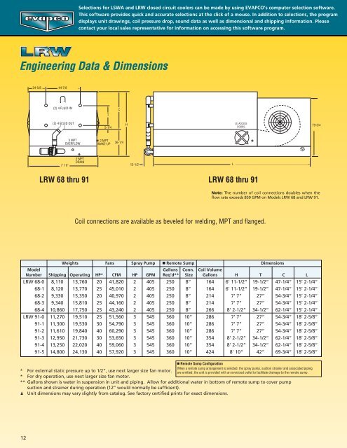
Selections for LSWA and LRW closed circuit coolers can be made by using EVAPCO’s computer selection software.<br />
This software provides quick and accurate selections at the click of a mouse. In addition to selections, the program<br />
displays unit drawings, coil pressure drop, sound data as well as dimensional and shipping information. Please<br />
contact your local sales representative for information on accessing this software program.<br />
Engineering Data & Dimensions<br />
2 MPT<br />
DRAIN<br />
T<br />
5-1/4<br />
2 MPT<br />
MAKE-UP<br />
C<br />
36-1/4<br />
H<br />
13-1/2<br />
■ Remote Sump Configuration<br />
When a remote sump arrangement is selected, the spray pump, suction strainer and associated piping<br />
* For external static pressure up to 1/2”, use next larger size fan motor. are omitted; the unit is provided with an oversized outlet to facilitate drainage to the remote sump.<br />
* For dry operation, use next larger size fan motor.<br />
** Gallons shown is water in suspension in unit and piping. Allow for additional water in bottom of remote sump to cover pump<br />
suction and strainer during operation (12” would normally be sufficient).<br />
Unit dimensions may vary slightly from catalog. See factory certified prints for exact dimensions.<br />
L<br />
(2) ACCESS<br />
DOORS<br />
LRW 68 thru 91 LRW 68 thru 91<br />
Weights Fans Spray Pump ■ Remote Sump Dimensions<br />
Model Gallons Conn. Coil Volume<br />
Number Shipping Operating HP* CFM HP GPM Req’d** Size Gallons H T C L<br />
LRW 68-0 8,110 13,760 20 41,820 2 405 250 8” 164 6’ 11-1/2” 19-1/2” 47-1/4” 15’ 2-1/4”<br />
68-1 8,120 13,770 25 45,010 2 405 250 8” 164 6’ 11-1/2” 19-1/2” 47-1/4” 15’ 2-1/4”<br />
68-2 9,330 15,350 20 40,970 2 405 250 8” 214 7’ 7” 27” 54-3/4” 15’ 2-1/4”<br />
68-3 9,340 15,810 25 44,160 2 405 250 8” 214 7’ 7” 27” 54-3/4” 15’ 2-1/4”<br />
68-4 10,860 17,750 25 43,240 2 405 250 8” 266 8’ 2-1/2” 34-1/2” 62-1/4” 15’ 2-1/4”<br />
LRW 91-0 11,270 19,510 25 51,560 3 545 360 10” 286 7’ 7” 27” 54-3/4” 18’ 2-5/8”<br />
91-1 11,300 19,530 30 54,790 3 545 360 10” 286 7’ 7” 27” 54-3/4” 18’ 2-5/8”<br />
91-2 11,610 19,840 40 60,290 3 545 360 10” 286 7’ 7” 27” 54-3/4” 18’ 2-5/8”<br />
91-3 12,950 21,730 30 53,650 3 545 360 10” 354 8’ 2-1/2” 34-1/2” 62-1/4” 18’ 2-5/8”<br />
91-4 13,250 22,020 40 59,060 3 545 360 10” 354 8’ 2-1/2” 34-1/2” 62-1/4” 18’ 2-5/8”<br />
91-5 14,800 24,130 40 57,920 3 545 360 10” 424 8’ 10” 42” 69-3/4” 18’ 2-5/8”<br />
M<br />
79-3/4<br />
Note: The number of coil connections doubles when the<br />
flow rate exceeds 850 GPM on Models LRW 68 and LRW 91.<br />
Coil connections are available as beveled for welding, MPT and flanged.