Parker Dual Heat Transfer Coils - Eoss.com
Parker Dual Heat Transfer Coils - Eoss.com
Parker Dual Heat Transfer Coils - Eoss.com

Create successful ePaper yourself
Turn your PDF publications into a flip-book with our unique Google optimized e-Paper software.
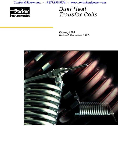
<strong>Parker</strong> <strong>Dual</strong> <strong>Heat</strong><strong>Transfer</strong> <strong>Coils</strong>F e a t u r e s<strong>Parker</strong> <strong>Dual</strong> <strong>Heat</strong> <strong>Transfer</strong> <strong>Coils</strong> are rugged, high eff i c i e n c y,counter-flow heat exchangers for cooling high temperature,high pressure fluid samples such as boiler steam, boilerfeed water, superheat steam, hot chemical solutions andother process fluids.A p p l i c a t i o n sThey allow the operator to withdraw uncontaminatedsamples of a process fluid for laboratory testing at roomtemperature. <strong>Coils</strong> can also be used in continuoussampling systems for on-line process control.Rugged ConstructionThe sturdy tube within a tube design features heavy dutyforged terminal fittings.Tube End ExtensionsPermits the installer the flexibility to utilize any connectionto hook up the inner tube.Simple InstallationConvenient two-hole mounting bracket permits coil to belocated near the point of measurement.No Break In Inner Tu b eTerminal fittings are designed to permit the inner tube to gothrough in one piece, like a thermocouple connection.Forced CounterflowInsures maximum terminal eff i c i e n c y.ASME Code DesignPressure and temperature ratings conform to the applicableASME Boiler Code allowable stress values.3<strong>Parker</strong> Hannifin CorporationInstrumentation Connectors DivisionHuntsville, Alabama
<strong>Parker</strong> <strong>Dual</strong> <strong>Heat</strong><strong>Transfer</strong> <strong>Coils</strong>D i m e n s i o n sInstallation DimensionsI n c h e sSample Tu b e External Tu b e Coolant Tu b e N o . D i m e n s i o n sWa l l A r e a Wa l l M a x . o f We i g h tS i z e O . D . T h i c k . Sq. Ft. O . D . T h i c k . O . D . Wa l l C o i l s L b s . A † C D † E F † G † H †– 4 1 / 4 . 049 . 80 1 / 2 . 049 3 / 8 . 065 15 12 5 13 - 1 / 16 11 - 1 / 4 1 5 5 7 / 8– 6 3 / 8 . 049 1 . 44 3 / 4 . 065 5 / 8 . 083 9 16 8 - 1 / 2 13 9 1 7 7 2– 8 1 / 2 . 065 1 . 93 1 . 083 3 / 4 . 095 10 30 8 16 - 7 / 16 13 - 3 / 4 1 - 1 / 2 6 - 3 / 4 6 - 3 / 4 1 - 7 / 8I n c h e sType of S a m p l e C o o l a n tC o n n e c t i o n S i z e Tube O.D. Tube O.D. K † M † N †– 4 1 / 4 3 / 8 4 . 13 1 . 26 . 57Tube End– 6 3 / 8 5 / 8 3 . 75 1 . 57 . 59E x t e n s i o n– 8 1 / 2 3 / 4 4 . 63 1 . 67 . 69† Average valueTerminal Connection4<strong>Parker</strong> Hannifin CorporationInstrumentation Connectors DivisionHuntsville, Alabama
<strong>Parker</strong> <strong>Dual</strong> <strong>Heat</strong><strong>Transfer</strong> <strong>Coils</strong>Sizing and Design DataHow to orderThe correct part number is easy to arrive at by following the procedure below.Part No. DHTCM AT E R I A LC U = Copper coils – both inner and outerSS = Type 316 Stainless Steel inner coil –Copper outer coilIN = Alloy 600 inner coil – Copper outer coilSIZE OF INNER COIL–4 = 1/4” O.D.–6 = 3/8” O.D.–8 = 1/2” O.D.Typical Sample Capacity of Saturated SteamL b s ./ H r. Steam SampleInner Coil MaterialC o p p e r Stainless Steel & Alloy 600Cooling Wa t e r Max. Outer CoilD H T C 200 Psia 200 Psia 1000 Psia 2500 Psia 3500 Psia F l o w, GPM Pressure PsiS i z e 390 ° F 390 ° F 540 ° F 665 ° F 730 ° F ∆P = 15 p s i (Up TO 200°F)4 80 80 81 89 94 1 . 8 12006 202 188 203 223 236 4 . 5 11008 305 200 270 496 525 10 1000Maximum Pressure / Temperature Rating of Sample Side Tu b eBased on ASME Section VIII Allowable Stress Va l u e sAv a i l a b i l i t yCopper Sample Tube: Available in1/4”, 3/8” and 1/2” with tube endextension.Stainless Steel Sample Tube:Available in 1/4”, 3/8” and 1/2” withtube end extension.Alloy 600 Sample Tube: Availablein 1/4”, 3/8” and 1/2” with tube endextension.5<strong>Parker</strong> Hannifin CorporationInstrumentation Connectors DivisionHuntsville, Alabama
<strong>Parker</strong> <strong>Dual</strong> <strong>Heat</strong><strong>Transfer</strong> <strong>Coils</strong>Typical Installation DiagramStart Up Sequence(All Valves Closed)A . Open cooling water valve #1.B . After adequate cooling water flow is established,gradually open valve #4, then sample intlet valve #2.C . Gradually open sample outlet valve #3 until desiredsample flow rate is obtained (without exceeding suitablesample temperature).D . The position of sample outlet valve #3 should bemaintained for all future sampling.Shut-Off SequenceA . Close sample inlet valve #2.B . Close cooling water intlet valve #1.Sampling SequenceA . Open cooling water inlet valve #1.B . After adequate cooling water flow is established,gradually open sample inlet valve #2 (keeping sampleoutlet valve #3 at its previously determined setting).Note: Always open cooling water first and shut it off last.(It is good practice to occasionally cycle valve #4 so thatwhen needed, it will be operable.)Alloy 600 tubing is re<strong>com</strong>mended for DHTC applications where halides may be present in the media.6<strong>Parker</strong> Hannifin CorporationInstrumentation Connectors DivisionHuntsville, Alabama
<strong>Parker</strong> Hannifin CorporationInstrumentation Connectors DivisionP.O. Box 400004-1504Huntsville, AL 35815-1504USAPhone: (256) 881-2040Fax: (256) 881-5730www.parker.<strong>com</strong>/ICD<strong>Parker</strong> Hannifin plcInstrumentation Products DivisionRiverside RoadPottington Industrial EstateBarnstaple, Devon EX31 1NPEnglandPhone: (44) (1271) 313131Fax: (44) (1271) 373636www.parker.<strong>com</strong>/instrumentationCatalog 4295, 20M, 3/99, GL