Safety & Technical Alert - Eoss.com
Safety & Technical Alert - Eoss.com
Safety & Technical Alert - Eoss.com

You also want an ePaper? Increase the reach of your titles
YUMPU automatically turns print PDFs into web optimized ePapers that Google loves.
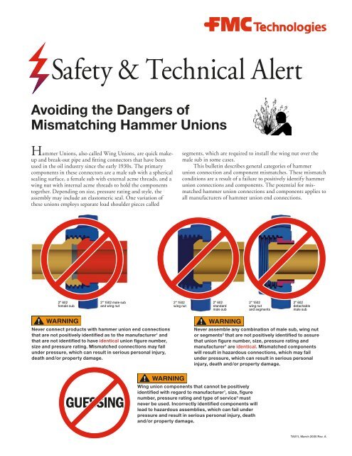
<strong>Safety</strong> & <strong>Technical</strong> <strong>Alert</strong>Avoiding the Dangers ofMismatching Hammer UnionsHammer Unions, also called Wing Unions, are quick makeupand break-out pipe and fitting connectors that have beenused in the oil industry since the early 1930s. The primary<strong>com</strong>ponents in these connectors are a male sub with a sphericalsealing surface, a female sub with external acme threads, and awing nut with internal acme threads to hold the <strong>com</strong>ponentstogether. Depending on size, pressure rating and style, theassembly may include an elastomeric seal. One variation ofthese unions employs separate load shoulder pieces calledsegments, which are required to install the wing nut over themale sub in some cases.This bulletin describes general categories of hammerunion connection and <strong>com</strong>ponent mismatches. These mismatchconditions are a result of a failure to positively identify hammerunion connections and <strong>com</strong>ponents. The potential for mismatchedhammer union connections and <strong>com</strong>ponents applies toall manufacturers of hammer union end connections.2" 602female sub2" 1502 male suband wing nut2" 1502wing nut2" 602standardmale sub2" 1502wing nutand segments2" 602detachablemale subNever connect products with hammer union end connectionsthat are not positively identified as to the manufacturer 1 andthat are not identified to have identical union figure number,size and pressure rating. Mismatched connections may failunder pressure, which can result in serious personal injury,death and/or property damage.Never assemble any <strong>com</strong>bination of male sub, wing nutor segments 2 that are not positively identified to assurethat union figure number, size, pressure rating andmanufacturer 1 are identical. Mismatched <strong>com</strong>ponentswill result in hazardous connections, which may failunder pressure, which can result in serious personalinjury, death and/or property damage.Wing union <strong>com</strong>ponents that cannot be positivelyidentified with regard to manufacturer 1 , size, figurenumber, pressure rating and type of service 3 mustnever be used. Incorrectly identified <strong>com</strong>ponents willlead to hazardous assemblies, which can fail underpressure and result in serious personal injury, deathand/or property damage.TA011, March 2005 Rev. A
Never connect products with hammer union end connections that are not positively identified as to the manufacturer 1 and that arenot identified to have identical union figure number, size and pressure rating. Mismatched connections may fail under pressure,which can result in serious personal injury, death and/or property damage.To avoid connecting a wing nut onto an in<strong>com</strong>patible female sub, users must always assure that these end connections arepositively identified with identical size, figure number and pressure rating.Following are some categories of potential incorrect hammer union connections that may result in hazardousconnections. This list does not include every possible example and is for illustration only. If you haveany doubts or questions about whether you are making up correct hammer union connections, never guessor test. Call FMC Technologies at the phone numbers provided at the end of this document.1. Connecting those products having end connections of the same size, but differentfigure number.An example of this <strong>com</strong>bination is the 2" Figure 602 and the 2" Figure 1502 Union. The threads on the 2" Figure 602female sub, for instance, will slightly engage the internal threads of the 2" Figure 1502 wing nut, resulting in an incorrect andhazardous connection.In the illustration below, the incorrect <strong>com</strong>bination on the left shows the slight engagement of the female sub threads andthe wing nut threads. This type of <strong>com</strong>bination may, under some circumstances, appear to seal and may hold the desiredamount of pressure for a period of time. The <strong>com</strong>bination of 2" Figure 1502 <strong>com</strong>ponents on the right illustrates the correct<strong>com</strong>bination showing full thread engagement.2" 602 female sub 2" 1502 male sub andwing nutAll 2" 1502 <strong>com</strong>ponentsOther examples of the category:• 1-1/2" Figure 600, 602 and 1002 Unions have the same thread.• 5" Figure 400 and 1002 Unions have the same thread.2. Connecting those products having different pressure ratings and having endconnections of the same size and figure number.Examples of this category:• Figure 1502 (and under) Standard Service and Sour Gas 3 Unions have the same thread.• Products with hammer unions attached by pipe threads or welding.If you have any questions call FMC Technologies at the phone numbers provided at the end of thisdocument before making any connections.
Never assemble any <strong>com</strong>bination of male sub, wing nut, or segments 2 that are not positively identified to assure that union figurenumber, size, pressure rating, and manufacturer 1 are identical. Mismatched <strong>com</strong>ponents will result in hazardous connections,which may fail under pressure, which can result in serious personal injury, death, and/or property damage.To avoid assembling in<strong>com</strong>patible wing union <strong>com</strong>ponents together, users must always assure that the wing nuts, malesubs and segments are positively identified as being of the same size, figure number, pressure rating and manufacturer.Following are some categories of potential in<strong>com</strong>patible male sub, wing nut and/or segment assemblies.This list does not include every possible example and is for illustration only.3. Assembly of a wing nut of one size and figure number onto the male sub of anothersize or figure number.An example of this <strong>com</strong>bination is the assembly of a 2" Figure 602 standard male sub (non-detachable) installed in a2" Figure 1502 wing nut.In the illustration on the left below, note the slight amount of engagement of the male sub in the wing nut. Wheninstalled on a female sub, this <strong>com</strong>bination may seal and hold the desired amount of pressure for a period of time. Fullengagement of the correct <strong>com</strong>bination of <strong>com</strong>ponents is shown on the right.2" 1502 wing nut 2" 602 standard male sub All 2" 602 <strong>com</strong>ponents4. Assembly of segments and a nut on an incorrect male sub.An example of these <strong>com</strong>binations is a 2" Figure 602 detachable male sub installed in an assembly with a2" Figure 1502 wing nut and retainer segments.Since many products are machined integrally with male subs, it is important to make sure that the correct union<strong>com</strong>ponents are used. The illustration below on the left shows an incorrect assembly of 2" Figure 602 and 2" Figure 1502<strong>com</strong>ponents. As has been indicated previously, a <strong>com</strong>bination of this type with a female sub may seal and hold a desiredamount of pressure for a period of time. The illustration on the right shows a correct <strong>com</strong>bination of 2" Figure 602<strong>com</strong>ponents.2" 1502 wing nut andsegments2" 602 detachablemale subAll 2" 602 <strong>com</strong>ponents
The misapplication of standard, non-detachable style wing nuts on 2", 3" and 4" Figure 602 and 1002 detachable nut connectionswill result in an unsafe connection leading to separation when under pressure. Failure to avoid this condition may result in death,serious personal injury and severe property damage.Following is another category of potential wing union mismatch that is possible even using wing union<strong>com</strong>ponents of the same size, figure number and manufacturer 1 .5. Assembly of Non-detachable Nuts on Detachable Male SubsAn example of these <strong>com</strong>binations is a 4" Figure 1002 non-detachable nut installed on a 4" Figure 1002 detachable malesub end.Over the years, FMC Technologies has added new wing union designs in response to ever-changing customer andapplication requirements. One of the many innovations introduced by FMC Technologies was the detachable nut designwing union in the 1960s. This design was developed for use on other products such as valves, fittings and swivel joints withintegrally forged end connections. Since that time, FMC Technologies has provided both standard, non-detachable (or“captured”) nut and detachable nut designs for Figure 602, 1002 and 1502 wing unions.Wing unions (illustrated below on left), which are manufactured with non-detachable nuts, require the nut to beassembled to the male sub end before the subs are assembled by welding or thread make-up to other equipment. The detach -able nut wing union design (illustrated below on right) employs a lower profile shoulder on the male sub end and the additionof retainer segments that are inserted between the nut and male sub to retain the nut on the male sub end.Typical nondetachablemale subTypicaldetachablemale subTypical nondetachablenutTypical retainersegmentsTypicaldetachablenutFigure 1502 wing unions employ the same nut on both detachable and non-detachable nut designs. The focus of thisalert is on sizes 2", 3" and 4" Figure 602 and 1002 wing unions, which like the Figure 1502 wing unions are available in bothdetachable and non-detachable nut designs. However, unlike the Figure 1502, these sizes of Figure 602 and 1002 employ onewing nut for non-detachable nut connections and another for detachable nut connections.
The misapplication of standard, non-detachable style wing nuts on 2", 3" and 4" Figure 602 and 1002 detachable nut connectionswill result in an unsafe connection leading to separation when under pressure. Failure to avoid this condition may result in death,serious personal injury and severe property damage.Normally valves, swivel joints and other service line equipment using integral wing union end connections are constructedsuch that it would be impossible to capture a non-detachable nut between the male sub shoulder and the rest of theproduct as shown below.Product withdetachable malesub endProduct withdetachable malesub endDetachable nut haslarger ID than malesub shoulder ODNon-detachable nuthas smaller ID thanmale sub shoulder ODIn some special situations, such as certain wing union adapters and assemblies using threaded or butt weld male subs, it ispossible to slip the non-detachable nut from behind a detachable male sub shoulder (see figure below on left). On the 3" and4" sizes of Figure 602 and 1002 wing unions, the annular engagement between the back of the male sub shoulder and innershoulder of the non-detachable nut engages only slightly - not nearly enough to produce a safe connection (see figure belowon right). This condition would result in a connection that could unexpectedly separate under normal operating conditions.Typical wing union adapterwith 4" 1002 detachable nutmale sub end x female subend of smaller sizeSame adapter with non-detachablenut inappropriately assembled tomale sub end. Notice the very slightannular engagement between nutand male sub shoulder!
The misapplication of standard, non-detachable style wing nuts on 2", 3" and 4" Figure 602 and 1002 detachable nut connectionswill result in an unsafe connection leading to separation when under pressure. Failure to avoid this condition may result in death,serious personal injury and severe property damage.To avoid the unsafe condition described on the previous page, the user must confirm that the appropriate wing nut isbeing used for a given end connection. All 3" and 4" Figure 1002 and 602 detachable nuts currently manufactured by FMCTechnologies have the identifier “DET” forged into the back of detachable nuts (see figure below on left). On these sizes, ifthis identifier is not present, the nut must not be used on detachable wing union connections. Another obvious indication ofinappropriate use of non-detachable nuts on detachable wing union connections of both 3" and 4" Figure 602 and 1002 sizesis the excessive amount of play between the inside diameter of the nut shoulder and the outside diameter of the sub behindthe male sub shoulder (see figure below on the right). If this condition is ever encountered, the wing union connection mustbe disassembled and investigated for mismatch of <strong>com</strong>ponents.3" 602 detachable nut with"DET" identification.4" 1002 non-detachable nutinappropriately assembled to adetached male sub end. Notice theexcessive play between the ID of thenut and male sub OD behind theshoulder.Unlike the 3" and 4" Figure 602 and 1002 wing unions, the 2" size non-detachable nut does not engage the male subshoulder of a detachable nut connection. However, another issue arises if a non-detachable nut is used on a detachable nutconnection. On a properly assembled 2" 602 and 1002 detachable nut wing union connection the nut fully engages thethreads of the female sub (see figure below on left). Using the shorter non-detachable nut, which will appear to properlyassemble over the retainer segments of a detachable male sub end connection, results in inadequate engagement of the femalesub threads by the nut (see figure below on right).This unsafe condition can be encountered on any product employing detachable male sub end connections. To avoid thiscondition, it is important to ensure the correct nut is used. Like the 3" and 4" Figure 602 and 1002, the 2" size also has theidentifier “DET” forged onto the back of the detachable nut. If the identifier is not present, the nut must not be used on adetachable wing union connection.A properly assembled2" 1002 detachable nutwing union connection.2" 1002 non-detachable nutinappropriately used in adetachable union assembly.Notice the resulting lack ofthread engagement with thefemale sub.
The misapplication of standard, non-detachable style wing nuts on 2", 3" and 4" Figure 602 and 1002 detachable nut connectionswill result in an unsafe connection leading to separation when under pressure. Failure to avoid this condition may result in death,serious personal injury and severe property damage.Another way to identify detachable and non-detachable nuts for 2", 3" and 4" sizes of Figure 602 and 1002 wing unionsis by their overall length. The figure below with the ac<strong>com</strong>panying chart shows how the type of nut can be positivelyidentified based on a single measurement.FMC Technologies strongly re<strong>com</strong>mends that, on locations where both non-detachable and detachable nut designs of the2", 3" and 4" Figure 602 and 1002 wing union connections are potentially deployed, all personnel be made aware of thispotential safety issue.LFor Figure Numbers 602 and 1002NominalSize ofNut (in)“L” DimensionNon-detachable NutsFigure602Figure1002DetachableNutsFigure 602and 100221.911.912.5632.062.122.5042.252.383.00Use of non-FMC manufactured parts in FMC Technologies products may result in death, personal injury or property damage. Theuse of non-FMC parts voids all design, type, case, test and quality approvals by third-party certifying authorities and may voidproduct warranty.Never assemble wing union <strong>com</strong>ponents together that are not positively identified as to the manufacturer 1 , service and pressurerating. Failure to do so can result in a connection that may fail under pressure, which can lead to death, serious personal injuryand severe property damage.Do not suspend loads on service lines using wing union connections. Externally applied bending or tensile loads are additive tothe loads already induced by internal pressure. Externally applied loads can result in an over-stress condition leading to catastrophicfailure. If externally applied loads are to be applied, consult factory for limitations.Notes:1. There are many manufacturers of wing union assemblies and <strong>com</strong>ponents that may represent other possible opportunities for<strong>com</strong>ponent mismatch unknown to FMC Technologies. Specific questions regarding identification and use of wing union<strong>com</strong>ponents not manufactured by FMC Technologies must be directed to the appropriate manufacturer.2. Retainer segments for detachable nut wing union connections manufactured by FMC Technologies <strong>com</strong>e in sets of 3. Neverput into service detachable nut wing union connections unless all segments are in place. Markings on FMC Technologieshammer union segments include “FMC”, part number and material reference number. For assistance with positive identificationof segments for appropriate use by size and figure number, contact FMC Technologies or your nearest representative.3. In addition to other identification markings described in this technical alert, <strong>com</strong>ponents intended for sour gas service aremarked “SOUR GAS”, “NACE MR0175” or “SG”. For SOUR GAS SERVICE, use ONLY those <strong>com</strong>ponents that arespecifically identified as being suitable for this service. Refer to the bulletin NACE MR0175/ISO 15156 (latest edition)published by the National Association of Corrosion Engineers.
Warnings and <strong>Safety</strong> InstructionsFMC Technologies cannot anticipate all of the situations a user may encounter while installing and using FMC products. Therefore,the user of FMC products MUST know and follow all applicable industry specifications and practices on the safe installationand use of these products. For additional safety information, refer to FMC Technologies product catalogs, product brochures andinstallation, operating and maintenance manuals, which can be accessed at www.fmctechnologies.<strong>com</strong>/fluidcontrol, or contactFMC Technologies at 800/772-8582.1. Never mix or assemble <strong>com</strong>ponents, parts or end connections with different pressure ratings. Mismatched conditions,including but not limited to that of a 2" Figure 1502 male sub end connected to a 2" Figure 602 female sub, may fail underpressure resulting in death, serious personal injury or severe property damage.2. Never use or substitute non FMC <strong>com</strong>ponents or parts in FMC products or assemblies.3. Never modify or repair FMC products in a manner not specifically directed in instructions published by FMC Technologies.4. Never strike, tighten, loosen or attempt repairs on pressurized <strong>com</strong>ponents or connections.5. Never exceed the rated working pressure of the product.6. Complete and proper make-up of <strong>com</strong>ponents and connections is required to attain rated working pressure. Alwaysapply essential care, attention, handling and inspection to threaded <strong>com</strong>ponents before, during and after make-up.7. Never use severely worn, eroded or corroded products. Contact FMC Technologies for more information on how toidentify the limits of erosion and corrosion.8. Never strike wing union nuts having severely flattened and extruded ears. This condition can result in flying debrisleading to serious personal injury and must immediately be addressed by either grinding off extruded material orremoving the nut from service.9. Always follow safe practices when using products in overhead applications. Products not properly secured could fall.• Never exceed the load rating of lifting devices on products or lifting equipment.• Use of FMC products in suspension applications can result in over-stress conditions leading to catastrophic failure.If externally applied loads are anticipated, consult factory.10. Always follow safe practices when manually lifting and carrying products.11. Always Select only appropriate product and materials for the intended service:• Never expose standard service products to sour gas fluids. (Refer to NACE MR0175). Do not interchange sour gaswith standard service <strong>com</strong>ponents.• Always use appropriate safety precautions when working with ferrous products in below freezing temperatures.Freezing temperatures lower the impact strength of ferrous materials.12. Always follow manufacturer’s instructions and Material <strong>Safety</strong> Data Sheet directions when using solvents.13. Always make certain that personnel and facilities are protected from residual hazardous fluids before disassemblyof any product.14. Whenever leakage is detected from FMC Technologies products, remove them from service immediately to preventdeath, serious personal injury, and/or property damage.SAFETY INSTRUCTIONS: The applications of FMC products are in working environments and systems which must beproperly designed and controlled. <strong>Safety</strong> procedures and policies MUST be clearly established by the user and followed. Always useappropriate protective equipment.For additional copies of this document, download PDF at www.fmctechnologies.<strong>com</strong>/fluidcontrolFMC Technologies, Inc.1803 Gears RoadHouston, TX 77067Phone: 281/260-2121Fax: 281/260-2122FMC Technologies, Inc.2825 West WashingtonStephenville, TX 76401Phone: 254/968-2181Fax: 254/968-5709©Copyright 2005, FMC Technologies, Inc.