Reference Design and Application Note for XAPP1145 - Xilinx
Reference Design and Application Note for XAPP1145 - Xilinx
Reference Design and Application Note for XAPP1145 - Xilinx
- No tags were found...
Create successful ePaper yourself
Turn your PDF publications into a flip-book with our unique Google optimized e-Paper software.
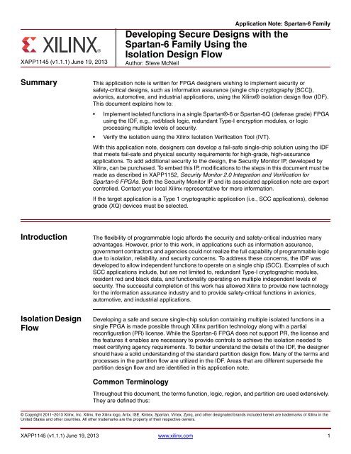
<strong>XAPP1145</strong> (v1.1.1) June 19, 2013<strong>Application</strong> <strong>Note</strong>: Spartan-6 FamilyDeveloping Secure <strong>Design</strong>s with theSpartan-6 Family Using theIsolation <strong>Design</strong> FlowAuthor: Steve McNeilSummaryThis application note is written <strong>for</strong> FPGA designers wishing to implement security orsafety-critical designs, such as in<strong>for</strong>mation assurance (single chip cryptography [SCC]),avionics, automotive, <strong>and</strong> industrial applications, using the <strong>Xilinx</strong>® isolation design flow (IDF).This document explains how to:• Implement isolated functions in a single Spartan®-6 or Spartan-6Q (defense grade) FPGAusing the IDF, e.g., red/black logic, redundant Type-I encryption modules, or logicprocessing multiple levels of security.• Verify the isolation using the <strong>Xilinx</strong> Isolation Verification Tool (IVT).With this application note, designers can develop a fail-safe single-chip solution using the IDFthat meets fail-safe <strong>and</strong> physical security requirements <strong>for</strong> high-grade, high-assuranceapplications. To add additional security to the design, the Security Monitor IP, developed by<strong>Xilinx</strong>, can be purchased. To embed this IP, modifications to the steps in this document must bemade as described in XAPP1152, Security Monitor 2.0 Integration <strong>and</strong> Verification <strong>for</strong>Spartan-6 FPGAs. Both the Security Monitor IP <strong>and</strong> its associated application note are exportcontrolled. Contact your local <strong>Xilinx</strong> representative <strong>for</strong> more in<strong>for</strong>mation.If the target application is a Type 1 cryptographic application (i.e., SCC applications), defensegrade (XQ) devices must be selected.IntroductionIsolation <strong>Design</strong>FlowThe flexibility of programmable logic af<strong>for</strong>ds the security <strong>and</strong> safety-critical industries manyadvantages. However, prior to this work, in applications such as in<strong>for</strong>mation assurance,government contractors <strong>and</strong> agencies could not realize the full capability of programmable logicdue to isolation, reliability, <strong>and</strong> security concerns. To address these concerns, the IDF wasdeveloped to allow independent functions to operate on a single chip (SCC). Examples of suchSCC applications include, but are not limited to, redundant Type-I cryptographic modules,resident red <strong>and</strong> black data, <strong>and</strong> functionality operating on multiple independent levels ofsecurity. The successful completion of this work has allowed <strong>Xilinx</strong> to provide new technology<strong>for</strong> the in<strong>for</strong>mation assurance industry <strong>and</strong> to provide safety-critical functions in avionics,automotive, <strong>and</strong> industrial applications.Developing a safe <strong>and</strong> secure single-chip solution containing multiple isolated functions in asingle FPGA is made possible through <strong>Xilinx</strong> partition technology along with a partialreconfiguration (PR) license. While the Spartan-6 FPGA does not support PR, the license <strong>and</strong>the features it enables are necessary to provide controls to achieve the isolation needed tomeet certifying agency requirements. To better underst<strong>and</strong> the details of the IDF, the designershould have a solid underst<strong>and</strong>ing of the st<strong>and</strong>ard partition design flow. Many of the terms <strong>and</strong>processes in the partition flow are utilized in the IDF. Areas that are different supersede thepartition design flow <strong>and</strong> are identified in this application note.Common TerminologyThroughout this document, the terms function, logic, region, <strong>and</strong> partition are used extensively.They are defined thus:© Copyright 2011–2013 <strong>Xilinx</strong>, Inc. <strong>Xilinx</strong>, the <strong>Xilinx</strong> logo, Artix, ISE, Kintex, Spartan, Virtex, Zynq, <strong>and</strong> other designated br<strong>and</strong>s included herein are trademarks of <strong>Xilinx</strong> in theUnited States <strong>and</strong> other countries. All other trademarks are the property of their respective owners.<strong>XAPP1145</strong> (v1.1.1) June 19, 2013 www.xilinx.com 1
Isolation <strong>Design</strong> FlowFunctionLogicRegion/Area Group/pblockPartitionA collection of logic that per<strong>for</strong>ms a specific operation, e.g., an AES encryptor.Circuits used to implement a specific function, <strong>for</strong> example, a flip-flop (FF),lookup table (LUT), block RAM, etc.A physical area configured to implement logic.A user-defined logical construct that can be used to isolate one piece of hierarchyfrom another.Isolation <strong>Design</strong> FlowA secure or safety-critical solution can be achieved while preserving FPGA design techniques<strong>and</strong> coding styles with only moderate modifications to the development flow. IDF developmentrequires the designer to consider floorplanning much earlier in the design process to ensurethat proper isolation is achieved in logic, routing, <strong>and</strong> I/O blocks (IOB). In addition to earlyfloorplanning, the development flow is partition based (i.e., each function a user desires toisolate must be at its own level of hierarchy). From here, one of two approaches can be taken.To ensure that unwanted optimization of redundancy does not occur, each isolated functionmust be synthesized <strong>and</strong> implemented independently of the other partitions. After eachpartition is implemented, the design is merged into a flattened FPGA design <strong>for</strong> deviceconfiguration. To use other techniques to prevent such optimization, the designer cansynthesize the full design while being careful to maintain at least one level of hierarchy suchthat IDF constraints can be applied to each partition that requires isolation. While this flowrequires the FPGA designer to break away from traditional FPGA development flows, thepartition approach does have certain advantages. If an isolated partition requires a change latein the design cycle, only that specific function is modified while the remaining partitions remainunchanged.<strong>Note</strong>: All logic should belong to an isolated partition except <strong>for</strong> global clocks, resets, <strong>and</strong> IOBs.To achieve an FPGA based IDF solution, a few unique design details must be adhered to. Thedesigner should carefully consider all aspects of these design details, which are explained indetail in subsequent sections of this application note. These considerations include:• Each isolated function must be in its own partition• Each partition must consist of a single module instantiation• A fence must be used to separate isolated partitions within a single chip• IOBs must be inferred or instantiated inside isolated partitions <strong>for</strong> proper isolation of theIOB• On-chip communication between isolated functions is achieved through the use of trustedrouting<strong>XAPP1145</strong> (v1.1.1) June 19, 2013 www.xilinx.com 2
<strong>Reference</strong> <strong>Design</strong><strong>Reference</strong><strong>Design</strong>For clarity, an example design (Figure 1) is used throughout this application note to describethe design details <strong>and</strong> tool flow. In addition, this design has been implemented with the ISE®tools using the partial reconfiguration licensed features, verified by IVT <strong>and</strong> provided to thedesigner as a reference.X-Ref Target - Figure 1resetpush_buttonAESAES_RCOMPAREledclkX1145_01_063011Figure 1:An SCC Solution Using IDF Implementing Two Redundant AES Modules <strong>and</strong>Compare LogicThe example design consists of two redundant advanced-encryption-st<strong>and</strong>ard (AES)encryption modules whose outputs are sent to a comparator block. The redundant AESencryption modules <strong>and</strong> compare functions are all isolated within a single FPGA, as shown inthe FPGA Editor view in Figure 2.<strong>XAPP1145</strong> (v1.1.1) June 19, 2013 www.xilinx.com 3
<strong>Reference</strong> <strong>Design</strong>X-Ref Target - Figure 2TrustedRoutesAESAES_RCOMPAREX1145_02_062811Figure 2: Implemented SCC Solution from Figure 1For simplicity, the AES modules are 128-bit engines running in codebook mode with a staticplain-text word. The design can inject errors via a pushbutton located on one of the AESengines. An LED, driven by the comparison block, indicates when the outputs of the AESmodules do not match. While this architecture is chosen somewhat arbitrarily <strong>and</strong> is not meantto represent an actual user design, it does provide a valuable example in explaining SCCdesign details. Table 1 lists the ports <strong>and</strong> IOBs of each module.Table 1: <strong>Reference</strong> <strong>Design</strong> IOB <strong>for</strong> Each Isolated Module Including the Top LevelModule Module Inputs Module OutputsTOP clk, reset, push_button ledAESAES_RCOMPAREclk, reset, push_button, start, mode,load, key, data_inclk, reset, push_button, start, mode,load, key, data_inclk, reset, done1, done2, data_in1,data_in2data_out, done, reset_outdata_out, donereset_out, start_aes1, start_aes2,load_aes1, load_aes2, ledPer IDF details, the reference design implementation is per<strong>for</strong>med using modular synthesis.Each function to be isolated has its own level of hierarchy <strong>and</strong> is implemented independentlyfrom the others. When completed, the independent modules are then merged together using<strong>XAPP1145</strong> (v1.1.1) June 19, 2013 www.xilinx.com 4
<strong>Reference</strong> <strong>Design</strong>the PlanAhead tool during the import phase of the project generation. Figure 3 shows thehierarchy of the reference design.X-Ref Target - Figure 3SCC_LAB_TOPAESCOMPAREAES_RKEY_EXPANDERKEY_EXPANDERX1145_03_062811Figure 3:Hierarchy <strong>for</strong> the SCC Implementation of the <strong>Reference</strong> <strong>Design</strong>Additional lower level hierarchy is allowed <strong>for</strong> each function. In addition, there is no theoreticallimit on the number of functions allowed. For example, if the Security Monitor is to be integratedinto this design, it is a fourth function with its own hierarchy under Top. As a companion to thisreference design, XAPP1104, Implementation of a Fail-Safe <strong>Design</strong> in the Spartan-6 FamilyUsing ISE <strong>Design</strong> Suite 12.4 details step-by-step instructions on generating a similar referencedesign <strong>and</strong> can be found on the Isolation <strong>Design</strong> Flow page on <strong>Xilinx</strong>.com.Isolation FenceThe complexity <strong>and</strong> density of the Spartan-6 or Spartan-6Q device might seem to preclude anyefficient isolation methodology. In addition, the difficulty of per<strong>for</strong>ming an isolation analysis isassumed to be magnified considering there are 13 members of the Spartan-6 family. However,<strong>Xilinx</strong> FPGAs are modular tile-based devices. No matter which device is chosen, the FPGAconsists of the same basic building blocks tiled over <strong>and</strong> over again. In theSpartan-6 architecture, the basic building blocks are composed of CLBs (LX <strong>and</strong> MX),block RAM, DSPs, etc. Each tile is constructed of some hardened logic <strong>and</strong> one or moreGeneral Routing Matrix (GRM) blocks. Analysis of the FPGA is done at the tile level, <strong>and</strong> this ishow isolation fences are determined (what tiles are valid <strong>and</strong> how many). A high-level view ofthis construction is shown in Figure 4.<strong>XAPP1145</strong> (v1.1.1) June 19, 2013 www.xilinx.com 5
<strong>Reference</strong> <strong>Design</strong>X-Ref Target - Figure 41 CLB (LX) TileGRM GRM SLICE-L SLICE-X GRM SLICE-MSLICE-XGRMGRMDSP48A1GRM SLICE-L SLICE-X GRM SLICE-MGRM GRM SLICE-L SLICE-X GRM SLICE-MSLICE-XSLICE-XGRMGRMRAMB161 BRAMTileGRM GRM SLICE-L SLICE-X GRM SLICE-MSLICE-XGRMGRM GRM SLICE-L SLICE-X GRM SLICE-MSLICE-XGRM1 DSPTileGRMDSP48A1GRM SLICE-L SLICE-X GRM SLICE-MGRM GRM SLICE-L SLICE-X GRM SLICE-MSLICE-XSLICE-XGRMGRMRAMB16GRM GRM SLICE-L SLICE-X GRM SLICE-MSLICE-XGRM1 CLB (MX) TileX1145_04_070811Figure 4:Representation of the Tile-Based Spartan-6 ArchitectureTo achieve isolation within a single device, the concept of a fence is introduced. The fence isjust a set of unused tiles, as described above, in which no routing or logic is present. The resultsof the isolation analysis per<strong>for</strong>med by <strong>Xilinx</strong> shows that one or sometimes two such tiles placedbetween isolated regions guarantee(s) that no single point of failure exists that wouldcompromise the isolation between the two regions. An example of fence placement betweentwo isolated modules is shown in Figure 5.<strong>XAPP1145</strong> (v1.1.1) June 19, 2013 www.xilinx.com 6
<strong>Reference</strong> <strong>Design</strong>X-Ref Target - Figure 5GRM GRM SLICE-L SLICE-X GRM SLICE-MSLICE-XGRMGRMDSP48A1GRM SLICE-L SLICE-X GRM SLICE-MGRM GRM SLICE-L SLICE-X GRM SLICE-MSLICE-XSLICE-XGRMGRMRAMB16GRM GRM SLICE-L SLICE-X GRM SLICE-MSLICE-XGRMGRM GRM SLICE-L SLICE-X GRM SLICE-MGRMDSP48A1GRM SLICE-LISOLATEDMODULESLICE-XGRMSLICE-MGRM GRM SLICE-L SLICE-X GRM SLICE-MSLICE-XSLICE-XSLICE-XGRMGRMGRMRAMB16GRM GRM SLICE-L SLICE-X GRM SLICE-MFENCEGRM GRM SLICE-L SLICE-X GRM SLICE-MSLICE-XSLICE-XGRMGRMGRMDSP48A1GRM SLICE-L SLICE-X GRM SLICE-MGRM GRM SLICE-L SLICE-X GRM SLICE-MSLICE-XSLICE-XGRMGRMFENCERAMB16FENCEGRM GRM SLICE-L SLICE-X GRM SLICE-MSLICE-XGRMGRM GRM SLICE-L SLICE-X GRM SLICE-MSLICE-XGRMGRMDSP48A1GRM SLICE-LSLICE-XGRMISOLATEDMODULESLICE-MGRM GRM SLICE-L SLICE-X GRM SLICE-MSLICE-XSLICE-XGRMGRMRAMB16GRM GRM SLICE-L SLICE-X GRM SLICE-MSLICE-XGRMX1145_05_070811Figure 5:Isolated Functions Separated by a Fence of Unused Logic TilesThe fence location is not directly specified by the designer. It is created indirectly by applyingthe appropriate logic <strong>and</strong> routing constraints to each user-defined region to be isolated. In thereference design, the three functions that must be isolated are the two redundant AESencryption modules <strong>and</strong> the comparator block.Floorplanning the <strong>Reference</strong> <strong>Design</strong>The floorplan of the reference design is shown in Figure 6. Where inter-module communicationis necessary, regions must be coincident with each other with a fence tile between the twointended regions. Refer to On-Chip Communication, page 14 <strong>for</strong> more details.<strong>XAPP1145</strong> (v1.1.1) June 19, 2013 www.xilinx.com 7
<strong>Reference</strong> <strong>Design</strong>X-Ref Target - Figure 6AESTrusted Routing ChannelBetween AES <strong>and</strong> COMPAREFence RegionFence RegionCOMPAREFence RegionAES_RTrusted Routing ChannelBetween AES_R <strong>and</strong> COMPAREX1145_06_063011Figure 6:Floorplan of the <strong>Reference</strong> <strong>Design</strong>To constrain the logic to a specific region of the FPGA, the AREA_GROUP constraint is utilized.This constraint is applied to an instance in the HDL representing the function to be isolated. Inthis example, each of the AES encryption modules <strong>and</strong> comparator functions has anAREA_GROUP constraint applied to it. For more in<strong>for</strong>mation on the AREA_GROUP constraint<strong>and</strong> the FPGA coordinate system, see the Constraints Guide installed during softwareinstallation. The first step in creating the AREA_GROUP constraint is to analyze the region thefunction is to be mapped into to ensure that enough dedicated resources exist. The dedicatedresources can be IOB, FFs, LUTs, block RAM, DSP48E slices, etc. The PlanAhead tool, whichrelates AREA_GROUPs with physical blocks (PBLOCKS), can be used to assist the designerin this analysis.The next step is to assign the HDL instance name of the module to a user-specifiedAREA_GROUP name. In the reference design, the HDL module instance names areU1_AES1, U2_AES2, <strong>and</strong> U3_Comp. The assignment of the instance name to theAREA_GROUP <strong>for</strong> the reference design is:"INST "U1_AES1" AREA_GROUP = "pblock_U1_AES1";"INST "U2_AES2" AREA_GROUP = "pblock_U2_AES2";"INST "U3_Comp" AREA_GROUP = "pblock_U3_Comp";Next, AREA_GROUPs must be assigned to a specific range of logic in the FPGA.AREA_GROUPs can be defined in terms of SLICEs, RAMB16s, IOBs, ILOGICs, OLOGICs,PLLs, DCMs, IODELAYs, BUFGMUXs, GTPs, DSP48s, etc. The generic syntax <strong>for</strong> addingcomponents to an area group is:AREA_GROUP “” RANGE=_XaYb:_XcYd;Where:• = name of area group• = name of desired component• SLICE• RAMB16• DSP48• IOB• ILOGIC<strong>XAPP1145</strong> (v1.1.1) June 19, 2013 www.xilinx.com 8
<strong>Reference</strong> <strong>Design</strong>• OLOGIC• PLL• DCMThe component name can be identified by pointing at it in the PlanAhead tool <strong>and</strong> readingit off the bottom right h<strong>and</strong> of the screen.• a, b, c, d = Coordinates of the starting component <strong>and</strong> the ending componentsCoordinates can also be identified from the same location in the bottom right-h<strong>and</strong> cornerof the PlanAhead tool that the component name was identified. Some examples of thissyntax are as follows:• AREA_GROUP "pblock_U1_AES1" RANGE=SLICE_X72Y190:SLICE_X115Y191;• AREA_GROUP "pblock_U1_AES1" RANGE=DSP48_X3Y38:DSP48_X3Y47;• AREA_GROUP "pblock_U1_AES1" RANGE=RAMB16_X4Y76:RAMB16_X5Y94;• AREA_GROUP "pblock_U1_AES1" RANGE=ILOGIC_X2Y142:ILOGIC_X2Y239;• AREA_GROUP "pblock_U1_AES1" RANGE=OLOGIC_X2Y142:OLOGIC_X2Y239;• AREA_GROUP "pblock_U1_AES1" RANGE=PAD133,PAD158;<strong>Note</strong>: I/O pads are added to the area group range by a unique method. Pads must be added individuallybecause they are not ranged sites.Although the reference design does not use DSPs or block RAMs, they have been added to thearea group so that the routing resources contained by these blocks can be used. As a generalrule, all available resources should be assigned to the area group unless there is a specificneed to exclude that resource. This is the default selection when generating the constraint fileusing the PlanAhead tool. These constraints can be generated by h<strong>and</strong> or with therecommended PlanAhead design analysis tool. As an exception to this rule, the hardenedmemory controller block (MCB) should only be added to an area group if it is used in thatregion.<strong>XAPP1145</strong> (v1.1.1) June 19, 2013 www.xilinx.com 9
<strong>Reference</strong> <strong>Design</strong>Communicating with Isolated FunctionsCommunication between isolated functions in the FPGA <strong>and</strong> other components within a systemoccurs through user IOBs. However, to maintain isolation from logic to the IOBs, <strong>and</strong> ultimatelythe PCB, the IOBs must be considered to be part of the isolation function <strong>and</strong> contained in theisolated region associated with that function. If the IOBs are not included in the isolated region,any routing from the isolated function to the IOBs cannot be contained to stay in the isolatedregion, <strong>and</strong> thus isolation cannot be guaranteed (Figure 7).X-Ref Target - Figure 7Isolation FaultX1145_07_072911Figure 7:An Uncontrolled Route from an IOB to an Isolated Region<strong>XAPP1145</strong> (v1.1.1) June 19, 2013 www.xilinx.com 10
<strong>Reference</strong> <strong>Design</strong>When the IOBs are included in the isolated region, the routing is controlled <strong>and</strong> isolation isguaranteed (Figure 8).X-Ref Target - Figure 8X1145_08_062811Figure 8:Controlled Routing Between an IOB <strong>and</strong> its Isolated RegionCommunication between two isolated functions within the FPGA typically occurs internallyusing trusted routing. A less preferable alternative is to use IOBs to go off-chip <strong>and</strong> then backon again into a different region. Each of these alternatives has specific constraints that must beconsidered be<strong>for</strong>e choosing how to communicate with isolated functions.<strong>Note</strong>: In the Spartan-6 architecture, the area group does not surround the actual IOB pad. Rather, itsurrounds the logic associated with that pad (ILOGIC, OLOGIC). In addition to the area group surroundingthe logic, the PAD_RANGE constraint must be set to add the pad itself to the area group.Off-Chip CommunicationIf an isolated function has inputs or outputs that must come from or go off-chip, these signalsmust have their IOBs inferred inside an isolated partition. While this is different from st<strong>and</strong>ardFPGA design practice, it is required in order to have control over the routing of the signals fromthe IOB to the function. If the IOB is not part of the isolated partition, there is no control overhow the signal is routed from the IOB to the logic. St<strong>and</strong>ard design practice is to define all of theFPGA IOBs in the top-level port map (<strong>for</strong> VHDL users). During synthesis, all of the IOBs areinferred at the highest level of the target hierarchy. However, in the IDF, IOB insertion isspecifically controlled <strong>and</strong> usually happens at the lower level partitions. For simulation, all of theIOBs are still defined at the top level in the IDF. However, where the IOBs are inferred dependson whether or not the signal must be isolated. For the IDF, the only signals that should have IOBbuffers inferred at the top level are global clocks, resets, <strong>and</strong> other control signals that do notrequire isolation. All other signals that go off-chip should have their IOBs inferred at the lowerlevel modules. Because the IDF is modular <strong>and</strong> each isolated function is implementedindependently of the other, the development tools treat each module port declaration as beingthe design top level. Because an isolated function might not be at the top level, a method mustbe employed to identify which signals the development tools should add IOBs to <strong>and</strong> which it<strong>XAPP1145</strong> (v1.1.1) June 19, 2013 www.xilinx.com 11
<strong>Reference</strong> <strong>Design</strong>should not. A simple <strong>Xilinx</strong> Synthesis Tool (XST) attribute statement is used to keep IOBs frombeing inferred:attribute buffer_type: string;attribute buffer_type of signal_name: signal is "none";<strong>Note</strong>: All IOBs are still identified in the top level of the hierarchy to enable design verification throughst<strong>and</strong>ard functional <strong>and</strong> back-annotated timing simulations. For the reference design, each of thesefunctions must be isolated from one another, <strong>and</strong> each of these functions contain dedicated IOBs. To inferonly the global clock <strong>and</strong> reset in the top-level port declaration, the attribute is applied to all signals thatshould not have their IOB inserted.Example syntax <strong>for</strong> the top-level HDL, SCC_LAB_TOP.vhd, is:entity SCC_LAB_TOP isPort (push_buttonresetclkled);: in std_logic;: in std_logic;: in std_logic;: out std_logicattribute buffer_type: string;attribute buffer_type of push_buttonattribute buffer_type of reset--attribute buffer_type of clkattribute buffer_type of led: signal is "none"; -- Pin in AES1: signal is "none"; -- Pin inside AES1: signal is "none"; -- Top Level Pin: signal is "none"; -- Pin in Compareend SCC_LAB_TOP;<strong>Note</strong>: The line commented out means that no such attribute is applied. This is to show that clk pin is partof this level of hierarchy <strong>and</strong> needs to get its IOB inferred here.To infer only the AES1 dedicated off-chip IOBs in the aes module, the attribute is applied to allsignals that are not meant to be external IOBs. Example syntax <strong>for</strong> the aes HDL, aes.vhd, is:entity aes isport(clk: in std_logic;reset: in std_logic;push_button : in std_logic; -- must be put in AES1 block <strong>for</strong> inc flowstart : in std_logic; -- to initiate the encryption/decryption-- process after loadingmode : in std_logic; -- to select encryption or decryptionload : in std_logic; -- to load the input <strong>and</strong> keyskey : in std_logic_vector(63 downto 0);data_in : in std_logic_vector(63 downto 0);reset_out: out std_logic;data_out : out std_logic_vector(127 downto 0);done: out std_logic);attribute buffer_type: string;attribute buffer_type of clk--attribute buffer_type of reset--attribute buffer_type of push_buttonattribute buffer_type of startattribute buffer_type of modeattribute buffer_type of loadattribute buffer_type of keyattribute buffer_type of data_inattribute buffer_type of reset_outattribute buffer_type of data_outattribute buffer_type of done: signal is "none"; -- Top level PIN: signal is "none"; -- Hooked up to IBUF: signal is "none"; -- Hooked up to IBUF: signal is "none"; -- Port: signal is "none"; -- Port: signal is "none"; -- Port: signal is "none"; -- Port: signal is "none"; -- Port: signal is "none"; -- Port: signal is "none"; -- Port: signal is "none"; -- Portend aes;<strong>Note</strong>: The only AES IOBs that go off-chip are the signals push_button <strong>and</strong> reset. All of the other signalsdo not have IOB buffers inferred because they are either inferred elsewhere (<strong>for</strong> example, in the top-levelof hierarchy) or are not required because the signals are internal only.<strong>XAPP1145</strong> (v1.1.1) June 19, 2013 www.xilinx.com 12
<strong>Reference</strong> <strong>Design</strong>To infer only the AES2 dedicated off-chip IOBs in the aes_r module, the attribute is applied toall signals that are not meant to be external IOBs. Example syntax <strong>for</strong> the aes_r HDL,aes_r.vhd, is:entity aes_r isport(clkresetpush_buttonstart: in std_logic;: in std_logic;: in std_logic; -- must be put in aes128_fast block <strong>for</strong> inc flow: in std_logic; -- to initiate the encryption/decryption process-- process after loading: in std_logic; -- to select encryption or decryption: in std_logic; -- to load the input <strong>and</strong> keysmodeloadkey : in std_logic_vector(63 downto 0);data_in : in std_logic_vector(63 downto 0);data_out : out std_logic_vector(127 downto 0);done: out std_logic);attribute buffer_type: string;attribute buffer_type of clkattribute buffer_type of resetattribute buffer_type of push_buttonattribute buffer_type of startattribute buffer_type of modeattribute buffer_type of loadattribute buffer_type of keyattribute buffer_type of data_inattribute buffer_type of data_outattribute buffer_type of done: signal is "none"; -- PIN at top level: signal is "none"; -- PORT only: signal is "none"; -- PORT only: signal is "none"; -- PORT only: signal is "none"; -- PORT only: signal is "none"; -- PORT only: signal is "none"; -- PORT only: signal is "none"; -- PORT only: signal is "none"; -- PORT only: signal is "none"; -- PORT onlyend aes_r;<strong>Note</strong>: The redundant AES function has no external IOBs. There<strong>for</strong>e, the attribute is applied to all of thesignals.To infer only the COMPARE dedicated off-chip IOBs in the compare module, the attribute isapplied to all signals that are not meant to be external IOBs. Example syntax <strong>for</strong> the compareHDL, compare.vhd, is:entity compare isport(clk: in std_logic;reset : in std_logic;reset_out : out std_logic;done1 : in std_logic;done2 : in std_logic;start_aes1 : out std_logic;start_aes2 : out std_logic;load_aes1 : out std_logic;load_aes2 : out std_logic;data_in1 : in std_logic_vector(127 downto 0);data_in2 : in std_logic_vector(127 downto 0);led: out std_logic);attribute buffer_type: string;--attribute buffer_type of led: signal is "none"; -- PIN at top levelattribute buffer_type of clk: signal is "none"; -- PORT onlyattribute buffer_type of reset: signal is "none"; -- PORT onlyattribute buffer_type of reset_out : signal is "none"; -- PORT onlyattribute buffer_type of done1: signal is "none"; -- PORT onlyattribute buffer_type of done2: signal is "none"; -- PORT onlyattribute buffer_type of start_aes1 : signal is "none"; -- PORT onlyattribute buffer_type of start_aes2 : signal is "none"; -- PORT onlyattribute buffer_type of load_aes1 : signal is "none"; -- PORT onlyattribute buffer_type of load_aes2 : signal is "none"; -- PORT onlyattribute buffer_type of data_in1 : signal is "none"; -- PORT onlyattribute buffer_type of data_in2 : signal is "none"; -- PORT onlyend compare;<strong>Note</strong>: The only COMPARE IOB that goes off-chip is the signal led. All other signals do not have IOBbuffers inferred because they are either inferred elsewhere (<strong>for</strong> example, in the top-level hierarchy) or arenot required because the signals are internal only.<strong>XAPP1145</strong> (v1.1.1) June 19, 2013 www.xilinx.com 13
<strong>Reference</strong> <strong>Design</strong>In summary, isolation from the logic, through the IOB <strong>and</strong> onto the PCB, can be achieved byusing the buffer_type attribute statement. This attribute dictates which signals have IOB buffersinferred to guarantee isolation without altering the coding style.On-Chip CommunicationWhen communication between isolated functions is required, there are two possible solutions:• Trusted routing (preferred method). For details on the user rules required when usingTrusted routing, refer to Trusted Routing Rules, page 25.• Signals can be taken off-chip from one isolated region, routed through the PCB, <strong>and</strong> thenbrought back on-chip in a separate isolated region. While possible, this method is notpreferred due to both complexity <strong>and</strong> practicality.Constraining PlacementPlacement constraint is now achieved by the addition of components to the area group.Examples of this syntax with respect to the AES1 isolated function are listed below. A full listingof this syntax can be found in UG625, <strong>Xilinx</strong> Constraints Guide.• AREA_GROUP "pblock_U1_AES1" RANGE=DSP48_X3Y38:DSP48_X3Y47;• AREA_GROUP "pblock_U1_AES1" RANGE=PAD133,PAD158;• AREA_GROUP "pblock_U1_AES1" RANGE=RAMB8_X4Y76:RAMB8_X5Y95;• AREA_GROUP "pblock_U1_AES1" RANGE=SLICE_X72Y190:SLICE_X115Y191;Components <strong>and</strong> resources not in an area group cannot be used. Because this includestop-level clock components such as DCMs, an additional constraint is necessary. Theconstraint PRIVATE = NONE is a directive to the top-level function that allows top-level routesto use components owned by each area group. In the included reference design, the PRIVATEconstraint is set to NONE <strong>for</strong> each isolated function.• AREA_GROUP "pblock_U1_AES1" PRIVATE = NONE;• AREA_GROUP "pblock_U2_AES2" PRIVATE = NONE;• AREA_GROUP "pblock_U3_Comp" PRIVATE = NONE;<strong>Note</strong>: NONE is the default setting <strong>for</strong> the PRIVATE constraint. Even if not specifically set, this is thepresumed value.Constraining RoutingRouting control is no longer controlled using constraints. Rather, routing is controlled usingphysical ownership. No resource can be controlled if it is not physically owned (included in anarea group statement). Global logic (DCM, PLL, BUFG, etc.) can use any resource as long asit is physically owned. Local logic (logic <strong>and</strong> routing of an isolated function) can only useresources physically owned by its own isolated region.Constraint SummarySome initial architecting <strong>and</strong> floorplanning of the FPGA, coupled with a small list of constraints,are all that is required to achieve isolation of specific functions within a single Spartan-6 orSpartan-6Q FPGA. The definition of whether a function is reconfigurable or simply isolated isno longer contained in the user constraint file (UCF). It is determined in the PlanAhead tool bysetting the module as a partition <strong>and</strong> then attaching the SCC_ISOLATED attribute to it.All constraints applied to the compare function are shown below.INST "U3_Comp" AREA_GROUP = "pblock_U3_Comp";AREA_GROUP "pblock_U3_Comp" RANGE=SLICE_X104Y105:SLICE_X127Y150;AREA_GROUP "pblock_U3_Comp" RANGE=DSP48_X3Y28:DSP48_X3Y35;AREA_GROUP "pblock_U3_Comp" RANGE=ILOGIC_X35Y102:ILOGIC_X35Y133;<strong>XAPP1145</strong> (v1.1.1) June 19, 2013 www.xilinx.com 14
Isolation Verification ToolAREA_GROUP "pblock_U3_Comp" RANGE=IODELAY_X35Y102:IODELAY_X35Y133;AREA_GROUP "pblock_U3_Comp" RANGE=OLOGIC_X35Y102:OLOGIC_X35Y133;AREA_GROUP "pblock_U3_Comp" RANGE=RAMB16_X4Y54:RAMB16_X5Y72;AREA_GROUP "pblock_U3_Comp" RANGE=RAMB8_X4Y54:RAMB8_X5Y73;AREA_GROUP "pblock_U3_Comp" PRIVATE=NONE;AREA_GROUP "pblock_U3_Comp" RANGE=PAD190;IsolationVerification ToolIVT verifies that an FPGA design partitioned into isolated regions meets stringent st<strong>and</strong>ards <strong>for</strong>fail-safe design. IVT is used at two stages in the FPGA design process. Early in the design flow,IVT is used to per<strong>for</strong>m a series of design rule checks on floorplans <strong>and</strong> pin assignments. Useof IVT at this stage in the design flow is optional but highly recommended. The goal of the UCFchecking is to identify potential isolation problems be<strong>for</strong>e commitment to board layout. After thedesign is complete, IVT is used again to validate that the required isolation is built into thedesign. The use of IVT at this stage in the design flow is m<strong>and</strong>atory, <strong>and</strong> the results must besupplied to a certifying agency <strong>for</strong> verification. IVT is a comm<strong>and</strong> line tool, running underWindows 2000, Windows XP, Windows 7, <strong>and</strong> Linux operating systems <strong>and</strong> with the releasedpartial reconfiguration software installed. The directory containing the <strong>Xilinx</strong> executables <strong>and</strong>dynamic link libraries must be listed in the PATH environment variable <strong>for</strong> IVT to locate them.Constraint Checking (IVT - UCF Mode)IVT, in UCF mode, checks the following:• Pins from different isolation groups are not physically adjacent, vertically or horizontally, atthe die.• Pins from different isolation groups are not physically adjacent at the package. Adjacencyis defined in eight compass directions: north, south, east, west, northeast, southeast,northwest, <strong>and</strong> southwest.• Pins from different isolation groups are not co-located in an IOB bank.• While IVT does fault such conditions, only specific security related applications requiresuch bank isolation. The majority of applications allow <strong>for</strong> sharing of banks. Banksharing is dependent on the specific application.• The AREA_RANGE constraints in the UCF are defined such that a minimum of a onetile-wide fence exists between isolated regions.Because the UCF file might not specify the target device or package, they must be specified viathe comm<strong>and</strong> line. The association between IVT isolation groups <strong>and</strong> user-defined area groupsis also specified on the comm<strong>and</strong> line. The ability <strong>for</strong> the user to associate an IVT isolationgroup to the user-defined area groups allows <strong>for</strong> more than one area group to belong to a singleIVT isolation group. An example of IVT execution is:ivt -f parameter_file_name.txtAvailable comm<strong>and</strong>-line arguments <strong>for</strong> IVT operation on the UCF are shown in Table 2.Table 2: IVT Comm<strong>and</strong>-Line Arguments <strong>for</strong> UCF ModeIVT Comm<strong>and</strong> Line Argument-device device_name-package package_name-group isolation_grouparea_group[-pig pin_isolation_groups[.pig]][-output output[.rpt]]DescriptionSpecifies the device.Specifies the package.Associates the area group name to anarbitrary isolation group name. At leasttwo distinct isolation groups are required.If omitted, no pin-related analysis isper<strong>for</strong>med.Name of the output file.<strong>XAPP1145</strong> (v1.1.1) June 19, 2013 www.xilinx.com 15
Isolation Verification ToolTable 2: IVT Comm<strong>and</strong>-Line Arguments <strong>for</strong> UCF Mode (Cont’d)IVT Comm<strong>and</strong> Line Argument[-verbose][-f argument_file]constraint_file[.ucf]DescriptionWrites out all IVT reporting in<strong>for</strong>mation.Comm<strong>and</strong>-line arguments are stored inan external file.Constraint file <strong>for</strong> the design (UCF).<strong>Note</strong>s:1. Optional arguments are in brackets "[ ]". Italics denote variables.IVT UCF Input FilesIVT, in UCF mode, requires two input files but accepts three, with the third one being aparameter file to reduce the length of the comm<strong>and</strong> line. From these inputs, IVT outputs twounique reports. The text report is the official output <strong>for</strong> use in an evaluation while the second, agraphical output, is useful <strong>for</strong> quick location of any isolation faults. Figure 9 represents a blockdiagram of the inputs <strong>and</strong> outputs of IVT while in UCF mode.X-Ref Target - Figure 9.PIGIVTReport.UCFIVTIVTDiagram.IVTX1145_09_063011Figure 9:IVT Inputs <strong>and</strong> Outputs in UCF ModeUser Constraint FileThe UCF is the floorplan of the user design.Parameter FileThe comm<strong>and</strong>-line arguments <strong>for</strong> the parameter file (IVT) are somewhat long, especially <strong>for</strong>checking UCFs. There<strong>for</strong>e, it is recommended that a file containing the arguments be created<strong>and</strong> supplied to IVT, rather than typing them directly at the comm<strong>and</strong> line. Arguments can bespread across multiple lines, with blank lines <strong>and</strong> lines beginning with # ignored (comments).The UCF mode parameter file <strong>for</strong> the reference design is shown here.-device xc6slx150t -package fgg676# Groups Isolation Group Area Group#---------- --------------- -------------------------group AES pblock_U1_AES1-group AES_r pblock_U2_AES2-group COMPARE pblock_U3_Comp<strong>XAPP1145</strong> (v1.1.1) June 19, 2013 www.xilinx.com 16
Isolation Verification Tool# Pin Isolation Groups-pig SCC_LAB.pig# User Constraint File../PlanAhead/FloorPlan_SCC/FloorPlan_SCC.runs/config_1/SCC_LAB_TOP.ucf# Output Report File-output SCC_LAB_ucf.rptPin Isolation Group File<strong>Design</strong>s containing red <strong>and</strong> black logic <strong>and</strong> routing can require isolation at the device inputs<strong>and</strong> outputs. In this scenario, a pin isolation group (PIG) file is required. The PIG file specifiespins belonging to each isolation group, allowing IVT to per<strong>for</strong>m design rule checks. The PIG file<strong>for</strong>mat is simple <strong>and</strong> allows an FPGA designer to cut <strong>and</strong> paste the I/O location constraintsdirectly from the UCF into the PIG text file (file extension .pig). An isolation group is definedwith this syntax:ISOLATION_GROUP group_name BEGIN.. #Cut <strong>and</strong> paste IOB location. #constaints from UCF here.END ISOLATION_GROUP<strong>Note</strong>: Only the net names are significant. All other syntax within the IOB location constraints is ignored.Below is an example PIG file from the reference design.# Place all Global (top level) signals here (each commented out)# NET "clk" LOC = U25;ISOLATION_GROUP AES BEGINNET "push_button" LOC = N25;NET "reset" LOC = M21;END ISOLATION_GROUPISOLATION_GROUP AES_r BEGIN# There are no pins in AES_rEND ISOLATION_GROUPISOLATION_GROUP COMPARE BEGINNET "led" LOC = V24;END ISOLATION_GROUP<strong>Note</strong>: The net syntax is a copy/paste from the actual UCF file. The clock net is commented out becauseit is a top-level net that is not associated with any specific isolated region. The other IOB declarations areembedded in their appropriate ISOLATION_GROUP.Final Isolation Verification (IVT - NCD Mode)IVT, in NCD mode, checks the following:• Pins from different isolation groups are not physically adjacent at the die. Adjacency isdefined vertically, in either a north or south direction. Because the I/Os inSpartan-6 FPGAs are in a ring <strong>for</strong>mat, adjacency in the diagonal direction at the cornersof the die is also checked.• Pins from different isolation groups are not physically adjacent in the package. Adjacencyis defined in eight compass directions: north, south, east, west, northeast, southeast,northwest, <strong>and</strong> southwest.• Pins from different isolation groups do not share an I/O bank.• Functions are isolated by a fence consisting of empty user tiles, as defined in Table 4,page 28.<strong>XAPP1145</strong> (v1.1.1) June 19, 2013 www.xilinx.com 17
Isolation Verification ToolIf in<strong>for</strong>mation potentially leaks from one isolated region to another by the introduction of fewerthan the user-supplied number of faults, IVT reports a faulty path. In this context, the faulty pathrefers not to an actual defect present in a design, but rather to a possible defect introduced witha limited number of changes or failures that might occur by accident or by tampering. Anexample of IVT execution is:ivt -f parameter_file_name.txtAvailable comm<strong>and</strong>-line arguments <strong>for</strong> IVT operation on the user design file (NCD) are shownin Table 3.Table 3: IVT Comm<strong>and</strong>-Line Arguments <strong>for</strong> NCD ModeIVT Comm<strong>and</strong> Line Argument-group isolation_groupuser_instance_name-out output[.rpt]DescriptionAssociates an arbitrary group name to an isolated instance inthe user routed design. At least two distinct isolation groupsare required.Name of the output file.-f parameter_file Comm<strong>and</strong>-line arguments stored in an external file.user_design[.ncd]Fully routed user design file (NCD).<strong>Note</strong>s:1. Optional arguments are in brackets "[ ]". Italics denote variables.IVT NCD Input FilesIVT, in NCD mode, requires one input file but accepts two, with the second one being aparameter file to reduce the length of the comm<strong>and</strong> line. From these inputs, IVT outputs twounique reports. The text report is the official output <strong>for</strong> use in an evaluation while the second, agraphical output, is useful <strong>for</strong> quick location of any isolation faults. Figure 10 represents a blockdiagram of the inputs <strong>and</strong> outputs of IVT while in NCD mode.X-Ref Target - Figure 10.NCDIVTReportIVTIVTDiagram.IVTX1145_15_062911Figure 10:IVT Inputs <strong>and</strong> Outputs in NCD ModeUser NetlistThe user netlist, or NCD file, contains the fully routed user design.<strong>XAPP1145</strong> (v1.1.1) June 19, 2013 www.xilinx.com 18
Isolation Verification ToolParameter FileThe comm<strong>and</strong>-line arguments <strong>for</strong> IVT are somewhat long, especially <strong>for</strong> checking UCFs.There<strong>for</strong>e, it is recommended that a file containing the arguments be created <strong>and</strong> supplied toIVT rather than typing them directly at the comm<strong>and</strong> line. Arguments can be spread acrossmultiple lines, with blank lines <strong>and</strong> lines beginning with # ignored (comments). The NCD modeparameter file <strong>for</strong> the reference design is shown here.# comment the next line <strong>for</strong> reduced detail in the report file.-verbose# Groups Isolation Group Instance Name in Final NCD#-------- ---------------- ---------------------------group AES U1_AES1-group AES_r U2_AES2-group COMPARE U3_Comp# Fully Routed designSCC_LAB_TOP.routed.ncd# Output Report File-output SCC_LAB_TOP_ncd.rptIVT OutputAs seen in Figure 9 <strong>and</strong> Figure 10, IVT has two outputs. The first, a graphical file, is useful asa high-level overview of the user design <strong>and</strong> is helpful in quick identification of isolation faults.The second, a text file, is a detailed report that is to be used in any official evaluation. Faults <strong>and</strong>other items of concern are described in this report. The content of these reports is dependenton the mode in which IVT was called (UCF or NCD).UCF ModeIVT, in UCF mode, verifies the user floorplan. Specifically, IVT ensures that user area groupshave the required fence width between them <strong>and</strong> that the IOBs are properly isolated at both thedie <strong>and</strong> package level.Text ReportA typical UCF mode report contains these sections:• Provenance: Includes the date, IVT version, ISE version used <strong>for</strong> the run, ISE versionagainst which IVT was compiled, the location of the ISE installation, the comm<strong>and</strong> line, thecurrent working directory, the output report location, <strong>and</strong> the part/package.• Area range constraints: For each isolation group, lists the corresponding area groups <strong>and</strong>associated site ranges used to define the floorplan of the design.• Package pins, I/O buffers, <strong>and</strong> I/O banks: The pin assignments of the design arepresented with coordinates, I/O banks, isolation groups, <strong>and</strong> net names.• Pin isolation summary: Lists the number of isolation violations <strong>for</strong> die pins (I/O buffers),package pins, <strong>and</strong> I/O banks.• Area fault summary: Lists the number of area ranges from distinct isolation groups that arenot separated by an adequate fence.• Isolation verification summary: Lists the total number of constraints violated, reportscompletion, <strong>and</strong> reports the elapsed time to per<strong>for</strong>m the analysis <strong>and</strong> generate the report.A more detailed description <strong>and</strong> examples can be found in the IVT user guide provided with thereference design.<strong>XAPP1145</strong> (v1.1.1) June 19, 2013 www.xilinx.com 19
Isolation Verification ToolGraphical ReportFor ease of use, IVT outputs a silicon vector graphics (SVG) file. This generic output allows <strong>for</strong>quickly identifying where faults are. While the text report is all-encompassing, the SVG file givesa high-level view of any faults <strong>and</strong> is useful in debugging the user floorplan. Figure 11 shows atypical example of the SVG output as run on the reference design.X-Ref Target - Figure 11IVT SVG Output PlanAhead Tool Floorplan X1145_11_063011Figure 11:SVG Output File (Left) Run on <strong>Reference</strong> <strong>Design</strong> Floorplan Next toActual floorplan (Right)NCD ModeIVT, in NCD mode, makes all the same checks it did in UCF mode but now works on the finalrouted design. Instead of looking at area group isolation, IVT now looks to make sure all thecomponents <strong>and</strong> nets of each isolated module have a valid fence between them.Text ReportA typical NCD mode report contains these sections:• Provenance: Includes the date, IVT version, ISE version used <strong>for</strong> the run, ISE versionagainst which IVT was compiled, location of the ISE installation, comm<strong>and</strong> line, current<strong>XAPP1145</strong> (v1.1.1) June 19, 2013 www.xilinx.com 20
Isolation Verification Toolworking directory, output report location, part/package, <strong>and</strong> the name of the combineddesign.• Isolated Modules: Lists the isolation groups <strong>and</strong> associated design blocks or partial NCDfiles.• Uncategorized User Global Nets: Lists nets (signals) in the design that are above theisolated modules in the design hierarchy <strong>and</strong> might connect isolated functions. All suchnets must be examined <strong>for</strong> their impact on the data separation <strong>and</strong> independencerequirements of the system. Ideally, the only nets listed in this section would be netsspecifically intended to connect isolated functions. In practice, some global clock signalsappear here as well. In the report, uncategorized global nets are said to be “found inmultiple isolation groups.” This is an artifact of the original implementation of IVT in whichmultiple partial NCD files were used to specify isolation groups. Global resources areduplicated in all the partial NCD files.• Categorized Nets: Has many possible subsections corresponding to various categories ofnets that <strong>for</strong> one reason or another are benign with respect to isolation. Examples includeconstants, global clocks, trusted bus macros, <strong>and</strong> clocking inserted automatically tomitigate negative-bias temperature instabilities.• Trusted Bus Macros: Lists all the instances of trusted bus macros in the design <strong>and</strong> thenets connected to them.• Area Range Constraints: For each isolation group, lists the corresponding area groups<strong>and</strong> associated site ranges used to define the floorplan of the design.• Net Fault-Cost Violations (Failing Paths): For Virtex®-4 FPGA designs, lists pairs ofputatively isolated nets that cannot be shown to be sufficiently isolated withfault-cost-based routing search. Examples of low-cost paths between isolated nets arelisted, <strong>and</strong> several customer designs have produced isolation violations. However, in allcases, the violations turned out to be due to insufficient in<strong>for</strong>mation in the cost function,not an actual vulnerability.• Tiles with Net Content Violations: Lists the contents of all tiles that contain isolated logic orrouting from more than one isolation group.• Tiles in the Fence Containing Nets: Lists the contents of tiles that are outside all theisolated area ranges. This list is advisory. It is permissible <strong>for</strong> inter-region signals <strong>and</strong>clocking to exist in the fence. Akin to the list of Uncategorized Global Nets, nets in tiles thatare outside of all isolation groups must be vetted <strong>for</strong> their impact on data separation <strong>and</strong>independence requirements. This section provides low-level details of the specific nodes<strong>and</strong> wire segments used to implement routing in the fence.• Tiles in the Fence Containing Programming: Lists tiles in the fence that are associatedwith components <strong>and</strong> there<strong>for</strong>e are not entirely unused. All such tiles must be examined<strong>for</strong> their impact on the data separation <strong>and</strong> independence requirements of the system.• Tiles in the Fence Containing Used PIPs: Lists tiles containing programmable interconnectpoints (PIPs), which are nodes that have the potential to connect to other nodes. Forexample, suppose a certain type of node spans five horizontal tiles called A, B, C, D, <strong>and</strong>E, <strong>and</strong> that this node has PIPs in tiles A, C, <strong>and</strong> E. This node can be used to connect twoisolated regions provided the only tiles in the fence are B or D.• Tiles with Net Adjacency Violations: Lists all pairs of tiles that are adjacent <strong>and</strong> containisolated logic or routing resources from distinct isolation groups, in other words, pairs oftiles that should be separated by a fence tile.• Package Pins, I/O Buffers, <strong>and</strong> I/O Banks: The pin assignments of the design arepresented with coordinates, I/O banks, isolation groups, <strong>and</strong> the net names.• I/O Buffer Isolation Violations: Lists pairs of I/O buffers from distinct isolation groups thatare adjacent on the die.• I/O Bank Violations: Lists examples of pins from distinct isolation groups that are membersof a single I/O bank.<strong>XAPP1145</strong> (v1.1.1) June 19, 2013 www.xilinx.com 21
Isolation Verification Tool• Package Pin Isolation Violations: Lists pairs of pins from distinct isolation groups that areadjacent on the package.• Isolation Verification Summary: Lists the total number of constraints violated by category,reports completion, <strong>and</strong> reports the elapsed time to per<strong>for</strong>m the analysis <strong>and</strong> generate thereport. For each section of the report containing violations, there is a line in the summarywith a tally of the violations in that section.A more detailed description <strong>and</strong> examples can be found in the IVT user guide.Graphical ReportFor ease of use, IVT outputs an SVG file. This generic output allows <strong>for</strong> quickly identifyingwhere faults are. While the text report is all encompassing, the SVG file gives a high-level viewof any faults <strong>and</strong> is useful in debugging the user floorplan. Figure 12 shows a typical exampleof the SVG output as run on the reference design.X-Ref Target - Figure 12IVT SVG Output Implemented <strong>Design</strong> X1145_12_063011Figure 12:IVT SVG (Left) Run on <strong>Reference</strong> <strong>Design</strong>/FPGA Editor View ofSame <strong>Design</strong> (Right)<strong>XAPP1145</strong> (v1.1.1) June 19, 2013 www.xilinx.com 22
<strong>Design</strong> Guidance<strong>Design</strong>GuidanceSCC <strong>and</strong> the Isolation <strong>Design</strong> FlowSCC is built upon the IDF software flow. IDF, along with significant analysis per<strong>for</strong>med by <strong>Xilinx</strong>,is what allows <strong>for</strong> SCC implementations. SCC is simply a single application using the IDF. IDF,however, is more generic in nature <strong>and</strong> is not that dissimilar from a traditional design flow.Figure 13 shows a flow diagram of both flows side by side.X-Ref Target - Figure 13FPGA Development FlowIsolation <strong>Design</strong> Flow AdditionsFloorplanningConstraintsIsolationGroupsHardwareDescriptionLanguageSynthesisIVTUCF ModeISE SoftwareSettingsTranslationMappingUCF IsolationAnalysisReportUCF FloorplanDiagramPlacement <strong>and</strong>RoutingIsolationGroupsNCDIVTNCD ModeConfigurationBitstreamGenerationNCD IsolationAnalysisReportNCD User TileDiagramX1145_13_070111Figure 13:Partition OverviewThe Isolation <strong>Design</strong> Flow Relative to a Typical FPGA <strong>Design</strong> FlowAll the partition definitions <strong>and</strong> controls are done in the xpartition.pxml file. This file can becreated by h<strong>and</strong> or automatically with the PlanAhead software GUI, <strong>and</strong> is described in the<strong>Design</strong> Preservation Flows chapter in UG748, Hierarchical <strong>Design</strong> Methodology Guide.Creating the xpartition.pxml file automatically is the easier method. The file can be<strong>XAPP1145</strong> (v1.1.1) June 19, 2013 www.xilinx.com 23
<strong>Design</strong> Guidancecreated automatically when launching from the PlanAhead tool. The ISE tools, versions 12.1<strong>and</strong> later, are required.To implement the xpartition.pxml file automatically using the PlanAhead tool, the new fileis copied by the included implementation scripts of the reference design up to the top level ofthe project <strong>for</strong> future comm<strong>and</strong>-line use. The comm<strong>and</strong>s in the xpartition.pxml file arecase sensitive.Trusted Routing <strong>Design</strong> GuidelinesWhile trusted routing is automatic, there are a few rules <strong>and</strong> concepts the user must be awareof. The following sections touch on the concept of ownership <strong>and</strong> then detail the rules that theuser must follow to ensure proper communication between isolated regions.Concepts• Logical ownership: Relates to HDL partition (right side of Figure 14):• Each HDL file logically owns the logic instantiated within it.• Only global logic (BUFG, DCM, PLL) allowed at the top logical level of design <strong>and</strong> theglobal logic cannot logically be placed in a partition.• Global logic must be logically owned by the top level of the design.• Physical ownership: Relates to area groups/pblocks (left side of Figure 14):• No user logic component can be used if it is not physically owned by an isolatedregion (area group). Ownership is defined by addition to the area group statement.• No global logic component can be used if it is not physically “owned” by some isolationgroup.X-Ref Target - Figure 14Physical Ownership(User Floorplan)Logical Ownership(User HDL)top_design.vhdIsolated Region AIsolated Region B(reg_A.vhd)(reg_B.vhd)FENCEFENCEDCMclock_gen.vhdreg_B.vhdreg_D.vhdBFUGIsolated Region CIsolated Region D(reg_C.vhd)(reg_D.vhd)reg_A.vhdreg_C.vhdX1145_14_070111Figure 14:Side by Side View of Ownership Concepts<strong>Note</strong>: The DCM <strong>and</strong> BUFG instances in Figure 14 are logic owned by clock_gen.vhd, because that isthe level of HDL that instantiated the primitives, <strong>and</strong> physically owned by Isolated Region D because theirphysical sites are encompassed by the area group Isolated_Region_D.<strong>XAPP1145</strong> (v1.1.1) June 19, 2013 www.xilinx.com 24
<strong>Design</strong> GuidanceTrusted Routing RulesTrusted routing is automatic. The design tools recognize the communication between isolatedregions <strong>and</strong> use the trusted routing resources. However, some rules must be adhered to if safecommunication between isolated functions is to be guaranteed:1. Feed-through signals are not allowed without buffering of some kind (LUT, FF, etc.):a. If a signal is directly connected to both an input port <strong>and</strong> an output port, it must bebuffered.b. Direct instantiation of a buffer (LUT1, <strong>for</strong> example) is necessary. This isolates areagroups, with the LUT preventing a shorted net.Problem: The statement “reset_out X"2")PORT MAP (I0 => reset, O => reset_out);X1145_16_070111Figure 16:Elimination of a Short by Instantiation of a LUT Buffer2. A function output port cannot connect to more than one function input port. Stateddifferently, port-to-port connections must be singular:a. The user must create two different ports <strong>for</strong> such a connection.b. Each port must not violate rule 3 below.Problem: The following segment of VHDL code creates a common connection betweenunintended isolated functions (Figure 17).<strong>XAPP1145</strong> (v1.1.1) June 19, 2013 www.xilinx.com 25
<strong>Design</strong> GuidanceX-Ref Target - Figure 17U3_Comp: compareport map(clk => clk_i,start => start_i,load => load_i,led => led );U4: aes1port map(clk => clk_i,start => start_i,load => load_i);COMPstartloadAES1AES2Figure 17:U5: aes2port map(clkstartload=> clk_i,=> start_i,=> load_i);X1145_17_070111Multi-Port Connection Causing Connectivity between AES1 <strong>and</strong> AES2Solution: The user must create multiple output ports if required to drive multiple input portsof other isolated functions (Figure 18).X-Ref Target - Figure 18Figure 18:U3_Comp: compareport map(clk => clk_i,start_aes1 =>start_aes1start_aes2 =>start_aes2,load_aes1 =>load_aes1,load_aes2 =>load_aes2,led => led );U4: aes1port map(clk => clk_i,start =>start_aes1,load =>load_aes1);U5: aes2port map(clk => clk_i,start =>start_aes2,load =>load_aes2);start_aes1load_aes1COMPstart_aes2load_aes2AES1AES2X1145_18_070111Elimination of Unintended Connection Using Multiple Output Ports<strong>XAPP1145</strong> (v1.1.1) June 19, 2013 www.xilinx.com 26
<strong>Design</strong> Guidance3. One signal cannot drive two different output ports of the same function:a. Each port must have a unique driver.b. Direct instantiation of a buffer (LUT1, <strong>for</strong> example) is necessary. This isolates areagroups, with the LUT preventing a shorted net.Problem: The statements below create unintended connectivity between two isolatedfunctions (Figure 19).start_aes1 start_i, O => start_aes1);lut_start_out: LUT1GENERIC MAP (INIT => X"2")PORT MAP (I0 => start_i, O => start_aes2);X-Ref Target - Figure 20COMPstart_aes1AES1start_aes2AES2X1145_20_070111Figure 20:Spartan-6 FPGA Fencing RulesElimination of Unintended Connectivity Using LUT BuffersTo achieve isolation between floorplanned regions, a fence is necessary to separate them. Thisfence is not specifically drawn so much as it is what is left over between drawn regions. Thisempty space must meet certain criteria to be considered a fence.1. The fence tile must be empty. While the tools en<strong>for</strong>ce this, manual edits can be made toviolate this rule. Such edits cause a reduction in fault immunity <strong>and</strong> are identified by IVT asa failure.2. The fence tile must be a valid one as listed in the table of user tiles with the appropriatenumber of tiles (Table 4).<strong>XAPP1145</strong> (v1.1.1) June 19, 2013 www.xilinx.com 27
<strong>Design</strong> GuidanceTable 4: Spartan-6 FPGA Fence Tile RequirementsUser TileTile DescriptionMinimum Count <strong>for</strong>Vertical FenceMinimum Count <strong>for</strong>Horizontal FenceCLB Configurable Logic Block 1 1BRAM Block RAM 1 1DSP Digital Signal Processor 1 2MCBIOB/IOIDCMPLLHardened MemoryControllerInput-Output Block (pair)Input-Output LogicDigital Clock Manager(Global Clocking)Phase Locked Loop(Global Clocking)1 11 1Not Allowed 1Not Allowed 1GTP High Speed Transceiver Not Allowed Not AllowedPCIE PCI Express EndPoint Not Allowed Not AllowedFor clarity, those user tiles that have unique usage as fence tiles are shown in Figure 21 <strong>and</strong>Figure 22.X-Ref Target - Figure 21Valid DSP Usage in a Horizontal FenceFigure 21:DSP Usage in a FenceValid DSP Usage in a Vertical FenceX1145_20_062911<strong>XAPP1145</strong> (v1.1.1) June 19, 2013 www.xilinx.com 28
<strong>Design</strong> GuidanceX-Ref Target - Figure 22Invalid DCM/PLL Usage in a Horizontal FenceFigure 22:DCM/PLL Usage in a FenceValid DCM/PLL Usage in a Horizontal FenceX1145_22_070111Additional care should be taken when placing a fence near the clock column that contains theDCM <strong>and</strong> PLL user tiles. The column of CLBs to the left contain necessary routing resources<strong>for</strong> the global clocking tree. As such, these CLBs should not be made part of a fence. Rather, ifthe fence needs to be in this area, the fence should be placed on the right side of the clockcolumn (Figure 23).X-Ref Target - Figure 23X1145_23_070111Figure 23:Invalid <strong>and</strong> Valid Fence Placement Adjacent to Clock Column (DCM/PLL)<strong>XAPP1145</strong> (v1.1.1) June 19, 2013 www.xilinx.com 29
<strong>Design</strong> GuidanceHints <strong>and</strong> GuidelinesThere are various complexities to developing isolated designs using the IDF <strong>and</strong> theSpartan-6 family. To help the developer through some of the known complexities, various hints<strong>and</strong> guidelines have been developed <strong>and</strong> are listed below.Spartan-6 FPGA I/O Ring ComplexitiesDue to a limitation in the way the ISE software calculates overlapping area group ranges, caremust be taken when creating area group rectangles on the corners of the die. Wrapping I/Osites around the edge in a single range constraint creates an error where the “calculated”rectangle overlaps a neighboring area group. An example of this issue <strong>and</strong> how to correct it isshown in Figure 24.X-Ref Target - Figure 24AREA_GROUP “AG1” RANGE=ILOGIC_X29Y0:ILOGIC_X35Y33;AREA_GROUP “AG2” RANGE=ILOGIC_X29Y0:ILOGIC_X32Y3;AREA_GROUP “AG2” RANGE=ILOGIC_X33Y0:ILOGIC_X35Y33;“Calculated”RectangleAreaGroup 1Area Group 2AreaGroup 1Area Group 2AreaGroup 2AreaGroup 2X1145_24_070111Figure 24:Area Groups at Spartan-6 FPGA CornersAuto-Insertion of BUFIO2/BUFIO2FB at MAPMAP adds BUFIO2FB <strong>and</strong> BUFIO2 components when a DCM or PLL instance is placed in adesign without including them in the instantiation. This is required <strong>for</strong> proper DCM operation.However, the IDF requires that all top-level logic (global clocking) needs to be physically placed.An issue arises when MAP creates these components after the user floorplanning phase. Toavoid this issue, all DCM <strong>and</strong> PLL instantiations should include these components so that theyare available <strong>for</strong> placement at the floorplanning stage. Adding these sites in the user HDLeliminates this auto-insertion.<strong>XAPP1145</strong> (v1.1.1) June 19, 2013 www.xilinx.com 30
<strong>Design</strong> GuidanceX-Ref Target - Figure 25clkIBUFGclkFBclkINclk0BUFGBUFGclkDEVclk_iDCM_SPHDLBUFIO2FclkFigure 25:IBUFGBUFIO2PAD to IOB/IOI MappingclkFBclkINDCM_SPBUFGX1145_25_072611Auto-Insertion of BUFIO2 <strong>and</strong> BUFIO2FB Components at MAPPads in the Spartan-6 device come in pairs. A single IOI (IOB Logic Site) drives or receivesin<strong>for</strong>mation from a pair of IOB pads. An IOB pair cannot be separated <strong>and</strong> is driven by a veryspecific IOI site. The graphical depiction on the top <strong>and</strong> bottom of the Spartan-6 device givesthe impression that the IOB <strong>and</strong> IOI are not contiguous. This is not correct. On the left <strong>and</strong> right,there is a connection between the IOB pads <strong>and</strong> the IOI directly adjacent to them. However, onthe top <strong>and</strong> bottom, a little more clarity is necessary.clk0clkDEVBUFGclk_iMAP<strong>XAPP1145</strong> (v1.1.1) June 19, 2013 www.xilinx.com 31
<strong>Design</strong> GuidanceX-Ref Target - Figure 26Gaps in FloorplanFigure 26:Top <strong>and</strong> Bottom IOI/IOB MappingX1145_26_070111The user should be mindful of apparent gaps in the floorplan as seen by FPGA_EDITOR orPlanAhead. These gaps are an artifact of how the software model is depicted in the user GUI.Such gaps do not represent any <strong>for</strong>m of isolation <strong>and</strong> cannot be used as a fence tile becausethe gaps are not a user tile at all. The most notable of these gaps are in the I/O ring <strong>and</strong> to theleft of the clock column.<strong>XAPP1145</strong> (v1.1.1) June 19, 2013 www.xilinx.com 32
Device Ordering InstructionsX-Ref Target - Figure 27Gaps NotValid IsolationGaps near Clock ColumnFigure 27:Example of Gaps in the Spartan-6 DeviceGaps in I/O RingX1145_27_070111SCC Limitations <strong>for</strong> Spartan-6 FamilyFor SCC designs, the Spartan-6 family has the following limitations:1. <strong>Design</strong>s must use defense-grade devices. The current offering is limited to the XC6SLX75<strong>and</strong> the XC6SLX150. This Includes their “T” derivatives.2. LUTRAM components are not allowed.3. SRL16 components are not allowed.Device OrderingInstructions<strong>Reference</strong><strong>Design</strong> FilesContact your local <strong>Xilinx</strong> representative <strong>for</strong> more in<strong>for</strong>mation.The design files <strong>for</strong> this application note can be downloaded from:https://secure.xilinx.com/webreg/clickthrough.do?cid=343395The trusted routing design files (including the instantiation templates), files, <strong>and</strong> simulationmodels are also available on the Isolation <strong>Design</strong> Flow page. The design checklist in Table 5includes simulation, implementation, <strong>and</strong> hardware details <strong>for</strong> the reference design.Table 5: <strong>Reference</strong> <strong>Design</strong> ChecklistParameterGeneralDeveloper NameTarget devices (stepping level, ES, production, speed grades)Source code providedSource code <strong>for</strong>matDescription<strong>Xilinx</strong>Spartan-6 LX FamilyYVHDL<strong>XAPP1145</strong> (v1.1.1) June 19, 2013 www.xilinx.com 33
Revision HistoryTable 5: <strong>Reference</strong> <strong>Design</strong> Checklist (Cont’d)ParameterDescriptionSimulationFunctional simulation per<strong>for</strong>medY (At the module level only)Functional simulation per<strong>for</strong>medY (At the top level only)Test-bench used <strong>for</strong> functional <strong>and</strong> timing simulations YTest-bench <strong>for</strong>matVHDLSimulator software/version used ISE tools, v12.4SPICE/IBIS simulationsNImplementationSynthesis software tools/version usedXSTImplementation software tools/versions used ISE tools, v12.4Static timing analysis per<strong>for</strong>medYHardware VerificationHardware verifiedNHardware plat<strong>for</strong>m used <strong>for</strong> verificationN/ARevisionHistoryThe following table shows the revision history <strong>for</strong> this document.Date Version Description of Revisions08/23/11 1.0 Initial <strong>Xilinx</strong> release.10/14/11 1.1 Updated Final Isolation Verification (IVT - NCD Mode).06/19/13 1.1.1 In <strong>Reference</strong> <strong>Design</strong> Files, added URL to download reference design<strong>and</strong> replaced SCC lounge with IDF page.Notice ofDisclaimerThe in<strong>for</strong>mation disclosed to you hereunder (the “Materials”) is provided solely <strong>for</strong> the selection <strong>and</strong> use of<strong>Xilinx</strong> products. To the maximum extent permitted by applicable law: (1) Materials are made available "ASIS" <strong>and</strong> with all faults, <strong>Xilinx</strong> hereby DISCLAIMS ALL WARRANTIES AND CONDITIONS, EXPRESS,IMPLIED, OR STATUTORY, INCLUDING BUT NOT LIMITED TO WARRANTIES OFMERCHANTABILITY, NON-INFRINGEMENT, OR FITNESS FOR ANY PARTICULAR PURPOSE; <strong>and</strong> (2)<strong>Xilinx</strong> shall not be liable (whether in contract or tort, including negligence, or under any other theory ofliability) <strong>for</strong> any loss or damage of any kind or nature related to, arising under, or in connection with, theMaterials (including your use of the Materials), including <strong>for</strong> any direct, indirect, special, incidental, orconsequential loss or damage (including loss of data, profits, goodwill, or any type of loss or damagesuffered as a result of any action brought by a third party) even if such damage or loss was reasonably<strong>for</strong>eseeable or <strong>Xilinx</strong> had been advised of the possibility of the same. <strong>Xilinx</strong> assumes no obligation tocorrect any errors contained in the Materials or to notify you of updates to the Materials or to productspecifications. You may not reproduce, modify, distribute, or publicly display the Materials without priorwritten consent. Certain products are subject to the terms <strong>and</strong> conditions of the Limited Warranties whichcan be viewed at http://www.xilinx.com/warranty.htm; IP cores may be subject to warranty <strong>and</strong> supportterms contained in a license issued to you by <strong>Xilinx</strong>. <strong>Xilinx</strong> products are not designed or intended to befail-safe or <strong>for</strong> use in any application requiring fail-safe per<strong>for</strong>mance; you assume sole risk <strong>and</strong> liability <strong>for</strong>use of <strong>Xilinx</strong> products in Critical <strong>Application</strong>s: http://www.xilinx.com/warranty.htm#critapps.<strong>XAPP1145</strong> (v1.1.1) June 19, 2013 www.xilinx.com 34


