MC14528B Dual Monostable Multivibrator
MC14528B Dual Monostable Multivibrator
MC14528B Dual Monostable Multivibrator

Create successful ePaper yourself
Turn your PDF publications into a flip-book with our unique Google optimized e-Paper software.
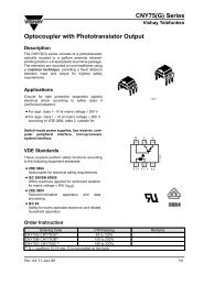
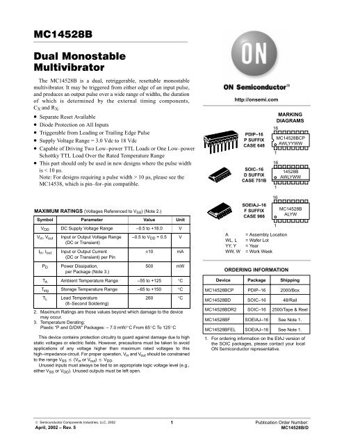
The <strong>MC14528B</strong> is a dual, retriggerable, resettable monostablemultivibrator. It may be triggered from either edge of an input pulse,and produces an output pulse over a wide range of widths, the durationof which is determined by the external timing components,C X and R X .• Separate Reset Available• Diode Protection on All Inputs• Triggerable from Leading or Trailing Edge Pulse• Supply Voltage Range = 3.0 Vdc to 18 Vdc• Capable of Driving Two Low–power TTL Loads or One Low–powerSchottky TTL Load Over the Rated Temperature Range• This part should only be used in new designs where the pulse widthis < 10 s.Note: For designs requiring a pulse width > 10 s, please see theMC14538, which is pin–for–pin compatible.MAXIMUM RATINGS (Voltages Referenced to V SS ) (Note 2.)Symbol Parameter Value UnitV DD DC Supply Voltage Range –0.5 to +18.0 VV in , V out Input or Output Voltage Range(DC or Transient)–0.5 to V DD + 0.5 VI in , I outP DInput or Output Current(DC or Transient) per PinPower Dissipation,per Package (Note 3.)±10 mA500 mWT A Ambient Temperature Range –55 to +125 °CT stg Storage Temperature Range –65 to +150 °CT LLead Temperature(8–Second Soldering)260 °C2. Maximum Ratings are those values beyond which damage to the devicemay occur.3. Temperature Derating:Plastic “P and D/DW” Packages: – 7.0 mW/C From 65C To 125CThis device contains protection circuitry to guard against damage due to highstatic voltages or electric fields. However, precautions must be taken to avoidapplications of any voltage higher than maximum rated voltages to thishigh–impedance circuit. For proper operation, V in and V out should be constrainedto the range V SS (V in or V out ) V DD .Unused inputs must always be tied to an appropriate logic voltage level (e.g.,either V SS or V DD ). Unused outputs must be left open.AWL, LYY, YWW, Whttp://onsemi.comPDIP–16P SUFFIXCASE 648SOIC–16D SUFFIXCASE 751BSOEIAJ–16F SUFFIXCASE 966= Assembly Location= Wafer Lot= Year= Work WeekORDERING INFORMATIONMARKINGDIAGRAMSDevice Package Shipping<strong>MC14528B</strong>CP PDIP–16 2000/Box<strong>MC14528B</strong>D SOIC–16 48/Rail<strong>MC14528B</strong>DR2 SOIC–16 2500/Tape & Reel1. For ordering information on the EIAJ version ofthe SOIC packages, please contact your localON Semiconductor representative.161161161<strong>MC14528B</strong>CPAWLYYWW14528BAWLYWW<strong>MC14528B</strong>ALYW<strong>MC14528B</strong>F SOEIAJ–16 See Note 1.<strong>MC14528B</strong>FEL SOEIAJ–16 See Note 1.© Semiconductor Components Industries, LLC, 2002April, 2002 – Rev. 51 Publication Order Number:<strong>MC14528B</strong>/D
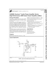
<strong>MC14528B</strong>PIN ASSIGNMENT BLOCK DIAGRAM ONE–SHOT SELECTION GUIDE http://onsemi.com2
<strong>MC14528B</strong>ELECTRICAL CHARACTERISTICS (Voltages Referenced to V SS )ÎÎÎÎÎÎÎÎÎÎÎÎÎÎÎÎÎÎÎÎÎÎÎÎÎÎÎÎÎÎÎÎÎÎÎÎÎÎÎÎÎÎÎÎÎÎÎÎÎÎÎÎÎÎÎÎÎÎÎÎÎÎÎÎÎÎCharacteristicOutput VoltageV in = V DD or 0“0” LevelSymbolV OL 5.01015V 5.0“1” LevelV in = 0 or V DDOH1015Input Voltage“0” Level(V O = 4.5 or 0.5 Vdc)(V O = 9.0 or 1.0 Vdc)(V O = 13.5 or 1.5 Vdc)(V O = 0.5 or 4.5 Vdc)(V O = 1.0 or 9.0 Vdc)(V O = 1.5 or 13.5 Vdc)“1” LevelOutput Drive Current(V OH = 2.5 Vdc) Source(V OH = 4.6 Vdc)(V OH = 9.5 Vdc)(V OH = 13.5 Vdc)(V OL = 0.4 Vdc) Sink(V OL = 0.5 Vdc)(V OL = 1.5 Vdc)V IL5.01015V IH5.01015I OH5.05.01015I OL5.01015V – 55C 25C 125CDDVdc Min Max Min Typ (4.) Max Min Max Unit———4.959.9514.95———3.57.011– 1.2– 0.64– 1.6– 4.20.641.64.20.050.050.05———1.53.04.0——————————4.959.9514.95———3.57.011– 1.0– 0.51– 1.3– 3.40005.010152.254.506.752.755.508.25– 1.7– 0.88– 2.25– 8.80.050.050.05———1.53.04.0——————————4.959.9514.95———3.57.011– 0.7– 0.36– 0.9– 2.4Input Current I in 15 — ± 0.1 — ±0.00001 ± 0.1 — ± 1.0 µAdcInput Capacitance(V in = 0)———0.511.33.40.882.258.80.050.050.05C in — — — — 5.0 7.5 — — pF———0.360.92.4———1.53.04.0——————————VdcVdcVdcVdcmAdcmAdcQuiescent Current(Per Package)I DD 5.01015———5.01020———0.0050.0100.015Total Supply Current at anexternal load Capacitance (C L )and at external timingcapacitance (C X ), use theformula — (5.) I T — I T (C L , C X ) = [(C L + 0.36C X )V DD f + 2x10 –8R X C X (V –2 DD ) 2 f] x 10 –3where: I T in µA (per circuit), C L and C X in pF, R X in megohms,V DD in Vdc, f in kHz is input frequency.4. Data labelled “Typ” is not to be used for design purposes but is intended as an indication of the IC’s potential performance.5. The formulas given are for the typical characteristics only at 25C.5.01020———150300600µAdcµAdchttp://onsemi.com3
<strong>MC14528B</strong>SWITCHING CHARACTERISTICS (8.) (C L = 50 pF, T A = 25C)CharacteristicOutput Rise and Fall Timet TLH , t THL = (1.5 ns/pF) C L + 25 nst TLH , t THL = (0.75 ns/pF) C L + 12.5 nst TLH , t THL = (0.55 ns/pF) C L + 9.5 nsTurn–Off, Turn–On Delay Time — A or B to Q or Qt PLH , t PHL = (1.7 ns/pF) C L + 240 nst PLH , t PHL = (0.66 ns/pF) C L + 87 nst PLH , t PHL = (0.5 ns/pF) C L + 65 nsTurn–Off, Turn–On Delay Time — A or B to Q or Qt PLH , t PHL = (1.7 ns/pF) C L + 620 nst PLH , t PHL = (0.66 ns/pF) C L + 257 nst PLH , t PHL = (0.5 ns/pF) C L + 185 nsSymbolC XpFR XkΩt TLH , — —t THLt PLH , 15 5.0t PHLt PLH , 1000 10t PHLInput Pulse Width — A or B t WH 15 5.0 5.01015Output Pulse Width — Q or Q(For C X < 0.01 µF use graph forappropriate V DD level.)V DDVdc Min Typ (9.) Max Unitns5.010155.010155.01015t WL 1000 10 5.01015t W 15 5.0 5.01015Output Pulse Width — Q or Qt W 10,000 10 5.0t W = 0.2 R X C X Ln [V DD – V SS ]) (6.) 15(For C X > 0.01 µF use formula:10Pulse Width Match between Circuits in the samepackaget1 – t2 10,000 10 5.0101515 5.0 5.0Reset Propagation Delay — Reset to Q or Q t PLH ,t PHL 10151000 10 5.01015Retrigger Time t rr 15 5.0 5.010151000 10 5.01015External Timing Resistance R X — — — 5.0 — 1000 kΩExternal Timing Capacitance C X — — — No Limits (7.) µF6. R X is in Ohms, C X is in farads, V DD and V SS in volts, PW out in seconds.7. If C X > 15 µF, Use Discharge Protection Diode D X , per Fig. 9.8. The formulas given are for the typical characteristics only at 25C.9. Data labelled “Typ” is not to be used for design purposes but is intended as an indication of the IC’s potential performance.—————————1507555——————151015—————————0000001005040325120907052902107030307030305503503003050556.08.08.032590601000300250——————20010080650240180————————————459095253535600225170—————————nsnsnsnsnsµs%nsnsnsnshttp://onsemi.com4
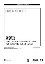
<strong>MC14528B</strong>InputsFUNCTION TABLEOutputsReset A B Q QHHLHH L Not TriggeredH H Not TriggeredH L, H, H Not TriggeredH L L, H, Not TriggeredL X X L HX X Not Triggered Figure 1. Output Source Current Test CircuitFigure 2. Output Sink Current Test Circuit ′ ′ ′′′′′ Figure 3. Power Dissipation Test Circuit and Waveformshttp://onsemi.com5
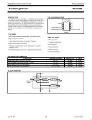
<strong>MC14528B</strong> ′ ′ INPUT CONNECTIONSCharacteristics Reset A Bt PLH , t PHL , t TLH , t THL V DD PG1 V DDt WÎÎÎÎÎÎÎÎÎÎÎÎÎÎÎÎÎÎÎÎÎÎÎÎÎÎÎÎ′′′ ′′ Figure 4. AC Test Circuitt PLH , t PHL , t TLH , t THL V DD V SS PG2t Wt PLH(R) , t PHL(R) , t W PG3 PG1 PG2*Includes capacitance of probes,wiring, and fixture parasitic.NOTE: AC test waveforms forPG1, PG2, and PG3 onnext page. Figure 6. Pulse Width versus C X Figure 5. AC Test Waveforms http://onsemi.com6
<strong>MC14528B</strong>TYPICAL APPLICATIONS Figure 7. Retriggerable<strong>Monostable</strong>s CircuitryFigure 8. Non–Retriggerable<strong>Monostable</strong>s Circuitry Figure 9. Use of a Diode to LimitPower Down Current SurgeFigure 10. Connection of Unused Sectionshttp://onsemi.com7
<strong>MC14528B</strong>PACKAGE DIMENSIONSH–A–GBFCSKD 16 PL PDIP–16P SUFFIXPLASTIC DIP PACKAGECASE 648–08ISSUE R–T– JLM http://onsemi.com8
<strong>MC14528B</strong>PACKAGE DIMENSIONS–T–G–A–D 16 PL K –B–C SOIC–16D SUFFIXPLASTIC SOIC PACKAGECASE 751B–05ISSUE JP 8 PL M R X 45JF http://onsemi.com9
<strong>MC14528B</strong>PACKAGE DIMENSIONSeZDb SOEIAJ–16F SUFFIXPLASTIC EIAJ SOIC PACKAGECASE 966–01ISSUE O L E Q 1E H E M LDETAIL PAVIEW P c A 1 http://onsemi.com10
<strong>MC14528B</strong>Noteshttp://onsemi.com11
<strong>MC14528B</strong>ON Semiconductor and are registered trademarks of Semiconductor Components Industries, LLC (SCILLC). SCILLC reserves the right to makechanges without further notice to any products herein. SCILLC makes no warranty, representation or guarantee regarding the suitability of its products for anyparticular purpose, nor does SCILLC assume any liability arising out of the application or use of any product or circuit, and specifically disclaims any and allliability, including without limitation special, consequential or incidental damages. “Typical” parameters which may be provided in SCILLC data sheets and/orspecifications can and do vary in different applications and actual performance may vary over time. All operating parameters, including “Typicals” must bevalidated for each customer application by customer’s technical experts. SCILLC does not convey any license under its patent rights nor the rights of others.SCILLC products are not designed, intended, or authorized for use as components in systems intended for surgical implant into the body, or other applicationsintended to support or sustain life, or for any other application in which the failure of the SCILLC product could create a situation where personal injury or deathmay occur. Should Buyer purchase or use SCILLC products for any such unintended or unauthorized application, Buyer shall indemnify and hold SCILLCand its officers, employees, subsidiaries, affiliates, and distributors harmless against all claims, costs, damages, and expenses, and reasonable attorney feesarising out of, directly or indirectly, any claim of personal injury or death associated with such unintended or unauthorized use, even if such claim alleges thatSCILLC was negligent regarding the design or manufacture of the part. SCILLC is an Equal Opportunity/Affirmative Action Employer.PUBLICATION ORDERING INFORMATIONLiterature Fulfillment:Literature Distribution Center for ON SemiconductorP.O. Box 5163, Denver, Colorado 80217 USAPhone: 303–675–2175 or 800–344–3860 Toll Free USA/CanadaFax: 303–675–2176 or 800–344–3867 Toll Free USA/CanadaEmail: ONlit@hibbertco.comN. American Technical Support: 800–282–9855 Toll Free USA/CanadaJAPAN: ON Semiconductor, Japan Customer Focus Center4–32–1 Nishi–Gotanda, Shinagawa–ku, Tokyo, Japan 141–0031Phone: 81–3–5740–2700Email: r14525@onsemi.comON Semiconductor Website: http://onsemi.comFor additional information, please contact your localSales Representative.http://onsemi.com12<strong>MC14528B</strong>/D