BF1,2 & 3 Swageloks® (110) - Sea Frost Refrigeration
BF1,2 & 3 Swageloks® (110) - Sea Frost Refrigeration
BF1,2 & 3 Swageloks® (110) - Sea Frost Refrigeration
You also want an ePaper? Increase the reach of your titles
YUMPU automatically turns print PDFs into web optimized ePapers that Google loves.
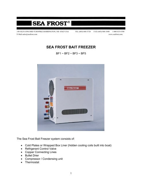
148 OLD CONCORD TURNPIKE BARRINGTON, NH 03825 USA TEL (603) 868-5720 FAX (603) 868-1040 1-800-435-6708E-Mail:sales@seafrost.comwww.seafrost.comSEA FROST BAIT FREEZER<strong>BF1</strong> ~ BF2 ~ BF3 ~ BF5The <strong>Sea</strong> <strong>Frost</strong> Bait Freezer system consists of:• Cold Plates or Wrapped Box Liner (hidden cooling coils built into boat)• Refrigerant Control Valve• Copper Connecting Lines• Bullet Drier• Compressor / Condensing unit• Thermostat1
OPERATIONWith the thermostat in the “on” position, the compressor, fan, and pump (if equipped)will operate. Ten minutes after starting the compressor the area near the valve or thetop of a hidden coil box will begin to cool and frost.If you do not observe cooling, with the compressor and fan running, switch offthe unit to avoid damage.After several hours the box temperature will cool to well below freezing.The first plate or the top section of a wrapped box will cool first. Because it freezes first,all the moisture suspended in the air within the box condenses and freezes at this plate.<strong>Frost</strong> is not a good indication of proper operation; check the temperature with athermometer. When the box and contents cool to the desired setting, the compressorand fan will cycle on and off periodically to maintain the set temperature.CONDENSING UNIT LOCATION AND MOUNTINGThe design of the Bait Freezer (BF) allows the air-cooled condensing unit to be placedin an enclosed space such as a locker or engine room.Mount the BF level with the compressor at the bottom. It may be bulkhead or platformmounted.Installation Requirements• Never block the inlet nor outlet. Service access and installation requires thatthe front and left end (inlet/outlet side) be exposed.• Provide for driest, coolest air for intake. Use standard 4" duct hose to draw airin from the cabin area to insure the coolest, driest air supply. Intake ducting fromthe exterior of the boat may cause damp salt air to be drawn in which will reduceunit life. For intake or exhaust through a finished panel, order a flange grill.• Discharge does not need ducting if a vent in the area allows warm air toescape. An un-ducted unit in a poorly ventilated small space will heat the air,lowering the capacity of the unit and possibly causing damage by overheating thecompressor.• Total combined air duct length for intake and discharge should not exceedsix feet.2
Water CoolingWater-cooling is standard on BF2 and BF3 models. Water from an air conditioningpump manifold can be plumbed into the BF condensing unit and triggered by the <strong>110</strong>-volt supply labeled "pump" or a dedicated pump can be installed. A flow of two to threeGPM is sufficient. Use of water-cooling is not mandatory; the unit will operate with aircoolingonly. If the condensing unit is mounted in a confined area with little ventilation,or in a very hot engine room, water-cooling must be used.EVAPORATOR PLATE INSTALLATIONMount the plates on opposite walls as high as possible to take advantage of thermalconvection. Install the plates with the Wellnut, spacers, and screws provided.Mount <strong>Sea</strong> <strong>Frost</strong> plates with the Wellnut holefasteners. Use a template or the plate itself tolocate the mounting holes in the box. Drill a 3/16"pilot hole and then increase this hole to 3/8". Installthe screw into the plate through the spacer thentighten the screw in the Wellnut. Push the rubbermounts into the pre-drilled holes. Tighten thescrews.Figure 1 ~ Wellnut Installation DetailSWAGELOK FITTINGSSwagelok fittings come to you completely assembled,finger-tight, and ready to use.Do not take apart the fittings before you are ready touse them; dirt can get into the fitting and cause leaks.You also risk damaging the threads of the fittings if thenuts are removed.This is a double ferrule system. The most commoninstallation problem encountered with <strong>Sea</strong> <strong>Frost</strong> is theincorrect assembly of the fittings. Assemble all fittingsas shown in figure 2.Figure 2 ~ Swagelok Fitting Assembly3
Note: Loosen the nut slightly before assembly, and then retighten with your fingersbefore tightening with a wrench. This avoids cross threading.Swagelok Installation Instructions1. Always leave two inches of straight, undistorted copper tube leading to allSwagelok fittings to allow proper connection. Measure the tubing the correctdistance from the end and mark with a pencil. Refer to Table #1.Table # 1 Scribe Line MeasurementsCopper Tubing Diameter(Inches)Measurement from the end of the tubing(Inches)3/8 11/165/16 5/81/4 9/162. Insert the marked copper tubing, into the Swagelok tube fitting body. See figure 3.The tubing should rest firmly on the shoulder of the fitting body so that the pencilmark is flush with the nut. This mark will also show that the tube has not movedbefore tightening. Tighten the nut with your fingers. As you tighten the fitting, thespace from the pencil mark to the shoulder increases.Figure 3 ~ Insert Tube into Fitting Body3. Scribe the nut at the six O’clockposition. See figure 4.4. Tighten the nut wrench snug.Wrench snug is the first point whenthe tube cannot be pulled from thefitting, (when the ferrules tightenenough to contact the tubing).5. Hold the fitting body with a back-upwrench and tighten the nut oneand-one-quarterturns (1¼) fromthe scribe mark.Figure 4 ~ Scribe Fitting at Six O’clock4
Note: Make all connections with twowrenches, do not allow the fittings to turn ortwist when tightening. Tighten Swagelokfittings to a torque spec, not infinite tightness.Be sure your starting point is wrench snug. Adistorted tube will give a false starting point.Figure 5 ~ Turn the Nut 1 ¼ TurnsReconnecting Pre-Swaged FittingsYou can disassemble and retighten Swagelok tube fittings many times.1. Insert the tubing with pre-swaged ferrules into the fitting body until the front ferruleseats.2. Tighten the nut by hand.3. Tighten approximately one-quarter turn with a wrench.EXPANSION VALVEValve Installation on a Plate SystemTrim the tube ends on the plates as necessary. Allow at least 3/4" of clean, straighttubing to insert into the Swagelok fitting.Install the valve to supply one of the 3/8” tubes from one of the plates. Either plate maybe supplied first. Position the valve to allow access to the screw cap on top of thevalve. The valve cap should be up.Connect the jumper line between the remaining tube on the first plate to either tube onthe second plate.Connect a return line to the remaining tube on the second plate; this return lineconnects to the compressor.5
Valve Installation on a Wrapped Hidden Coil SystemTrim the tube ends on the coil as necessary. Allow at least 3/4" of clean, straight tubingto insert into the Swagelok fitting. Refer to the Swagelok installation instructions onpage three.Install the valve to supply the top 5/16” tube end on the hidden coil. Position the valveto allow access to the screw cap on top of the valve. The valve cap should be up.Connect a return line to the remaining tube end; this return line connects to thecompressor.BULLET DRIERNote: Unpack and fit the drier last. This prevents moisture from saturating thedesiccant in the drier.Use the 5/16" x 1/4" Swageloks to connect the tube from the compressor to the inputside of the drier and connect the output side of the drier to the valve. Note: Arrows arestamped into the bullet direr showing flow direction.COPPER TUBE RUNSTwo copper lines connect the plates or wrapped hidden coil, and the compressor; one is3/8" and the other is 1/4".Run the 1/4" liquid line between the condensing unit and the expansion valve. You willfit the bullet drier to this line.The 3/8" suction line connects the last plate or hidden coil tube end to the suction porton the BF cabinet.Run the 1/4" liquid line in contact with the 3/8" suction line for several feet from thecabinet. Wrap these two tubes tightly together with electrical tape and insulate thissection. This will improve operation and prevent moisture from condensing on thecoldest section of these tubes. Insulating the remaining length of 3/8" return line to thecompressor is not necessary.After each cut, cap the copper tube ends with the plastic caps until you make theSwagelok connection. Support the tubing and protect from chafe.WARNING: The BF unit is shipped pressurized with nitrogen. Before removing theSwagelok caps on the connection ports, remove the plastic caps on the service valvecovers and depress the valves cores to vent any existing pressure.6
Compressor ConnectionsRemove the Swagelok caps from the liquid and suction fittings. Attach the unionbodies. This is a pre-swaged connection, which is 1/4 turn from wrench snug.Connect the 1/4" line to the condenser fitting and 5/16" line to the compressor. Tightenthese fittings 1 1/4" turns from wrench snug.Thermostat LocationThe thermostat is low voltage and is connected and powered by the transformer in thecompressor cabinet. Mount the thermostat in a convenient location where the sensingbulb will reach a mounting screw on a plate. It is necessary that the bulb of the sensorhave good thermal contact with the plate. On multiple plate installations, thethermostat must sense the last plate in the series after the valve.Thermostat location on a Wrapped Hidden Coil BoxPosition the thermostat close enough for the sensing bulb to reach the middle of thewrapped box. Attach the bulb to the box wall with marine adhesive. Do not drill into awrapped box liner for any reason.The probe temperature is displayed when <strong>110</strong>-volt power is available. The probetemperature is not the cabinet temperature. The probe temperature is always colderthan the cabinet.Thermostat Wiring - RancoThe Electronic Temperature Control operates on low voltage (24VAC) supplied by thetransformer in the compressor cabinet.A 15’ wiring harness is fitted to the thermostat. Use red, blue, and white 16-gauge wireto extend this harness if a longer length is needed. Attach the wires to the terminal stripusing #8 ring terminals, matching corresponding wire color.Thermostat Wiring – IR33The Electronic Temperature Control operates on low voltage (24VAC) supplied by thetransformer in the compressor cabinet. A 20’ 4-wire gray wiring harness is fitted to thethermostat. Attach the wires to the terminal strip terminals, following colors below. Seewiring diagram on page 7.Wires from gray harnessGreenWhite & RedBlackTerminal strip in compressor cabinetRedBlueWhite7
WiringThe Ranco Electronic Temperature Control operates on low voltage (24VAC) suppliedby the transformer in the compressor cabinet.A 15’ wiring harness is fitted to the thermostat. Use red, blue, and white 16-gauge wireto extend this harness if a longer length is needed. Attach the wires to the terminal stripusing #8 ring terminals, matching corresponding wire color.RANCO THERMOSTAT WIRINGIR33 THERMOSTAT WIRING8
<strong>110</strong>-Volt circuitA separate 15-amp breaker is required for the <strong>110</strong>-volt supply. A built in transformerpowers the thermostat circuit. For operation the BF must have <strong>110</strong>-volt power.COMMISSIONINGAttach clean, purged gauges to the suction service port on the condensing unit.Connection to the high-pressure port is not necessary when starting a new system. Thisprovides aid in fault diagnosis.1. Pressurize with nitrogen or R-134a only2. Check for leaks3. Evacuate4. Charge• This system operates with refrigerant R-134a. The proper charge (andmaximum charge) is 12 ounces.• The refrigerant may be liquid-fed into the low side after evacuation, beforethe compressor is operated.The expansion valve regulates the evaporator pressure and is adjusted to maintain aconstant evaporator pressure. The proper charge must be added before the valve canbe accurately set. Adding or increasing the charge will not raise the low side pressureand will cause overcharging.ADJUSTING THE VALVEBefore operating the compressor,unscrew the plastic cover on the valvebody to access the adjusting knob.Counter-clockwise rotation decreases thepressure. Clockwise rotation increasesthe pressure. One turn should equal a 2psi pressure change. Check that thevalve is set with the threads of theadjusting knob close to the end of thevalve body.9
Start the compressor. The valve must be adjusted to a 0 to 4 psi reading on the lowside gauge port. Be sure your gauge is set at O before hook-up. Allow several minutesbetween each adjustment. Replace the cap after each adjustment to prevent moisturefrom forming on the adjusting knob; the moisture will freeze and cause the valve tomalfunction. The valve must be dry before final cap replacement. Operate for 30minutes to confirm proper valve setting and operation.To clear the valve of dirt or chips if adjustment is not possible, turn the valve adjustmentknob clockwise about 3 turns momentarily, and then back to the proper setting while thecompressor is running. Do not leave the valve in the open position, which causes highbackpressure and may cause the compressor to overload.After satisfactory adjustment turn off the thermostat. Wait until the pressure equalizeson both gauges before you disconnect the gauges and then recap the service ports.When the valve is dry, insulate the valve body with a piece of insulating sleeve andwrap it with cork tape; this will prevent condensation. Insulating the valve is notnecessary if it is in the box. The constant pressure valve sets the refrigerant boilingpoint and the pressure setting will indicate the minimum temperature that the BF systemcan obtain. Set the valve pressure at the lowest possible pressure setting that will coolthe box. Problems occur when the pressure is high and the thermostat is set low; thethermostat will not be satisfied.READING THE SIGHT GLASSWith the compressor operating, a clear sight glass indicates a sufficiently chargedsystem. To determine the meaning of "clear", view the sight glass when the system isoff. This is a "clear" glass.WARNING: A clear sight glass can also indicate a completely empty system.Anytime the compressor is started, white foam should appear in the sight glassindicating the presence of refrigerant. The foam may disappear quickly. If foam isobserved and the system is not cooling, the system is empty. Do not operate thesystem in this empty condition. Operation in this mode will ruin the compressor. Turnoff the main breaker to the control panel until the system can be properly leak testedand recharged.Fast moving white foam with the compressor operating indicates an insufficient chargelevel. Watch closely for a transition from foam to total liquid, (indicated by a clear sightglass). This transition point can be missed if not given proper attention. The sight glassmay show large bubbles even when the charge is sufficient, so it is important todifferentiate between "foam" and "bubbles". The foam condition has velocity anddirection; the bubbles are large, temporary, and nearly stationary. Do not try to chaseaway these larger bubbles with more refrigerant; overcharging will occur. Air in thesystem may give a false sight glass reading, which could lead to overcharging. If in10
doubt, discharge a suspected overcharged system to continuous foam and slowly addrefrigerant to clear the glass. Monitor the sight glass continually. In a warm system,when the cabinet is above freezing (32.F) upon start-up, the sight glass may takeseveral minutes to clear. A cold cabinet may show a clear glass within seconds of startup.SIGHT GLASS DETAILClear or Empty Stationary Bubbles Foam (Low Charge)Troubleshooting note: The operating pressure of the system will not indicate theamount of refrigerant in the system. The valve will not give proper operation orpressure if it is undercharged. Check the valve scribe line. It should correlate to gaugepressure.The system requires enough refrigerant to supply liquid to the valve. If the valve has asteady hissing sound then the charge is sufficient. If the valve is sputtering then it islow. If the valve is making a noticeable roar it is empty. If the low side pressure isproperly set the high side pressure will be 80 to 135 psi depending on the airtemperature (50 to 95 degrees F.) at the unit. Upon start up the valve body will begin tofrost.THERMOSTAT OPERATIONThe thermostat is pre-set and locked at the factory. When locked the keypad isdisabled and changes to the settings cannot be made. To change the settings thelockout switch must be placed in the unlock position.To access the lockout switch:1. Switch off the power.2. Remove the four screws and cover.3. Slide the lockout switch to the right to the unlock position.4. Replace the cover.5. Re-power the system.6. To program refer to table # 2.11
Step Display Description1 F or C Fahrenheit or Celsius ScalePress the set key once to access the Fahrenheit / Celsiusscale. The display will show the current status, either F fordegrees Fahrenheit or C for degrees Celsius. Thethermostat has been pre-set at the factory for Fahrenheit.Press the up or down arrow key to choose between the Fand C.2 S1 (blinking) Setpoint TemperaturePress the set key again to access the setpoint. The displaywill show the current set point. The setpoint has been presetto 0 degrees F. Press either the up or down arrow keyto change the setpoint to the desired temperature.3 DIF 1 (blinking) Differential TemperaturePress the set key again to access the differential. Thedisplay will show the current differential. The differentialtemperature has been pre-set at 5 degrees F. Press eitherthe up or down arrow key to increase or decrease thedifferential setting.4 C1 / H1 Cooling or Heating ModePress the set key again to access the heating or coolingmode. The display will show the current mode. C1 forcooling or H1 for heating. The Thermostat has been presetfor C1. Do not change this setting. The BF does notwork in heat mode. Press the set key once more andprogramming is complete.Note: Pressing the set key accepts the setting and brings you to the next step. Youmust push the set key through all steps to return to the temperature display to allow thecompressor to operate.Refer to separate manual for operation of IR33 Electronic thermostat.DEFROSTINGThe unit will require defrosting as the frost layer builds up. You can defrost the platesusing several methods:• Allow the plates to warm above freezing.• Pour warm water over the plates.• Heat the plates with a hair dryer.• Scrape the plates with a spatula or ice scraper to remove excessive frost build up.12
TROUBLESHOOTINGThe low side operating pressure of the system will not indicate the amount ofrefrigerant in the system. The valve will not give proper operation or pressure if it isundercharged. Check the valve scribe line. It should correlate to gauge pressure.The system requires enough refrigerant to supply liquid to the valve. If the valve has asteady hissing sound then the charge is ok. If the valve is sputtering then it is low. Ifthe valve is making a noticeable roar it is empty. If the low side pressure is properly setthe high side pressure will be 80 to 135 psi depending on the air temperature (50 to 95degrees F.) at the unit. Almost immediately upon start up the valve body will begin tofrost.Bait Freezer SpecificationsBF 1 BF 2 BF 3 BF 5Amp Start (LR) 28 28 30 38A.C. amp draw 3.8 @ <strong>110</strong> volts 3.8 @ <strong>110</strong> volts 4 @ <strong>110</strong> volts 5-9Horsepower 1/4 1/4 3/8 1/2BTU per hour 760 @ -10 F. 760 @ -10 F. 930 @ -10 F. 1400 @ -10 F.Height 16" 16" 16" 16"Width 14.5" 14.5" 14.5" 14.5"Depth 7.5" 7.5" 7.5" 7.5"CoolingDucted AirCooledDucted Air andWater Cooled(remote waterpump required)Ducted Air andWater Cooled(remote waterpump required)Compressorunit weight36 lbs 38 lbs 42 lbs 49 lbsRefrigerant 134a 134a 134a 134aDucted Air andWater Cooled(remote waterpump required)13
BAIT FREEZER WITH WRAPPED BOX LAYOUT14
Figure 9 ~ Wrapped Box LayoutBAIT FREEZER WITH PLATES LAYOUT15
Figure 10 ~ Plate Layout16


