SA 3 134a - Sea Frost Refrigeration
SA 3 134a - Sea Frost Refrigeration
SA 3 134a - Sea Frost Refrigeration

You also want an ePaper? Increase the reach of your titles
YUMPU automatically turns print PDFs into web optimized ePapers that Google loves.
148 OLD CONCORD TURNPIKE BARRINGTON, NH 03825 U<strong>SA</strong> TEL (603) 868-5720 FAX (603) 868-1040 1-800-435-6708E-Mail:sales@seafrost.comwww.seafrost.comOPERATION & INSTALLATIONINSTRUCTIONS<strong>SA</strong>-III (134A) SeriesSEA FROST148 OLD CONCORD TURNPIKEBARRINGTON, NH 03825U.S.A.(603) 868-5720<strong>Sea</strong><strong>Frost</strong> is a registered trademark of C.F. Horton & Co., IncAspects of the SEA FROST design are covered byUS Patent # 4,356,708Revised 12/01Copyright © 1993 by C.F. Horton & Co., Inc.
CONTENTS<strong>SA</strong>-III OPERATION 3ICE MAKING 4MAINTENANCE 5-6INSTALLATION 7-8SWAGELOK FITTINGS 9-11INSTALLATION INSTRUCTIONS 12VALVE UNIT 13RECEIVER FILTER DRYER (RFD) 13-14THERMOSTAT & WIRING 14-15REFRIGERANT HANDLING 16GAUGES 18LEAK CHECKING 21-22NEW SYSTEM CHARGING 23-24CHECKING THE CHARGE/ADDING CHARGE 26TROUBLESHOOTING 27-29WATER CIRCUIT DWG 30<strong>SA</strong>-III LAYOUT DWG 312
<strong>SA</strong>-III OPERATIONThe SEAFROST <strong>SA</strong>-III system is an electrically driven refrigeration plant. Operationof the compressor will freeze the contents of the holdover plates in the boat's iceboxproviding refrigeration by cold holdover for an extended period after the compressor hasbeen turned off. A boat without continuous power can benefit from this by operating theSEA FROST <strong>SA</strong>-III system when the generator plant is operated. Operation time willvary with each boat.A little time-spent learning about your system and some experimentation will beadvantageous. Maximum holdover will be reached when the cabinet is at the desiredtemperature and the holdover plates are frozen. Running times beyond this have noadvantage other than to delay warming the plates.The <strong>SA</strong>-III is water-cooled. Water should begin to flow from the discharge at thesame time the unit starts. Be sure the water is flowing. If no water flows, stop thesystem and inspect the water pump and strainer for obstructions. (See troubleshooting and maintenance sections.)After starting a warm system check the holdover devices for a temperature drop. If atemperature drop is not indicated, stop the unit and read Checking The Charge andReading The Sight Glass.CONTROLSThe <strong>SA</strong>-III thermostat control is labeled with off, one, two, and three snowflakes.When the boat’s breaker panel is switched on and 110-volt power is available, turningthe knob from "off" to one snowflake will start the compressor. Turning the knob tothree snowflakes will increase the time the compressor operates, making thetemperature cooler. Experiment with the control position to obtain the best setting.3
ICE MAKINGYour SEA FROST holdover plates may be equipped with vertical ice trays. The icetrays are held in contact with the plates by a stainless steel rod.Fill the vertical trays with water and hang them on the face of the plate. Try to get somewater between the tray and the plate surface to increase the thermal contact (increasingfreezing ability).HARVESTING ICEPlan to wait some time after the trays are frozen for them to thaw in a sink or away fromthe plate in the refrigerator. When the outside surface is wet invert the tray and let theice slide out.STORAGE OF ICE CUBE<strong>SA</strong>fter ice has been made and harvested, store it in resealable plastic bags in therefrigerator or is so equipped in the freezer. Ice trays left in contact with the plate willmelt rapidly if the plate goes above freezing.DEFROSTINGIt is important to defrost the holdover plates regularly. This will maximize the efficiencyof the system and ice making performance. It is not necessary to turn off the system todefrost. Scrape off any frost with a piece of wood or galley utensil. A noticeable drop inthe cabinet temperature will occur.BAG STYLE ICE MAKINGIf your SEA FROST system is not equipped with the vertical tray kit, you can still makeice. One method is to use zip lock bags. When filled with water, a clip binder or aclamp of your own invention can hold the bag in contact with the plate.4
It is IMPORTANT that NO WATER flows between the plastic housing and the pumpbody. The screws that hold the cover also seal the housing. Water behind the housingwill ruin the motor bearings. BE SURE THE PUMP HOUSING IS ABSOLUTELY DRYBEFORE DI<strong>SA</strong>SSEMBLY.Remove the screws holding the inlet fitting plate (larger hose size). The impeller maybe removed with its ceramic seal and thrust washer. Reassemble in the reverse order.An exploded diagram is in this manual. Observe the "O" ring that seals the housingcover plate. Make sure they are in good condition. Open the seacock and Inspect forleaks.NEVER OPERATE THE PUMP WHILE DRY. IF IT IS SUSPECTED THAT THISCONDITION HAS OCCURRED, INSPECT THE IMPELLER AND HOUSING FORWEAR.CHECKING THE REFRIGERANT CHARGEThe <strong>SA</strong>-III system is fitted with a sight glass located in the top of the RFD. Thecharge level should be inspected to be sure refrigerant is of the proper amount and thatthere are no slow leaks. Switch the unit on and immediately inspect the sight glass.A high velocity white foam should be observed and after a minute or two show a blackor clear condition. A clear glass and an empty glass will look the same. A transitionmust be seen to be sure refrigerant is present. Do not operate a low or empty system.See the Leak Checking and Adding Charge sections.LAY-UP (WINTERIZING)Flush the pump and condenser with plenty of fresh water. Pressure water should beflushed through the inlet side of the water pump. In freezing climates Anti-freeze shouldbe pumped through, after flushing, by operating the system for a very brief period.Connect a short hose to the suction side of the pump to draw from a bucket. Run thepump (switch on unit) until antifreeze is pumped through the seawater circuit. Thepump is not self-priming and may require filling the hose and pump with a funnel. DONOT RUN THE PUMP DRY. It is water lubricated.6
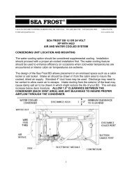
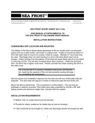
INSTALLATIONWORK HABITSInstaller's care should be stressed. No matter how good SEAFROST equipment is, itsperformance and life are in the hands of the installer. To insure your work:1. Read this manual.2. Reread any aspect you don't understand.3. Follow Swagelok fitting instructions carefully.4. Spend enough time leak checking to be sure there are no leaks.5. Thanks from all of us who have to guarantee your work.There are two contaminants that will give you problems in any refrigeration system.They are WATER and DIRT. Moisture is always present and cannot be eliminated,water in this case refers to puddles and drops. Dirt is any solid. The installer's habitswill be most important in ensuring a trouble-free start-up. We have added a largereceiver filter dryer (RFD) to take care of all dirt and moisture that might get into thesystem during a careful installation. Moisture in the system is boiled off when thesystem is evacuated, or it is captured in the desiccant. There is a screen in theexpansion valve to prevent dirt from plugging it.Excess moisture that the RFD can't handle will plug the expansion valve with ice. Thisice stops the cycle. The only cure is to discharge the refrigerant, replace the RFD, reevacuatethe system, and recharge it. This remedy takes time and is somewhat costly.Keep the system clean when installing it to save time for something more fun.TUBE HANDLINGInstallation is quite simple. All the copper tube comes to you with the ends caped. Anyrouting of the tube must be done with the tube either taped or capped. Cap both tubeends after each cut. (Spare caps have been included).Work with only one line at a time, and only uncap one end at a time.7
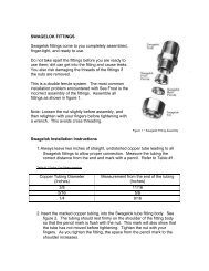
NOTES ON SWAGELOK FITTINGSSwagelok fittings come to you completely assembled, finger tight. (Pieces a, b, and c inDrawing #1 are already together). They are ready for immediate use.Disassembly before use can result in dirt and foreign material getting into the fitting andcausing leaks. If disassembly is necessary, reassemble per drawing.This is double ferrule system. The most serious installation problem encountered withSEA FROST is the incorrect assembly of these fittings. Be absolutely sure that youassemble all fittings as in Drawing #1.To ease assembly slacken the fitting nut slightly before pushing onto the tube, thenretighten with fingers before tightening with a wrench. (This is to avoid cross threading.)Step 1. Always leave two inches of straight, undistorted tubing leading to all Swagelokfittings to allow proper connection.Step 2. Prior to inserting 3/8" tubing into Swagelok tube fitting, make a pencil mark 3/4"from end of tube as a guide. Prior to inserting 1/4" tubing, make a pencil mark 5/8" fromthe end of the tube as a guide.Step 3. Insert clean, smooth tubing with the pencil mark into the Swagelok tube fitting.You can be sure the tube is resting firmly on the shoulder of the fitting when the pencilmark is flush with the nut.Step 4. Tighten the Swagelok nut to a wrench snug* position. Scribe the nut with apencil at the 6:00 o'clock position (see drawing, step # 2).* Wrench snug is the first point in the assembly tightening when the tube cannot bepulled from the fitting, (when the ferrules tighten enough to contact the tubing).Step 5. Now, while holding the fitting body with a back-up wrench, tighten the nut oneand-one-quarterturns (1+1/4). To do so watch the scribe mark, make one completerevolution, and continue to the 9:00 o'clock position. (See drawing, step #3).9
Drawing 1STEP 1Simply insert the tubing into the Swageloktube fitting. Make sure that the tubing restfirmly on the shoulder of the fitting and thatthe nut is wrench snug.STEP 2Before tightening the Swagelok nut, scribethe nut at the six o’clock position.STEP 3Now, while holding the fitting body steadywith a backup wrench, tighten the nut 1 ¼turns. Watch the scribe mark, make onecomplete revolution and continue to the 9o’clock position. By scribing the nut at 6o’clock position as it appears to you, therewill be no doubt as to the starting position.When tightened 1 ¼ turns to the 9 o’clockposition you can easily see that the fittinghas been properly installed.10
* SWAGELOK FITTINGS ARE TO BE TIGHTENED TO A TORQUE SPEC, NOTINFINITE TIGHTNESS. BE SURE YOUR STARTING POINT IS WRENCH SNUG.(SEE STEP 4 IN THE SWAGELOK ASSEMBLY INSTRUCTIONS.) A DISTORTEDTUBE MIGHT GIVE A FALSE STARTING POINT.* Swagelok fittings have a built-in spring interaction between the ferrules. Thiscompensates for temperature changes and allows the fittings to be reconnected manytimes. As the fitting is tightened, a burnishing occurs between the body of the fitting andthe ferrules and between the ferrules and the tube. This action provides the tightestconnection available.* When making all connections, USE TWO WRENCHES. Don't allow the fittings to turnor twist when tightening.RECONNECTING PRE-SWAGED FITTINGSConnections can be disconnected and retightened many times.When reconnecting, insert the tubing with pre-swaged ferrules into the fitting until thefront ferrule seats in the fitting. Tighten the nut by hand. Tighten the nut one-quarter ofa turn with a wrench (or to original one-and-one-quarter tight position). Then snugslightly with the wrench. No more than an additional 1/8 turn.11
VALVE UNITFor appearance and convenience of installation, the valve control unit (V/U) may mountoutside the icebox. The valve will attract moisture and drip if it is not well insulated withthe valve blanket and additional insulation. Insulate the valve after installation and leakchecking. In certain applications it may be necessary and easier to mount the valveinside the cabinet. Refer to schematic drawings when connecting more than one plate.Before cutting the tubing:1. Leave a minimum of one inch of tube beyond a bulkhead.2. Allow room for wrench access.- 90-degree elbows can be installed on the valve unit to reduce space requirements ifnecessary.- The tubing will support the valve unit.- The tubing must bottom in the fitting. Refer to the Swagelok assembly instructions.Working with one line at a time, remove the Swagelok caps from compressor andcondenser. Attach union fitting bodies. Make up 1/4 turn from wrench snug. (This is apre-Swaged connection.RECEIVER FILTER DRIER (RFD)LOCATION: The RFD is fitted with a sight glass in the top portion. Be sure that it canbe viewed when mounted in an upright position (the sight glass is on the top). The RFDmay be supported by the tubing or secured with a large tie wrap.Because the RFD contains desiccant to absorb moisture and the absorption islimited, it is important to unpack and install it after all other connections aremade. Leaving the RFD installed on a partially open system may reduce itscapacity by allowing it to absorb moisture in free air before the system is sealed.13
The RFD is a reservoir for excessrefrigerant. The RFD also contains a sightglass in the top. (Please refer to theplanning section regarding location and"readability" of the sight glass) A pick-uptube extends from the bottom of thecanister to the outlet. For proper functionof the reservoir, the RFD must bepositioned as close to VERTICAL aspossible to ensure proper operation atvarious heel angles.RUNNING THE TUBINGA 1/4" copper tube runs between the condensing unit and the RFD. Continue with 1/4"to the expansion valve.A 3/8" line connects the valve unit to the compressor.If possible run the 1/4" liquid line in contact with the 3/8" suction line.Support the tubing (every 12 to 18 inches) as necessary with tie wraps after leakchecking and insulating.THERMOSTATFor the best looking job the thermostat should be cut into a panel. (We do notrecommend installation in the insulation or in the box, as the control is not moistureprotected.) A cutting template is provided. Locate the thermostat close enough for the"bulb" tube to reach. It is only necessary that the bulb end of the sensing tube beinstalled on the plate. Use one of the mount screws for attaching the stainless clip onthe plate. The sensing tube is hollow and filled with refrigerant; avoid bending it, whichcould cause it to crack and leak. Secure any excess capillary tube in a coil inside therefrigerated cabinet. Do not allow the capillary tube to contact any of the copper lines.14
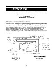
THERMOSTAT WIRINGThe thermostat electrical leads are low voltage for safety. Connect the red thermostatwires to the red wires exiting the condensing unit.110-VOLT CIRCUITA separate 15-amp breaker is required for the 110-volt circuit. The Shore Assist isprovided with a 3 wire male plug. A standard outlet mounted next to the unit isrecommended. Secure all wiring as necessary. We recommend following ABYCguidelines for wire specifications and proper procedures.PUMP INSTALLATIONProper pump installation is important for pump operation. The <strong>SA</strong>-III uses a centrifugalpump, which is not self-priming. Air pockets caused by loops or descending lines fromone component to the other may cause pump problems. The pump is water cooled andlubricated; it must never be run dry doing so will destroy the pump. A separate throughhull fitting 3/4" or larger should be used. It should be as low in the boat as possible andaway from head and cockpit drains. A forward facing scoop will prevent problems if theunit is operating underway.A large seawater strainer should be mounted above the seacock.The pump should be mounted horizontally and should be higher than the strainer. Thedischarge should be on the top. Refer to the drawing at the back of this manual.WIRING THE PUMPA three-prong plug to the compressor unit connects the pump. Be sure this plugcannot get wet.15
REFRIGERANT HANDLING AND <strong>SA</strong>FETYDo not proceed with any aspect of a procedure if you do not fully understand theprocedure and know what results to expect. Understand fully that pressure exists inrefrigeration systems. Be careful.REFRIGERANTSEA FROST is charged with REFRIGERANT-<strong>134a</strong>. R-<strong>134a</strong> is a chemical compoundcalled tetrafloroethane. It is almost odorless. Its boiling point is -15. degrees F. at sealevel. R-<strong>134a</strong> is heavier than air and it's label and container color is light blue.GENERAL <strong>SA</strong>FETY THIS IS IMPORTANT. READ THIS!R-<strong>134a</strong> is safe if handled properly. Avoid breathing vapors and prolonged skinexposure. Avoid using in areas of open flames. The vapor is heavier than air and mayreduce oxygen available for breathing. Use with sufficient ventilation to keep exposurebelow recommended limits. Do not mix with air for leak testing or use with air forany purpose above atmospheric pressure. Liquid R-<strong>134a</strong> will freeze skin. It'sespecially dangerous to the irreparable tissues of the eyes.--WEAR EYE PROTECTION--YOU WOULD BE A LOUSY BLIND MUSICIAN.Do not pressurize an empty system with R-<strong>134a</strong> without first evacuating thesystem with a vacuum pump.WARNING. DANGER. NEVER OPERATE A SYSTEM WITH THE HIGH SIDE(DISCHARGE) OPEN TO the REFRIGERANT SUPPLY. PRESSURIZATION OF THEREFRIGERANT SUPPLY COULD CAUSE IT TO BURST.16
PROCEDURES FOR WORKING WITH R-<strong>134a</strong>1) A new uncharged system must be evacuated before adding R-<strong>134a</strong>.2) An R-<strong>134a</strong> system must only be pressurized with R-<strong>134a</strong> or nitrogen.3) Only service tools dedicated to R-<strong>134a</strong> are to be used. No parts, tubing, fittings,receivers, driers, service gauges, or any refrigerant carrying components may be fittedto a R-<strong>134a</strong> system from a used system or from a CFC based system. Damage causedby the use of parts not supplied by <strong>Sea</strong> <strong>Frost</strong> for a R-<strong>134a</strong> system will cancel all claimsagainst <strong>Sea</strong> <strong>Frost</strong>.4) No oil is to be added to the <strong>SA</strong>-III system but the polyoester oil supplied by <strong>Sea</strong><strong>Frost</strong>, labeled and capped for <strong>SA</strong>-III use. No oil is to be added to a system with out priorconsultation with <strong>Sea</strong> <strong>Frost</strong>.5) The oils used in R-<strong>134a</strong> systems are extremely moisture sensitive (hydroscopic).Do not leave any tube end or component connection open to air while assembling thesystem. Be sure to use only new-capped copper tubing and be sure to cap the copperoil after cutting it.17
ACCESS TO THE SYSTEM: SERVICE PORTSThe service ports are two small-capped valves mounted on the <strong>SA</strong>-III compressor. Theports are different sizes. The blue smaller fitting on the left is the suction port. The redlarger port on the right is the discharge. These ports are the service access to thesystem and are covered with plastic caps. Without the caps the valves may leak. Toaccess these valves the proper R-<strong>134a</strong> service valve must be used.Be sure the caps are installed tightly after charging or service.NOTE: THIS SYSTEM IS CHARGED WITH R-<strong>134a</strong>. IT MUST BE CHARGED WITHR-<strong>134a</strong> ONLY. ONLY DEDICATED R-<strong>134a</strong> GAUGES AND EQUIPMENT ARE TO BEUSED. ANY CONTAMINATION FROM CFC BASED REFRIGERANTS WILLDESTROY THIS SYSTEM.GAUGESGauges must be used in the evacuation and charging. They will provide information onthe operation of the system when troubleshooting.A gauge sets consist of two gauges installed in a manifold with two valves and hoses toconnect the gauges to the system. The left gauge (blue) is a compound device; itindicates pressure and also vacuum. The right gauge (red) indicates pressure only.The valves open a center port (yellow) to the left or right side respectively. Operation ofthe valves is only necessary when moving refrigerant or evacuating. With the valvesclosed, the gauges read the pressures of the connection points. At the end of the redand blue service hoses are R-<strong>134a</strong> service port access fittings.18
R-<strong>134a</strong> SERVICE PORT ACCESS FITTINGSThe R-<strong>134a</strong> service port access fittings on the gauge hose ends are quick connectfittings with a specially designed valve that opens the hose end valve while opening thesystem service port valve.CONNECTING GAUGESTo connect these fittings to the system service port remove the protective sealing capson the service ports. See Access to the System. Note that the ports are of differentsizes. The larger diameter port is the discharge side and the smaller port is the suctionside. Pull back the collar on the access fitting valve and push it over the appropriatesystem access port. Turn the access fitting valve clockwise to open the valves. Whenyou see the manifold gauge pressure change you have access to the system.Continuing to turn the access fitting valve clockwise may damage the service port.When you see the manifold gauge pressure change you have access to the system.Continuing to turn the access-fitting valve clockwise may damage the service port.During the service operation these valves are left open. Control of refrigerant andvacuum is by the manifold hand wheels.VENTING THE GAUGE SET ~ TO ATTACH TO A CHARGED SYSTEMIf the gauge set is not fitted with sealing valves or has not been purged with refrigerant,vent the hoses for a few seconds by slacking the connections at the manifold body afterconnecting to a charged system. This will prevent air from entering the system throughthe suction port.DISCONNECTING GAUGESTo disconnecting the gauge set after running the system, turn off the dischargeservice port access fitting first. Disconnect the discharge service valve and re-cap theport on the service port block. With the center port on the gauge set turned off at therefrigerant supply both hand wheels on the gauge set may be opened and thecompressor operated to extract the refrigerant from the gauges. When the pressure inboth gauges drops to the low side operating pressure turn off the gauge valves and thesuction service valve. Turn off the compressor. Remove the suction service valve andre-cap the service port. (This procedure will remove excess refrigerant from the gaugespreventing an excessive discharge of refrigerant on the next job.)19
Disconnecting the gauge set on a static system may be done by turning off theservice valves and disconnecting them from the service ports on the service port block.Re-cap the service ports.Refer to the gauge drawing on page 18.Adding charge to a working system should be done through the suction side (blue)vapor. (See section on Safety.) The center hose is connected to the can tap. Be sureto vent the hoses to displace any air that might be in them. Keep your gauges clean.Inspect the rubber gaskets and "O" rings on the hose ends, leak check gauge valvepacking and all hose connections.Check and reset the "O" on the low side gauge, if necessary.VENTING THE CHARGE HOSE ~ WHEN ATTACHING GAUGES TO A CHARGEDSYSTEMThis procedure will vary with the type of gauges being used. This section will not applyto gauges fitted with valves in the hose ends.To avoid pulling air or other contaminants into the system, it is necessary to vent the airout of the hoses that are used to carry R-<strong>134a</strong> into the system. To vent the hose, openthe can tap valve with the can upright (vapor) then open the service valve to allow somevapor to escape. Make the connection as this vapor is escaping. Follow this procedurewhen adding refrigerant to an evacuated system or to a system low on charge.TAPPING A CAN OF REFRIGERANTBe sure the can of R-<strong>134a</strong> is clean and dry. Any contaminants on the top of the can orin the hose will enter the system. First, screw the tap assembly on the top of the can.Next, screw the valve wheel into the valve body, closing the valve. The metal point willprotrude from the gasket, but it will make its own seal while piercing the can. Be certainthat the gasket is present and is smooth and elastic. The can is now tapped.LIQUID OR VAPORRefrigerant is either a vapor or liquid. To supply vapor to a system, keep the refrigerantcan in the upright position. To supply liquid to the system, invert the can, valve down.Be sure the can is handled carefully to ensure the correct refrigerant condition issupplied.20
CHANGING CANSThe compressor should be turned off while changing cans. Close the valve on theempty can. Unscrew the can from the valve body. Some pressure may be present. Letthis drop before completely removing the can tap. Switch the tap to the other can, andrethread onto the can.COMMISSIONING PROCEDUREEVACUATION WITH A VACUUM PUMPEvacuation removes air, readying the system for charging.Connect a gauge set to the service ports. Connect the gauge center hose to a highvacuum pump. Start the pump and slowly open the low side/suction gauge hand wheel.As the vacuum drops below 20 inches open both hand wheels fully.EVACUATION LEAK TESTEvacuate the system to the best vacuum (lowest pressure). As the gauge reaches thislow pressure close the valves to the pump. Observe the vacuum gauge and be sure thepressure remains constant for 5 minutes. If the pressure rises rapidly check all theconnections again. Re-evacuate to the lowest pressure and test by holding a vacuumwith the gauges closed. Be sure the system will hold this vacuum. Proceed by openingthe valves and continuing the evacuation process for 30 minutes more. A micron gaugecan be used to measure vacuum. Proper dehydration and evacuation should be on therange of 200 to 500 microns.The evacuation leak check is a preliminary check and is not to be considered a systemleak check.NEW SYSTEM CHARGINGINTRODUCING INITIAL CHARGEAfter the evacuation leak test and pump down, shut off the manifold valves, disconnectthe center hose from the pump and connect it to a can of refrigerant. Vent the hosefrom can tap (refrigerant supply) to the manifold. With the refrigerant can in the inverted(liquid) position, open the discharge side valve (high side) valve and feed in about a 1/2a can of refrigerant (6 to 8 ounces). Close the valve and begin an inspection of all theconnections in the system.21
LEAK CHECKINGLeak checking is a very important step, which should be done with diligence. A leak willcripple this system. Please take the time needed to be sure all connections are tight.Check every connection even the ones that were pre-made in manufacture.LEAK CHECKING A CHARGED SYSTEMABOUT PRESSURESRefrigerant in a saturated condition, part liquid and part vapor will exert a pressure thatis a function of its temperature. The higher the temperature, the higher the pressure.Avoid leak checking in cold weather or on a cold system.A refrigerant leak will show with moderate pressure. A leak is not a function ofpressure. Pressure is only required to aid in detection.In cold weather, it is possible to raise the pressure in the system by warming the plateswith a light bulb left in close proximity to the plate for several hours.There are two ways to leak-check a pressurized system:1. Soap bubbles (a solution of dish soap and water works well).2. An R-<strong>134a</strong> electronic leak detector probe, which senses the presence ofrefrigerant molecules).TO CHECK WITH BUBBLESSoap each connection and observe all sides of the connection with a bright light and amirror. A leak will blow bubbles. Without careful examination and plenty of pressurethis test is not reliable.TO CHECK WITH AN ELECTRONIC DETECTORUse a detector designed for R- 134-A. Slowly trace the area with the probe.Refrigerant is heavier than air, therefore trace below the fitting. Most units can becalibrated to home in on a leak. (See detector instructions). We use and recommendelectronic detection. TIF brand detectors can accurately detect leaks as low as 1/2 ozloss per year. This sensitivity exceeds S.A.E. leak specifications. Be sure to test theoperation of the detector before and after you leak check the system.22
IF A LEAK IS DETECTEDTry tightening the fitting nut slightly. (See Swagelok fitting instructions.) If the leak isnot stopped, it is possible that the fitting was incorrectly assembled. Discharge therefrigerant, and then disassemble the connection for inspection. After reassembly,proceed with a leak check.SPECIAL NOTES• Be aware that propellants and solvents in sprays and foams may upset electronicdetectors.• To confirm a leak detected with a detector use bubbles and be sure it is a leakand not some erroneous vapor that is upsetting the machine.• Electronic detectors do not function below 40.F.• A good leak detector is able to pick up leaks as low as 1/2 oz per year.FINAL CHARGINGThis procedure must follow "Evacuation Leak Test" and "Introducing Initial Charge".1. With the refrigerant supply still attached to the suction service port from theprevious procedure, open the can tap valve (or appropriate gauge wheel).2. While closely observing the sight glass in the RFD, start the compressor byswitching on the circuit breaker and then turning on the thermostat.3. The sight glass will show a stream of foam indicating a partial charge. When asufficient amount of refrigerant has been added to the system (A new systemolds 12 oz.) the sight glass will clear, indicating sufficient charge. See READINGTHE SIGHT GLASS. The compressor (Thermostat) should be turned off whilechanging cans.When charging a hot system, (cabinet and plates over 80 degrees F) the sight glass willusually clear as the return line at the Valve Unit becomes frosted).4. When the sight glass runs clear, top off with approximately 4 oz. (1/4 of can)Remember maximum charge is 12oz.5. When observation and test operation have been completed, disconnect thegauges and replace the service port caps.6. Re-check all connection points for leaks.7. Spray the acrylic coating, or similar rust inhibitor, on all the components andfittings while they are clean and dry.23
READING THE SIGHT GLAS<strong>SA</strong> clear sight glass when the compressor is operating signifies a sufficiently chargedSEAFROST <strong>SA</strong>-III System. To determine the meaning of "clear", notice theappearance of the RFD sight glass when the system is at rest with the compressor off.This is a "clear" glass.SPECIAL WARNING: A clear sight glass can also indicate a completely EMPTYsystem. Any time the compressor is started, a white stream of foam shouldappear in the sight glass indicating that refrigerant is present. This foam maydisappear quite quickly, but IF NO FOAM IS EVIDENT, the system is empty. DONOT OPERATE THE SYSTEM if empty. Operation in this mode will ruin thecompressor. Turn off the main breaker to prevent operation until system can beproperly leak tested and recharged.A white stream of fast moving foam with the compressor operating indicates aninsufficient charge level. Watch closely for a transition from foam to total liquid,indicated by a clear sight glass. This transition point can be missed if proper attention isnot given. Also, IT IS POSSIBLE for the sight glass to show large bubbles even whenthe charge is sufficient, so it is important to differentiate between foam and bubbles.The foam condition has velocity and direction; the bubbles are large, temporary, andnearly stationary. Do not try to chase away these larger bubbles with more refrigerant:overcharging must be avoided. Air in the system may give a false sight glass reading,which could lead to overcharging. If in doubt, discharge a suspected overchargedsystem and charge again. MONITOR THE SIGHT GLASS CONTINUALLY since theglass will not indicate when the system is overcharged.In a warm system, when the plates are above freezing (32.F) upon start-up, the sightglass may take several minutes to clear. A cold system, in cold water, may show aclear glass within seconds of start-up.RFD SIGHT GLASS DETAILClear or empty Stationary bubbles Foam/low24
PROPER CHARGE AMOUNTTHE <strong>SA</strong>-III SYSTEM IS DESIGNED TO HOLD 12 OUNCES. THIS IS EQUAL TO1 CAN OF R-<strong>134a</strong> AS SUPPLIED WITH THE SYSTEM. THIS IS THE MAXIMUMCHARGE. The sight glass must clear by the time the return line (suction/large diametertube) goes below 32 degrees F.WARNING! Do not use refrigerant with any additives, including but not limited to:oil, dye, and leak stop.GENERAL INFORMATIONOPERATING PRESSURES will vary with water temperature, and water flow.Generally, the HIGH SIDE will peak with warm plates in 2 to 10 minutes. Increasingpressure indicates an overcharge or no water flow. The LOW SIDE will drop rapidly tothe 30 to 10 range, and then slowly drop. The low side tubing will freeze and afterextended operation the low side pressure will remain at a slight vacuum. The low sidepressure will drop more rapidly when the seawater is cold; a vacuum will be indicatedwith less run time. A deep vacuum and proper charge with no cooling indicates that thevalve unit is frozen with moisture or is plugged with dirt or contaminates. Failure to "pulldown" indicates the Valve Unit is malfunctioning or flooding. The compressor will feelwarm in normal operation.Every Valve Unit has been operated prior to shipment. There are no field superheatadjustments.SPECIAL NOTEWE DO NOT RECOMMEND charging SEAFROST gear with bulk cylinders, since it ishard to determine how much refrigerant has been installed. The feed pressure with abulk cylinder can be higher which may cause skipping through the condenser, causingbubbles in the sight glass. However, if bulk cylinders are used, keep the feed pressurebelow 20 psi.R-<strong>134a</strong> will become cloudy and indicate similar foaming in the sight glass as thepressure on the hi-pressure side of the systems becomes too great. Adding charge toclear this condition will damage the compressor. Be sure you know the pressures youshould have for the corresponding water temperature.25
CHECKING THE REFRIGERANT CHARGEPERIODIC INSPECTIONChecking the refrigerant charge must be incorporated into a routine maintenanceschedule.1. Locate the RFD (receiver filter drier). The location of this part varies from boat toboat, but it is often found in the engine compartment, in a locker, or beneath thecabin sole. It is a gray metal can about 6 inches high and 2 ½ inches indiameter, with brass fittings connecting it to copper tubing. If you do not locatethe RFD quickly, follow the route of 1/4" refrigeration copper tubing, the smallerdiameter tube, from the compressor to the refrigeration box. Along the route youwill find the RFD. The RFD has a sight glass for viewing the flow of therefrigerant.2. Start the <strong>SA</strong>-III. Check to be sure it is pumping water.3. MONITOR THE SIGHT GLASS CONTINUALLY. See READING THE SIGHTGLASS. If the sight glass does not show a presence of refrigerant within aminute of operation the system is empty. TURN OFF THE SYSTEM, and followthe procedure in the TROUBLE SHOOTING section.4. If the white foam is evident watch closely for the transition to "clear". If the glassindicates insufficient charge level, additional charge will be needed. Turn off thecompressor. Attach a can of Refrigerant-<strong>134a</strong> with a properly vented chargehose to the suction service port. Monitoring the sight glass continually, startcompressor and slowly add refrigerant until the glass clears. After the sight glassclears add an additional 4 ounces of refrigerant.5. Feel the SEA FROST plates in the ice box 10 minutes after start up. If the sightglass clears yet the plates temperature does not drop after 10 minutes ofoperation, turn the system off and follow the procedure in TROUBLESHOOTING.6. If the proper charge is indicated, make ice go sailing.DISCHARGING THE SYSTEM ~ RECLAIMINGBefore the connections or components can be disassembled, the system must bedischarged. Connect a gauge set to the suction service port and slowly vent therefrigerant (keeping the pressure under 20 psi) into an approved reclaiming system. Donot loosen any connections until the gauge on the refrigeration system shows 10”vacuum for 10 minutes.26
TROUBLESHOOTINGThe most common problems that can occur in a SEA FROST <strong>SA</strong>-III System are:• Overcharge or loss of water flow switching off of the manual reset high-pressureswitch.• Loss of refrigerant charge resulting from leaks.• Moisture or dirt plugging the expansion valve.• Compressor damage due to loss of refrigerant charge or damage due toovercharging the system.STEP 1. Gather information as to the nature of the problem before operating thesystem. A leak often leaves a trace of oil. Inspect the fittings and tubing for wear,corrosion, and chafe. Do not operate the compressor until the trouble is corrected.HIGH PRESSURE CUTOUT ~ MANUAL RESET BUTTONThe compressor is fitted with a MANUAL RESET high-pressure switch. The switch islocated on the left end of the <strong>SA</strong>-III unit. (See drawing). This switch will disconnect thethermostat circuit switching off the compressor and water pump. After the unit hasrested for a few minutes, the switch may be reset by pushing the red rubber button.A faint click will be heard when the button resets.BEFORE RESETTING the switch inspect the pump and strainer. Most installationshave a line plug connection for the pump. If so fitted, plug the pump into a receptacle orextension cord to be sure it is operating. If the location of the through hull allows air toenter the system it may be necessary to bleed air from a hose connection after thepump but below the waterline by loosening the connection. When water flows from theconnection retighten.*This switch will disconnect if the water flow stops.*This switch will disconnect if the system is overcharged.Overcharge may not appear until the boat moves into warmer water than it has beencommissioned in. Discharge the system until the unit operates without disconnecting thehigh-pressure switch. Be sure that the sight glass still runs clear. For furthertroubleshooting attach purged gauges at the compressor service port block.27
a) If the refrigerator box and SEA FROST plates are warm and pressure readingsare below 50 psi with the compressor off (in 50 degree F or higher ambient conditions)pressurize system with R-<strong>134a</strong> and leak-check. After leaks have been located,repaired, and tested, install new RFD (Receiver/filter/drier) - see instructions below inStep 3.b) If pressure reading is over 50 psi with compressor off, proceed to check thecharge level via sight glass and charge if needed.CHARGE LOSS INDICATES A LEAK THAT MUST BE CORRECTEDSTEP 2. If a system continues to operate inefficiently after Step 1, check for moistureor dirt plugging the valve. Run the system, observing closely the gauge readings andplate temperature, noting the following.a) If system is warm upon start-up, a DIRT-PLUGGED Valve will show animmediate deep vacuum reading on low side. Consult <strong>Sea</strong><strong>Frost</strong> for cleaningtechniques.b) MOISTURE-PLUGGED VALVE on a properly charged system is indicated bydeep vacuum readings on low side after a few minutes of operation from warm, followedby any combination of these symptoms:• High side compressor discharge fitting temperature drops from hot to warm.• Suction line from Valve Unit remains warm.• Compressor currents draw drops (running amperes).• Moisture enters either through a low side leak or during initial installation and willfreeze at the Valve Unit, reducing or eliminating refrigeration. Turning off systemand allowing the valve to warm to above freezing, and then restarting, maytemporarily solve the problem. If not, change RFD as follows.STEP 3. To change a saturated RFD, allow the system to warm to ambienttemperature, thereby preventing moisture from condensing in the circuit upon opening.(A light bulb in the refrigerator box will speed the warming of the plates. Recover therefrigerant from system through the suction service port SLOWLY to prevent liquid andoil from escaping. WARNING: BEFORE DI<strong>SA</strong>SSEMBLY OF ANY PART IN THISSYSTEM BE SURE CHARGE IS COMPLETELY RECOVERED. With a backup wrenchholding the brass body of the Swagelok fittings, loosen and back off the nuts. The tubingmay be pulled out of the fittings. Remove the RFD. Replace only with an identical unitby size and color: THE SEAFROST RFD is a drier and also a receiver/filter. TheDESICCANT and the oil in the <strong>Sea</strong> <strong>Frost</strong> RFD are special to this system and R-<strong>134a</strong>. Installation of the wrong part or oil will destroy the system.28
NOTE: This system contains a measured amount of lubricating oil. Be sure the RFDbeing installed is a gray SEA FROST <strong>SA</strong>-III R-134-a RFD. Record all componentexchanges in this on-board owner's manual.Follow the "re-make" instructions for Swagelok fittings.Reminder: To ensure the total removal of moisture from the system use a high vacuumpump, and evacuate the system with the highest possible plate temperature (100degrees F.). A light bulb or heat lamp in contact with the plates is a good technique.Recharge. Refer to "Recharging section"MOISTURE IS A SYMPTOM. Carefully leak check the low side of the system ifmoisture becomes a problem. Moisture leaks in!CALL US WITH ANY QUESTIONSINTERNATIONAL 603-868-5720TOLL FREE IN THE UNITED STATES,800-435-6708FAX 603 868 1040SHIPPING AND MAIL:SEA FROST148 OLD CONCORD TURNPIKEBARRINGTON, NH 03825 U<strong>SA</strong>E-mail sales@seafrost.comwww.seafrost.com29
WATER CIRCUIT30
<strong>SA</strong>3 SCHEMATIC31
148 OLD CONCORD TURNPIKE BARRINGTON, NH 03825 U<strong>SA</strong> TEL (603) 868-5720 FAX (603) 868-1040 1-800-435-6708E-Mail:sales@seafrost.comwww.seafrost.comTHERMOSTAT CALIBRATION INSTRUCTIONSNote: Be sure that the unit is operating properly before making any thermostatadjustments. The sensing bulb must be in excellent thermal contact with the plate orblock.The range of this control may be changed. To access the adjustment screw, removethe four mounting screws on the thermostat panel. Tip the panel forward and removethe protective tape to expose a slot in the case. Make the adjustment with a torx orsmall phillips head screwdriver.Make small adjustments. Record alladjustments.If the lowest setting on the thermostat panel(1-snowflake) is too cold:• Turn the adjustment screw clockwise.One 360-degree turn will raise the boxtemperature approximately 6 degrees f.If the highest setting on the thermostat panel(3-snowflakes) is too warm:• Turn the adjustment screwcounterclockwise.32
HOLDOVER PLATESSTAINLESS STEELEVAPORATOR PLATES33