TWXP (before 6/01/09) - Sea Frost Refrigeration
TWXP (before 6/01/09) - Sea Frost Refrigeration
TWXP (before 6/01/09) - Sea Frost Refrigeration

You also want an ePaper? Increase the reach of your titles
YUMPU automatically turns print PDFs into web optimized ePapers that Google loves.
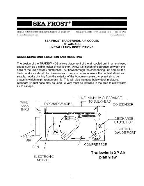
An un-ducted unit in a poorly ventilated small space will heat the air, thereby loweringthe capacity of the unit and possibly causing damage by over-heating the compressor.Service access and installation requires that the front, top, and left end should beaccessible. The duct hose will require 4 inches of clearance past the end of the unit.Mount the TRADEWINDS level. (The compressor is at the bottom). The unit may beplatform mounted. Holes have been drilled through the bottom of the housing forfastening to a platform.INSTALLATION REQUIREMENTSThe air inlet should never be blocked.• Provide for driest, coolest air for intake.• Total combined air duct length should not exceed six feet.• For intake through a finished panel, order a black 4” flange grill.EXPANSION VALVEConnect the expansion valve to either of the 3/8" tubes on the plate or in two platesystems one of the tubes on one of the plates.The valve should be located to allow access to the screw cap on top of the valve. It ispreferable that the cap be up.Trim the tube ends on the plate as necessary. However, allow at least 3/4" to insert intothe fitting. Refer to the Swagelok installation instructions in the following pages.The expansion valve can be mounted inside the box or outside. If it is mounted outsideit will need to be insulated with cork tape and foam to prevent unwanted sweating anddripping.JUMPERTwo plate systems will need a 3/8” jumper line between the plates.THE RECEIVER FILTER DRIER (RFD)Note: Unpack and fit the RFD last and at the time of evacuation and charging toprevent saturating the desiccant with moisture.2
Mount the RFD external to the TRADEWINDS cabinet, connecting to the 1/4" liquid line.It must be mounted vertically with the fittings at the top. It is fitted with a sight glass forchecking the charge. This glass is best viewed looking straight into the top. Install theRFD in a location that allows proper viewing of the sight glass. The RFD must beinstalled in the proper flow direction. Connect the tube from the compressor to the inside of the RFD. The out connects to the tube that connects to the valve.RUNNING TUBING LINESTwo copper lines connect the plate (or plates) and the compressor. One is 3/8" and theother is 1/4".Run the 1/4" liquid line between the condensing unit area and the expansion valve. This1/4" line makes up at the expansion valve. The externally mounted receiver filter drierwill be fitted to this line. The 3/8" line connects to the un-connected plate tube end (orsecond plate) with a 3/8" fitting. The other end of this 3/8" line connects at thecompressor.Run the 1/4" liquid line in contact with 3/8" suction line for at least three feet from thecabinet. Wrap these two tubes tightly together with electrical tape. Insulate this section.This will improve operation and prevent moisture from condensing on the coldestsection of these tubes. It is recommended but not required to insulate the remaininglength of 3/8" return line to the compressor.CAP TUBE ENDSBe sure to keep the copper tubing clean and free of moisture by capping the tubing aftereach cut with the plastic caps provided.Support the tubing every 18 inches as necessary using tie wraps fastened with selftapingscrews.WARNING: The TRADEWINDS unit is shipped with some nitrogen pressure.Before removing the caps on the connection ports, remove the screw caps on theservice valve covers and depress the valves cores to vent any existing pressure.COMPRESSOR CONNECTIONSWorking one line at a time, remove the Swagelok caps from compressor and condenserfittings. Attach the union fitting bodies. This is a pre-swaged connection; See theSwagelok fittings text in this manual. Make up of these pre-swaged connections is 1/4turn from wrench snug. Connect the 1/4" line to the condenser fitting and 3/8" line tothe compressor. Tighten these fittings 1-1/4 turns from wrench snug.3
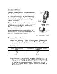
NOTES ON SWAGELOK FITTINGSSwagelok fittings come to you completely assembled, finger-tight. (Pieces a, b, and c inDrawing #1 are already together). They are ready for immediate use.Disassembly <strong>before</strong> use can result in dirt and foreign material getting into the fitting andcausing leaks and you risk damaging the threads if nuts are removed. If disassembly isnecessary, reassemble per drawing.This is a double ferrule system. The most serious installation problem encountered withSEA FROST is the improper assembly of these fittings. Be sure that you assemble allfittings as in Drawing #1.To ease assembly slacken the fitting nut slightly <strong>before</strong> assembly. Then retighten withfingers <strong>before</strong> tightening with a wrench. (This is to avoid cross threading.)Step 1. Always leave two inches of straight, undistorted tubing leading to all Swagelokfittings to allow proper connection.Step 2. Prior to inserting 1/2" tubing into the Swagelok tube fitting, make a pencil mark1" from end of tube. Prior to inserting 3/8" tubing, make a pencil mark 3/4" from the endof the tube. With 1/4" tubing make a mark 5/8" from the end.Step 3. Insert clean, smooth tubing with the pencil mark into the Swagelok tube fitting.You can be sure the tube is resting firmly on the shoulder of the fitting when the pencilmark is flush with the nut. This mark will also indicate that the tube has not moved<strong>before</strong> tightening. (As the fitting is tightened the space from the pencil mark to theshoulder will increase.)Step 4. Tighten the Swagelok nut to a wrench snug* position. Scribe the nut with apencil at the 6:00 o'clock position (see drawing #1, step # 2).* Wrench snug is the first point in the assembly tightening when the tube cannot bepulled from the fitting, (i.e. when the ferrules tighten enough to contact the tubing).Step 5. Now, while holding the fitting body with a back-up wrench, tighten the nut oneand-one-quarterturns ( 1-1/4). To do so, watch the scribe mark, make one completerevolution, and continue to the 9:00 o'clock position. (See drawing #1, step #3).4
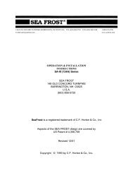
DRAWING 1STEP 1Simply insert the tubing into theSWAGELOK tube fitting. Make sure thatthe tubing rest firmly on the shoulder ofthe fitting and that the nut is wrenchsnug.STEP 2Before tightening the SWAGELOK nut,scribe the nut at the six o'clock position.STEP 3Now, while holding the fitting body steadywith a backup wrench, tighten the nut 1 1/4turns. Watch the scribe mark, make onecomplete revolution and continue to the 9o'clock position. By scribing the nut at the 6o'clock position as it appears to you, therewill be no doubt as to the starting position.When tightened 1 1/4 turns to the 9 o'clockposition you can easily see that the fittinghas been properly installed.5
SWAGELOK FITTINGS ARE TO BE TIGHTENED TO A TORQUE SPEC, NOT INFINITETIGHTNESS. BE SURE YOUR STARTING POINT IS WRENCH SNUG. A DISTORTEDTUBE MIGHT GIVE A FALSE STARTING POINT.* When making all connections, USE TWO WRENCHES. Don't allow the fittings to turnor twist when tightening.RECONNECTING PRE-SWAGED FITTINGSConnections can be disconnected and retightened many times.When reconnecting, insert the tubing with pre-swaged ferrules into the fitting until thefront ferrule seats in the fitting. Tighten the nut by hand. After tightening to wrenchsnug, rotate the nut about one-quarter turn with a wrench.SWAGELOK PERFORMANCESwagelok fittings have built-in spring interaction between the ferrules. Thiscompensates for temperature changes and allows the fittings to be reconnected manytimes. As the fitting is tightened, a burnishing occurs between the body of the fitting andthe ferrules and between the ferrules and the tube. This action provides the tightestconnection available.6
REMOTE THERMOSTAT INSTALLATION & WIRINGFor the best looking job, the thermostat should be recessed into a panel. A cuttingtemplate is provided. Locate the thermostat close enough for the bulb on the sensingtube (pig tail type coil) to reach a mounting ear on the plate. On two plate systems thebulb must be attached to the second plate. This is the plate without the valve. It isnecessary that the bulb end of the sensing tube be in excellent thermal contact with theplate. Neatly coil any extra sensing tube in the box and secure with ties.The sensing tube is hollow; avoid bending it into kinks.Aluminum Holdover Plates:Attach the thermostat bulb to the plate using the stainless steel clip. Use one of theexisting plate mounting screws as an attachment point. Neatly coil any extra sensingtube in the box and secure with ties.Aluminum Block:Attach the bulb to the center of the bottom of the block using a 1/4"- 20 x 1/2" pan headinto the pre-tapped hole.Stainless Steel Evaporator plates:Slide the bulb clip onto the edge of the plate and over thesensing bulb as shown in the drawing to the right. Thesensing bulb must be in excellent thermal contact with theplate. We recommend that the probe be mounted on theplate in the one of the lower mounting positions as shown inthe drawing below. This is best because these positionsremain colder7
The SEA FROST BD thermostat is variable. Turningthe knob fully counterclockwise turns the unit "OFF".The full clockwise setting is the coldest. Thethermostat may be adjusted to obtain anytemperature desired in the cabinet. The thermostatmay be calibrated should the warmest setting be toocold. To calibrate the thermostat remove themounting screws and tip the panel forward. Removethe electrical tape (if necessary) the adjustmentscrew about an inch into the case.To lower box temperature, rotate this screw counterclockwise. One full revolution will change the boxtemperature approximately 6 degrees F. To raise thetemperature in the box rotate the screw clockwise.Make small adjustments. Record all adjustments.STANDARD THERMOSTAT WIRINGConnect the thermostat wires at the compressor module to terminals T & C usingfemale 1/4" female crimp connectors. This is for AEO operation. There is no polarityrequirement.Remote (snowflake panel) thermostat wires ~ red.Electronic thermostat thermometer (version 1) wires ~ green and whiteElectronic thermostat thermometer (version 2 & 3) cat 5 data cable with RJ 45connector. Install a 3-amp ATC fuse in the fuse holder on the Module PCB board. ThePBC board fuse is required only if using Electronic Thermostat with the RJ-45jack.ELECTRONIC THERMOSTAT THERMOMETER (Option)Follow the detailed instructions provided with the ETT.CONNECTIONSFor best performance, the electronic module should be connected directly to the batteryor battery selector switch. Connecting the module through the boat's breaker panel maycause a voltage drop; small wires and multiple connectors create resistance. If usingthe ships panel check the integrity of all the connections and wire size including theground buss feed.8
WIRE SIZE12-volt installations use AWG #8 wire for distances up to 10-feet for the wire pair, and#6 AWG wire for distances up to 25 feet for the wire pair. Fuse 30 Amps.24 Volts: The unit is the same, the module will self calibrate to the applied voltage andprovide proper fan voltage. Fuse 15 Amps.Calculate wire size based on the fuse size and a 3% voltage drop. Follow ABYC wiringguidelines for proper, safe wiring. In any application, use the next largest wire if in doubtto prevent a voltage drop. A fuse is preferred over a breaker as it has less potentialvoltage drop.Connect a red wire from 12 or 24 volts positive to the (+) terminal of the module.Connect a black or yellow wire from 12 or 24 volts negative to the (-) terminal of themodule.Do not operate the BD directly from a DC charger without a battery.WIRING DIAGRAM1. Electronic unit2. Battery3. Main switch(optional)4. LED for operationalerrors5. Fan6. Thermostat7. Resister for presettingspeed(optional)8. Resister for presettingBatteryprotection voltage(optional)9. Fuse (see electricalconnectionsCOMMISSIONINGAttach clean, purged R-134a gauges. The blue hose connects to the suction serviceport on compressor. This is the blue-capped tube stub on the compressor. The redhose connects to the red-capped port on the discharge line.9
CHECK FOR LEAKSRefer to the refrigerant handling section of this instruction manual then return to thispage.CHARGE: This system operates with refrigerant R-134a. The proper chargeamount is 6-12 oz.WARNING! Do not use refrigerant with any additives, including but not limited to:oil, dye, and leak stop.This may be liquid-fed into the low side after evacuation, <strong>before</strong> the compressor isoperated. An automatic expansion valve regulates the evaporator pressure. This valveis adjusted to maintain a constant evaporator pressure. The proper charge must beadded <strong>before</strong> the valve can be accurately set.ADJUSTING THE VALVEBefore operating the compressor, unscrew the plastic cover on the valve body. Notethe adjusting knob. Counter-clockwise rotation decreases the pressure. Clockwiserotation increases the pressure. One turn should equal a 2-psi pressure change.Check that the valve is set in the "0" position. The "0" position is when the top thread onthe valve adjustment knob is even with the valve body. See drawing below.Start the compressor. The valve must beadjusted to a 0 to 2 psi reading on the low sidegauge port. Be sure your gauge is set at O<strong>before</strong> hook-up. Allow several minutes betweeneach adjustment. Moisture may form on theadjusting knob side of the valve and freezecausing the valve to malfunction. To preventthis, replace the cap after each adjustment. Besure the valve is dry <strong>before</strong> final capreplacement. Operate for 30 minutes to confirmproper valve setting and operation.The valve may need to be cleared of dirt or chipsif adjustment is not possible. With the compressor running, turn the valve adjustmentknob clockwise about 3 turns momentarily, and then back to the proper setting. Do notleave the valve in open position (allowing high backpressure) as this may cause thecompressor to overload.After satisfactory adjustment, turn off the thermostat. Remove the gauges. Recap theservice ports. Replace the service panel. When the valve has dried, insulate the valvebody (if it is outside the box) by wrapping it with foam and cork tape. This is to prevent10
condensation. Also insulate the one-foot section of 3/8" tubing that exits the cabinet.The valve need not be insulated if the valve is in the icebox.Trouble shooting note: The operating pressure of the system will not indicate theamount of refrigerant in the system. The valve will not give proper operation orpressure if it is undercharged. Check the valve scribe line. It should correlate to gaugepressure.The system requires enough refrigerant to supply liquid to the valve. If the valve has asteady hissing sound then the charge is okay. If the valve is sputtering then it is low. Ifthe valve is making a noticeable roar it is empty. If the low side pressure is properly setthe high side pressure will be 80 to 135 psi. depending on the air temperature (50 to 95degrees F.) through the unit. Almost immediately upon start up the valve body willbegin to frost.OPERATION DESCRIPTIONThe SEA FROST TRADEWINDS is a small system. It is efficient in its electricalconversion of energy to heat movement. It’s rate of cooling is 1/20 th the rate of theEngine Drive system. By being small it is quiet, compact, has low electrical startingrequirements and running power draw. The TRADEWINDS will operate in up to 120degrees of ambient air temperature. Because of its size it may operate 70 percent of thetime if cooling larger boxes in warm climates. The unit will freeze the holdover platefrom warm but may take all day. If rapid cooling of the system is needed operate theEngine Drive to bring the system to its cooling temperature then let the TRADEWINDStake over. The unit will automatically operate if the thermostat is on and 12 VOLTSD.C. is available. The system may be operated using the shore power charger tomaintain the batteries. The TRADEWINDS and the Engine Drive are separate units andmay be operated simultaneously. Both units are controlled by separate controls.DEFROSTINGExcessive frost/ice build up on the plate or block will reduce the cooling effect.Allowing the unit to warm above freezing is one method of defrosting. Warm water or ahair dryer is also a quick method. The SEA FROST plates can be scraped with aspatula or ice scraper to remove excessive frost build up.OPERATION INSPECTIONWithin a few minutes of starting the TRADEWINDS, tubing in close proximity to thevalve and the valve itself will be noticeably cold. If after 20 minutes of operationcooling in this area is not observed do not continue to operate the system.11
OPERATIONAL INFORMATIONVOLTAGE:AMP DRAW:WIRE SIZE TO BATTERY SUPPLY:FOR 12 VOLT OPERATIONLOW VOLTAGE CUT-OFFFUSE MAXINSTALLED AT BATTERY12 D.C. or 24 D.C.3.3-14 @ 12 VOLTS2 to 3 @ 24 VOLTSAWG # 8 TO 10 FEETAWG # 6 MAXIMUM 25 FEET10.4 VOLTS / 12 VOLTS22.8 VOLTS / 24 VOLTS12-VOLT -30 AMP STANDARD AUTOMOTIVE24-VOLT - 15 AMP STANDARDAUTOMOTIVESERVICE NOTE: The TRADEWINDS is intended to operate with the cover in place.When operating with a manifold gauge set, be sure to block off the top and front withcardboard and tape to maintain proper airflow to the condenser.12
TROUBLESHOOTINGA light emitting diode (LED) is connected between terminals + and D. In case theelectronic unit records an operational error, the diode will flash a number of times. Thenumber of flashes depends on what kind of operational error was recorded. Each flashlasts 1/4 second. After the actual number of flashes there will be a delay with noflashes, the sequence for each error recording is repeated every 4 seconds. Flasheswill only occur in the fault mode with the system on.See additional trouble shooting information available at www.seafrost.comOPERATIONAL ERRORS SHOWN BY LEDNumber ofError typeflashes5 Thermal cut-out of electronic unit (If the refrigeration systemhas been too heavily loaded, or if the ambient temperature is high,the electronic unit will run too hot.)4 Minimum motor speed error (If the refrigeration system is tooheavily loaded, the motor cannot maintain minimum speed 1,850rpm.)3 Motor start errorA. (The system might be overcharged.) Has charge been added?B. Faulty module.C. This fault may also occur when the compressor is trying to starta warm system or on initial start up on a new system. Severalattempts and then start up can be normal.Do not let out refrigerant until first contacting <strong>Sea</strong>frost!2 Fan over-current cut-out (The fan is defective.)1 Battery protection cut-out (The voltage is outside the cut-outsetting. Low voltage.)13
148 OLD CONCORD TURNPIKE BARRINGTON, NH 03825 USA TEL (603) 868-5720 FAX (603) 868-1040 1-800-435-6708E-Mail:sales@seafrost.comwww.seafrost.comTHERMOSTAT CALIBRATION INSTRUCTIONSNote: Be sure that the unit is operating properly <strong>before</strong> making any thermostatadjustments. The sensing bulb must be in excellent thermal contact with the plate orblock.The range of this control may be changed. To access the adjustment screw, removethe four mounting screws on the thermostat panel. Tip the panel forward and make theadjustment with a torx or small phillips head screwdriver.Make small adjustments. Record alladjustments.If the lowest setting on the thermostat panel istoo cold:• Turn the adjustment screw clockwise.One 360-degree turn will raise the boxtemperature approximately 6 degrees f.If the highest setting on the thermostat panel istoo warm:• Turn the adjustment screwcounterclockwise.17
HOLDOVER PLATESSTAINLESS STEELEVAPORATOR PLATES18