CG5-S - SMC
CG5-S - SMC
CG5-S - SMC
- No tags were found...

You also want an ePaper? Increase the reach of your titles
YUMPU automatically turns print PDFs into web optimized ePapers that Google loves.
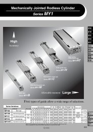
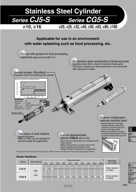
Stainless Steel CylinderSeries CJ5-Sø10, ø16Series <strong>CG5</strong>-Sø20, ø25, ø32, ø40, ø50, ø63, ø80, ø100Applicable for use in an environmentwith water splashing such as food processing, etc.For use with grease for food processingmachines (Approved by NSF-H1)Special scraper (Standard)Prevents water from entering the cylinder.All stainless steel specifications (External parts)Stainless steel 304 is used for external metal parts.Corrosion resistance is improved even in environmentswith exposure to water.Relation of Liquid Entry and Sliding DistanceAmount of liquid entry (g)15105xStandard cylinderStainless steel cylinder0 50 100 150 200 250 300Sliding distance (km)ConditionsWorking fluid ······· AirPressure ············· 0.5 MPaLiquid ·················· Water-soluble coolantPiston speed ······· 200 mm/sOperating frequency··· 60 cpmSpecial scraperTwo types of seal material(Nitrile rubber) (Fluororubber)NBR or FKM can be selected toaccommodate the application.Can be disassembled(Series <strong>CG5</strong>-S ø20 to 40)Since seals are replaceable, this extends the lifeof the cylinder.(Before disassembly, be sure to refer to thesection regarding maintenance under“Specific Product Precautions” on page 850.)This product cannot be used in the food zone. Refer to the Product Specific Precautions (page 849) for details.Exterior configurationreduces residual liquid• Electropolishing of mountingbracket surfaces makes themsmoother to prevent build-up ofliquids and foreign matter.• Plugs are provided for unusedmounting threads (Series <strong>CG5</strong>-S)to prevent residue build-up in thethreads.PlugCJ5<strong>CG5</strong>HYCMSeries VariationsSeriesCJ5-S<strong>CG5</strong>-SSeal materialNBR•FKMBore size (mm)10 16 20 25 32 40 50 63 80 100Applicableauto switchWater resistantD-H7BALWater resistantD-G5BAL833D--XIndividual-XTechnicaldata
Stainless Steel CylinderSeries CJ5-Sø10, ø16How to Order1016Bore size10 mm16 mmBLFDWith auto switchMounting styleBasic styleAxial foot styleRod side flange styleDouble clevis styleCJ5 L 16 S R 60Cylinder stroke (mm)Refer to “Standard Stroke” on page 835.CDJ5 L 16 S R 60 H7BALWith auto switch(Built-in magnet)Stainless steel cylinderMade to OrderRefer to page 835for details.Built-in Magnet Cylinder ModelIf a built-in magnet cylinder without an autoswitch is required, there is no need to enterthe symbol for the auto switch.(Example) CDJ5B10SV-45RRVSeal materialNBR seals (Nitrile rubber)FKM seals (Fluororubber)Port location on head coverNil Perpendicular to axisR In-line∗ Only perpendicular to the axisfor double clevis style.Auto switchBH7BALNumber ofauto switchesNil 2 pcs.S 1 pc.n “n” pcs.Without auto switchD-H7BAL (Water resistant)Only band mounting auto switches areavailable.Applicable Auto Switch/Refer to page 1306 for further information on auto switches.TypeSolid state switchSpecial functionWater resistant(2-color indication)ElectricalentryGrommetIndicatorlightYesWiring(Output)Load voltageDC24 V 12 VAuto switchmodelH7BALead wire length (m)∗3 5(L) (Z)∗ Lead wire length symbols: 3 m··········L (Example) H7BAL∗ Solid state auto switches marked with “5 m··········Z (Example) H7BAZ• For details about auto switches with pre-wired connector, refer to pages 1328 and 1329.2-wirePre-wiredconnectorApplicableloadRelay,PLC” are produced upon receipt of order.Auto Switch Mounting Bracket Part No.16Mounting bracketBore size (mm)10T-bracket ∗ CJ-T010 Stainless steel CJ-T016 Stainless steelFootFlangeCJ-L016 Stainless steelCJ-F016 Stainless steelCJK-L016 Stainless steelCJK-F016 Stainless steel∗ T-bracket is applicable to the double clevis style (D).DescriptionFoot x 1Flange x 1T-bracket x 1Grease pack for stainless steel cylinders/Part no.: GR-R-010 (10 g)834
Series CJ5-SConstruction (Not able to disassemble.)Component PartsNo.12345678DescriptionRod coverHead coverCylinder tubePiston rodMounting nutRod end nutLabel protectorWater resistant scraperMaterialStainless steel 304Stainless steel 304Stainless steel 304Stainless steel 304Stainless steel 304Stainless steel 304PETCJ5SRNBRCJ5SVFKMNote 1) Component part material and surface treatment other than listed aboveare the same as the standard type of Series CJ2.Note 2) The material for seals and bumpers of CJ5SV is FKM.836
¿D¿D¿NDh8Stainless Steel Cylinder Series CJ5-SDimensionsBasic style (B): CJ5BS R V¿CAMMNNGAGBPiping port 2xM5x0.8 Piping port M5 x 0.8¿CBBABB0Ð0.30Ð0.3BA0Ð0.3AHF NA NBS + StrokeBB0Ð0.3With head cover port inaxial location (R)Z + Stroke(mm)Bore size (mm)ABABBCACBDFGAGBHMMNNNANBNDh8SZ101615151518.31218.317201420458888552828M4 x 0.7M5 x 0.8M10 x 1.0M12 x 1.012.512.59.59.5010 Ð0.022012 Ð0.02746477475Axial foot style (L): CJ5LS R V0Ð0.3BA¿CACover surfaceMMNNF GAPiping port 2xM5x0.8GBBA0Ð0.3¿CBRod cover sidePiping port M5 x 0.8LXLZLHLBLYLTA XYHNAZ + StrokeS + StrokeNBBB 0Ð0.3BB0Ð0.3With head cover port inaxial location (R)2x¿LCMounting holeCJ5<strong>CG5</strong>(mm)HYBore size (mm)1016A1515BA BB15 1218.3 18.3CA1720CB1420D45F88GA88GB55H2828LB21.523LC5.55.5LH1414LT2.52.5LX3333LY2525LZ4242MMM4 x 0.7M5 x 0.8NNM10 x 1.0M12 x 1.0NA12.512.5NB9.59.5S4647X66Y99Z7475CMD--XIndividual-XTechnicaldata837
øDøDSeries CJ5-SDimensionsRod side flange style (F): CJ5FS R V0–0.3BAøCARod cover sideCover surfaceMMNNGAPiping port 2 x M5 x 0.8GBøCBBA0–0.3Piping port M5 x 0.82 x øFCMountingholeFXFZFBFYAHFFTNAS + StrokeZ + StrokeNB0–0.3BBBBWith head cover port inaxial location (R)0–0.3(mm)Bore size (mm)ABABBCACBDFFBFCFTFXFYFZGAGBHMMNNNANBSZ101615151518.31218.317201420458817.5195.55.52.52.533332020424288552828M4 x 0.7M5 x 0.8M10 x 1.0M12 x 1.012.512.59.59.546477475Double clevis style (D): CJ5DS R VGAPiping port 2 x M5 x 0.8NBGB+ 0.030øCDH9 0–0.030Clevis pin ( øCdd9 –0.060)øCAMMøCBBA0–0.3BB0–0.3BA0–0.3AHNAZ + StrokeZZ + StrokeS + StrokeURCXBB+ 0.2+ 0.10–0.3(mm)Bore size (mm)ABABBCACBCD(Cd)CXDGAGBHMMNANBRSUZZZ101615151518.31218.3172014203.353.26.5458818232828M4 x 0.7M5 x 0.812.512.522.527.558464781082858793∗ Clevis pin and retaining ring are shipped together.838
Stainless Steel Cylinder Series CJ5-SAccessory DimensionsSingle Knuckle JointClevis PinKnuckle PinMM+ 0.2A1 U1 0L1 7R1øND hole H101212–0.1NX –0.3tmLltmødøDd9tmLltmødøDd9Material: Stainless steel 304 Material: Pin and retaining ring both stainless steel 304ApplicableApplicableApplicablePart no. bore size A1 L1 MM NDH10 NX R1 U1 Part no. bore size Dd9 d L l m t retaining(mm)(mm)ring+ 0.048–0.030I-J010SUS 10 8 21 M4 x 0.7 3.3 0 3.1 8 9 CD-J010 10 3.3 –0.060 3 15.2 12.2 1.2 0.3 Type C 3.2+ 0.048–0.030I-J016SUS 16 8 25 M5 x 0.8 5 0 6.4 12 14 CD-Z015SUS 16 5 –0.060 4.8 22.7 18.3 1.5 0.7 Type C 5Material: Pin and retaining ring both stainless steel 304ApplicableApplicablePart no. bore size(mm)Dd9 d L l m t retainingringCD-J010 10–0.0303.3 –0.060 3 15.2 12.2 1.2 0.3 Type C 3.2IY-J015SUS 16–0.0305 –0.060 4.8 16.6 12.2 1.5 0.7 Type C 5∗ Retaining rings are included. ∗ Clevis pin is used instead for ø10.∗ Retaining rings are included.Double Knuckle JointMounting NutRod End NutMMøND hole H10Shaft d9R1Ldd12CCA1+ 0.2U1 0L1 7NX∗ Knuckle pin and retaining ring are packaged together.Material: Stainless steel 304ApplicablePart no. bore size(mm)A1 L L1 MM NDd9Y-J010SUS 10 8 15.2 21 M4 x 0.7–0.0303.3 –0.060Y-J016SUS 16 11 16.6 21 M5 x 0.8 5–0.030–0.06012+ 0.20BApplicablePart no. bore size(mm)SNJ-016SUS 10SNKJ-016SUS 16HMaterial: Stainless steel 304 Material: Stainless steel 304ApplicableB C d HPart no. bore size(mm)B C d H141716.219.6M10 x 1.0M12 x 1.044NTJ-010SUSNTJ-015SUS1016788.19.2M4 x 0.7M5 x 0.83.24BHPart no.NDH10NXR1U1Y-J010SUSY-J016SUS+ 0.048 3.3 0+ 0.0485 03.26.58121010T-bracketDouble clevis style cylinder7 THTU–0.1TN –0.3øTDH10+ 0.2012TK4 x øTCTXTVRod End CapFlat type/CJ-CFA MMC0.5NLC0.5Round type/CJ-CRA MMøDWCJ5<strong>CG5</strong>HYCMApplicablePart no.CJ-T010SUSCJ-T016SUSbore size(mm)1016TC4.55.5TDH103.35+ 0.0480+ 0.0480TH2935TTTK TN18 3.120 6.4TYTWMaterial: Stainless steel 304TT TU TV TW TX TY2 9 40 22 32 122.5 14 48 28 38 16RRNLC0.5øDMaterial: PolyacetalPart no.Applicablebore size A D LFlat type Round type (mm)MM N R WCJ-CF010 CJ-CR010CJ-CF016 CJ-CR01610168 10 1310 12 15M4 x 0.7M5 x 0.86 10 87 12 10W839D--XIndividual-XTechnicaldata
Stainless Steel CylinderSeries <strong>CG5</strong>-Sø20, ø25, ø32, ø40, ø50, ø63, ø80, ø100How to OrderWith auto switchWith auto switch(Built-in magnet)BLFGEMounting styleBasic styleAxial foot styleRod side flange styleHead side flange styleClevis integrated styleNAPort thread typeRubber bumperNilTNTFRcNPTM5 x 0.8GStainless steel cylinderCDG5 L N25 SR100 G5BAL20253240<strong>CG5</strong> L N 2520 mm25 mm32 mm40 mmTypeNon-lube, Rubber bumperNon-lube, Air cushionø20 to ø100ø20, ø25ø32 to ø100506380100Air cushionNilTNTFBore size50 mm63 mm80 mm100 mmM5 x 0.8RcNPTGø20, ø25ø32 to ø100SSeal materialRVR 100Applicable Auto Switch/Refer to page 1307 for further information on auto switches.TypeSolid state switchSpecialfunctionWater resistant(2-color indication)ElectricalentryGrommetIndicatorlightYesWiring(Output)2-wireNBR seals (Nitrile rubber)FKM seals (Fluororubber)Load voltageDC24 V 12 VAuto switchNil Without auto switchG5BAL D-G5BAL (Water resistant)Auto switches are available in the bandmounting style only.Cylinder stroke (mm)Refer to “Standard Stroke” on page 841.Auto switchmodelG5BALead wire length (m)∗3 5(L) (Z)∗ Lead wire length symbols: 3 m··········L (Example) G5BAL∗ Solid state auto switches marked with “5 m··········Z (Example) G5BAZ• For details about auto switches with pre-wired connector, refer to page 1328 and 1329.Made to OrderRefer to page 841for details.Number ofauto switchesNil 2 pcs.S 1 pc.n “n” pcs.Built-in Magnet Cylinder ModelIf a built-in magnet cylinder without an autoswitch is required, there is no need to enterthe symbol for the auto switch.(Example) CDG5BA40SV-100Pre-wiredconnectorApplicableloadRelay,PLC” are produced upon receipt of order.Mounting Bracket Part No.MountingbracketFootFlangePivot bracketMin.order2 Note)1120 25CG-L020SUSCG-F020SUSCG-L025SUSCG-F025SUSCG-E020SUSBore size (mm)32 40 50 63CG-L032SUSCG-F032SUSCG-E032SUSNote) When ordering the foot bracket, order 2 pcs. per cylinder.Grease pack for stainless steel cylinders/Part no.: GR-R-010 (10 g)CG-L040SUSCG-F040SUSCG-L050SUSCG-F050SUSCG-L063SUSCG-F063SUSCG-E050SUS80 100CG-L080SUSCG-F080SUSCG-E080SUSCG-L100SUSCG-F100SUSDescriptionFoot x 2Bracket mounting bolt x 4Flange x 1Bracket mounting bolt x 4Clevis pin x 1Retaining ring x 2840
Stainless Steel Cylinder Series <strong>CG5</strong>-SSpecificationsJIS SymbolDouble acting,Single rodBore size (mm)ActionFluidProof pressureMaximum operating pressureMinimum operating pressureAmbient and fluid temperatureCushionLubricationPiston speedStroke length toleranceMounting styleStandard Stroke20 25 32 40 50 63 80 100Double acting, Single rodAir1.5 MPa1.0 MPa0.05 MPaWithout auto switch: –10 to 70°C With auto switch: –10 to 60°CRubber bumper, Air cushionNot required (Non-lube)50 to 1000 mm/s 50 to 700 mm/sst + 1.4Up to 1000 mm,st + 1.4st + 1.50Up to 1000 0 mm, Up to 1200 0 mmst + 1.5Up to 1500 0 mmBasic style, Axial foot style, Rod side flange style,Head side flange style, Clevis integrated styleSymbol-XA-XB6Made to Order Specifications(For details, refer to pages 1380 and 1397.)SpecificationsChange of rod end shapeHeat resistant cylinder (150°C) ∗∗ Heat resistant grease (non-food grease) is used.Bore size (mm)2025324050, 6380100AccessoryMassStandard stroke25, 50, 75, 100, 125, 150, 20025, 50, 75, 100, 125, 150, 200250, 300MountingLong stroke201 to 350301 to 400301 to 450301 to 800301 to 1200301 to 1400301 to 1500Maximum manufacturable stroke∗ Manufacture of intermediate strokes at 1 mm intervals is possible. (Spacers are not used.)∗ Long stroke applies to the axial foot style and the rod side flange style. If other mounting brackets areused, or the length exceeds the long stroke limit, the stroke should be determined based on the strokeselection table (front matter 28, CG1).StandardequipmentOptionRod end nutSingle knuckle jointDouble knuckle joint (With pin & retaining ring)Pivot bracket (With pin and retaining ring)BasicstyleAxialfoot styleRod sideflange style(kg)Bore size (mm)Basic styleAxial foot styleFlange styleClevis integrated stylePivot bracketSingle knuckle jointDouble knuckle joint (with pin)Additional mass per each 50 mm of strokeAdditional mass with air cushion200.320.400.430.370.080.040.050.060.02250.420.530.530.480.080.070.090.080.02320.610.720.710.720.180.070.090.140.03400.971.131.121.120.180.110.180.180.02501.782.122.042.170.460.220.330.270.06632.733.193.253.260.460.220.330.330.07805.205.915.866.481.650.530.730.500.141008.139.509.299.941.650.781.070.730.16Calculation: (Example) <strong>CG5</strong>LA 20SR-100 • Basic mass································ 0.40 kg (Foot style ø20)(Foot style ø20, 100 stroke) • Additional stroke mass ············· 0.06 kg/50 ST• Air cylinder stroke······················ 100 ST• Additional air cushion mass ····· 0.02 kg0.40 + 0.06 x 100/50 + 0.02 = 0.54 kg841Basic mass1500Head sideflange styleClevisintegratedstyleCJ5<strong>CG5</strong>HYCMD--XIndividual-XTechnicaldata
Series <strong>CG5</strong>-SConstructionWith rubber bumperø80, ø100 ø80, ø100With air cushionComponent PartsNo.1234567141516DescriptionRod coverHead coverCylinder tubePiston rodBumperRod end nutCushion sealCushion valveValve retainerLock nutStainless steel 304MaterialStainless steel 304Stainless steel 304Stainless steel 304UrethaneStainless steel 304UrethaneStainless steel 304Stainless steel 304Stainless steel 304Hard chrome platedNo.8910111213DescriptionWater resistant scraperRod sealPiston sealValve sealValve retainer gasketLabel protectorMaterial<strong>CG5</strong>SR <strong>CG5</strong>SVNBRFKMPETNote 1) Component part material and surface treatment other than listed aboveare the same as the standard type of Series CG1.Note 2) For cylinders with an auto switch, the piston is fixed with a magnet.Replacement Parts/Seal KitBore size (mm)20253240Contents<strong>CG5</strong>NSR<strong>CG5</strong>N20SR-PS<strong>CG5</strong>N25SR-PS<strong>CG5</strong>N32SR-PS<strong>CG5</strong>N40SR-PSRubber bumperSet of o and !0 above<strong>CG5</strong>NSV<strong>CG5</strong>N20SV-PS<strong>CG5</strong>N25SV-PS<strong>CG5</strong>N32SV-PS<strong>CG5</strong>N40SV-PSAir cushion<strong>CG5</strong>ASR<strong>CG5</strong>ASV<strong>CG5</strong>A20SR-PS<strong>CG5</strong>A20SV-PS<strong>CG5</strong>A25SR-PS<strong>CG5</strong>A25SV-PS<strong>CG5</strong>A32SR-PS<strong>CG5</strong>A32SV-PS<strong>CG5</strong>A40SR-PS<strong>CG5</strong>A40SV-PSSet of o, !0, !1 and !2 above∗ Seal kit includes a grease pack (10 g).Order with the following part number when only the grease pack is needed.Grease pack part number: GR-R-010 (10 g)CautionWhen disassembling cylinders with bore sizes of ø20 through ø40, grip the double flat part of either the tube cover or the rod cover with a viseand loosen the other side with a wrench or a monkey wrench, etc., and then remove the cover. When retightening, tighten approximately 2degrees more than the original position. (Cylinders with ø50 or larger bore sizes are tightened with a large tightening torque and cannot bedisassembled.)842
Stainless Steel Cylinder Series <strong>CG5</strong>-SDimensionsRBasic style (B): <strong>CG5</strong>BNS V: With rubber bumperWidth across flats B1H1GA2xP(Rc, NPT, G)GBMBMC ±0.1(¿E1)¿D¿IKA±0.1CNA8xJMMALAHK(F1)S + StrokeZZ + StrokeB2BZPlug bolt *(4 pcs. included)Bore StrokeRc, NPT port G portsize rangeA AL B1 B2 BM BZ C D E1 F1 H H1 I J K KA M MM NA S ZZ(mm) Standard GA GB P GA GB P20253240506380100Up to 350Up to 400Up to 450Up to 800Up to 1200Up to 1200Up to 1400Up to 1500181818192121282912121213141420201/81/81/81/81/41/43/81/218181616191925261212101012121717M5 x 0.8M5 x 0.81/81/81/41/43/81/2182222303535404015.519.519.5273232373713171719272732417881013171719M4 x 0.7M5 x 0.8M5 x 0.8M6 x 1.0M8 x 1.25M10 x 1.5M10 x 1.5M12 x 1.7599.59.51215.519192416.518.5202632385060810121620202530151719232828333833333333354040505858717156681111131631333847587289110M4 x 0.7depth 7M5 x 0.8 depth 8M5 x 0.8 depth 8M6 x 1.0 depth 12M8 x 1.25 depth 16M10 x 1.5 depth 16M10 x 1.5 depth 22M12 x 1.75 depth 2355.55.567710106810141818222633.53.545.5778M8 x 1.25M10 x 1.25M10 x 1.25M14 x 1.5M18 x 1.5M18 x 1.5M22 x 1.5M26 x 1.5292935.54455698010083838593109109130131118123125143167167201202* Install plug bolts, which are included, in any unused mounting holes.(mm)RBasic style (B): <strong>CG5</strong>BAS V: With air cushion10¼Wq¼Width across flats B1H1WAGA2xP(Rc, NPT, G)WBGBMBM±0.1CKA±0.1CNAMax.WH8xJ(¿E1)¿DMMALAHK(F1)S + StrokeZZ + Stroke¿IB2BZPlug bolt *(4 pcs. included)Bore StrokeRc, NPT portrangeG portsizeA AL B1 B2 BM BZ C D E1 F1 H H1 I J K KA M MM NA S(mm) Standard GA GB P GA GB P20253240506380Up to 350Up to 400Up to 450Up to 800Up to 1200Up to 1200Up to 14001818181921212812121213141420M5 x 0.8M5 x 0.81/81/81/41/43/81818161619192512121010121217M5 x 0.8M5 x 0.81/81/81/41/43/81822223035354015.519.519.5273232371317171927273278810131717M4 x 0.7M5 x 0.8M5 x 0.8M6 x 1.0M8 x 1.25M10 x 1.5M10 x 1.599.59.51215.5191916.518.52026323850810121620202515171923282833333333335404050585871566811111331333847587289M4 x 0.7depth 7M5 x 0.8 depth 8M5 x 0.8 depth 8M6 x 1.0 depth 12M8 x 1.25 depth 16M10 x 1.5 depth 16M10 x 1.5 depth 2255.55.56771068101418182233.53.545.577M8 x 1.25M10 x 1.25M10 x 1.25M14 x 1.5M18 x 1.5M18 x 1.5M22 x 1.5292935.54455698083838593109109130100 Up to 1500 29 20 1/2 26 17 1/2 40 37 41 19 M12 x 1.75 24 60 30 38 3 71 16 110 M12 x 1.75 depth 23 10 26 8 M26 x 1.5 100 131* Install plug bolts, which are included, in any unused mounting holes.(mm)Boresize(mm)20253240506380100WA WB WH Wq222222222525303116 2316 2516 28.516 3318 40.518 47.522 60.522 71(mm)ZZ30¡ 11830¡ 12325¡ 12520¡ 14320¡ 16720¡ 16720¡ 20120¡ 202843CJ5<strong>CG5</strong>HYCMD--XIndividual-XTechnicaldata
Series <strong>CG5</strong>-SDimensionsNAxial foot style (L): <strong>CG5</strong>L AS R VWidth across flats B1H1HGA2 x P(Rc, NPT, G)S + StrokeGBBLHøDKA8 x JC±0.14 x øLDLXLZMMH1ALAFTKWidth across flats NAX Y Y XLS + StrokeGALT2 x P(Rc, NPT, G)GBMFXCBøDøIC±0.1øIBoresize(mm)20253240506380100StrokerangeStandardUp to 350Up to 400Up to 450Up to 800Up to 1200Up to 1200Up to 1400Up to 1500Rc, NPT portG portGA GB P GA GB P181818192121282912121213141420201/8 (1)1/8 (1)1/81/81/41/43/81/218181616191925261212101012121717M5 x 0.8M5 x 0.81/81/81/41/43/81/2182222303535404015.519.519.52732323737131717192727324137.541.54453.5698199.512516.518.5202632385060∗ Foot brackets and plug bolts are installed when shipped from factory.Note 1) ø20 and ø25 cylinders with an air cushion: M5 x 0.8Note 2) Refer to the basic type (B)/<strong>CG5</strong>BAS ∗ for the dimensions of air cushion needles.NRod side flange style (F): <strong>CG5</strong>F AS R VA AL B1 B C D H H1 I J K KAWidth across flats B1810121620202530354040505858717156681111131631333847587289110ZZ + StrokeM4 x 0.7M5 x 0.8M5 x 0.8M6 x 1.0M8 x 1.25M10 x 1.5M10 x 1.5M12 x 1.7555.55.56771010Boresize(mm)2025324050638010068101418182226LD667.27.210121214LH2225253040455570LS5959596674748283MM NA SM8 x 1.25M10 x 1.25M10 x 1.25M14 x 1.5M18 x 1.5M18 x 1.5M22 x 1.5M26 x 1.5292935.544556980100LT3333444683838593109109130131LX404444546682100120X15151616.521.521.52830LZ5060607590110130160Y7766.511.511.51715(mm)M33.53.545.5778(mm)ZZ124129.5131.5150176.5178212216±0.15±0.1Boresize(mm)20253240506380100StrokerangeStandardUp to 350Up to 400Up to 450Up to 800Up to 1200Up to 1200Up to 1400Up to 15004 x øFDRc, NPT portKACFXB±0.1±0.15G portGA GB P GA GB P181818192121282912121213141420201/8 (1)1/8 (1)1/81/81/41/43/81/218181616191925261212101012121717M5 x 0.8M5 x 0.81/81/81/41/43/81/28 x J182222303535404015.519.519.527323237371317171927273241MM505050607590100125ALA16.518.5202632385060H810121620202530KA AL B1 B C D FX FD FT H H1 I J K KA M MM NA S ZZ36363846587082100∗ Flange bracket and plug bolt are installed when shipped from factory.Note 1) ø20 and ø25 cylinders with an air cushion: M5 x 0.8Note 2) Refer to the basic type (B)/<strong>CG5</strong>BAS ∗ for the dimensions of air cushion needles.8445.55.56.66.69111114Width across flats NA6666999103540405058587171566811111316S + StrokeZZ + Stroke31333847587289110M4 x 0.7M5 x 0.8M5 x 0.8M6 x 1.0M8 x 1.25M10 x 1.5M10 x 1.5M12 x 1.7555.55.567710106810141818222633.53.545.5778M8 x 1.25M10 x 1.25M10 x 1.25M14 x 1.5M18 x 1.5M18 x 1.5M22 x 1.5M26 x 1.5292935.544556980100M83838593109109130131(mm)121126.5128.5147172.5174208210
Stainless Steel Cylinder Series CJ5-S/<strong>CG5</strong>-SProper Auto Switch Mounting Position (Detection at stroke end) and Its Mounting HeightSeries CJ5-SD-H7BAL@ HSMinimum Stroke for Auto Switch MountingMounting bracketNumber of autoswitchesBasic style, Foot style, Flange style, Clevis style10 15 60Auto Switch Mounting Bracket / Part No.1016D-H7BALA00.5B00.5Hs1720.51224.516<strong>SMC</strong><strong>SMC</strong>A29BSwitch mountingsideSwitch typeMinimum stroke (mm)Bore size(mm)10161(Rod cover side)Auto switch mountingbracket part no.BJ2-010SBJ2-016S* With stainless steel mounting screws.2(Different sides)2(Same side)Port side Port side Port sideOperating RangeAuto switch modelD-H7BALBore size (mm)105165(mm)* Since this is a guideline including hysteresis, notmeant to be guaranteed. (Assuming approximately±30% dispersion) There maybe the case to changesubstantiallydepending on an ambientenvironment.Proper Auto Switch Mounting Positionand Its Mounting HeightApplicablebore size (mm)Auto switchmodelNote) Adjust the auto switch after confirming theoperating condition in the actual setting.(mm)Series <strong>CG5</strong>-SD-G5BAL@ HSAuto switchMinimum Stroke for Auto Switch MountingMounting bracketNumber of autoswitchesSwitch mountingsideSwitch typeMinimum stroke (mm)Auto switchmodelD-G5BALNBA-088SNBA-106S1(Rod cover side)BGS1-032SA33Basic style, Foot style, Flange style, Clevis style10 15 75Bore size (mm)20 25 32 40 50 63 80 100BAF-04SBAF-05S2(Different sides)BAF-06SBAF-08SBAF-10SB2(Same side)Port side Port side Port sideAuto Switch Mounting Bracket / Part No.* With stainless steel mounting screws.Operating RangeAuto switchmodelD-G5BAL202532405063801002052555.5677.5(mm)Bore size (mm)32 40 50 63 80 1007.5* Since this is a guideline including hysteresis, notmeant to be guaranteed. (Assuming approximately±30% dispersion) There maybe the case tochange substantiallydepending on an ambientenvironment.Proper Auto Switch Mounting Positionand Its Mounting Height(mm)Applicablebore size (mm)Auto switchmodel8D-G5BALA B Hs31.531.532.53745.545.5565724242528363646462628.53336.54248.557.568Note) Adjust the auto switch after confirming theoperating condition in the actual setting.847CJ5<strong>CG5</strong>HYCMD--XIndividual-XTechnicaldata
Chemical Resistance Table1234567891011121314151617181920212223Technical Data:Chemical Resistance Table: No influence or almost no influence: Some influence, but operational depending on conditions: Avoid use if possible: Substantial influence, not suitable for usePartsMaterialChemical(Concentration weight %, Temperature °C)InorganicsaltInorganicalkaliOrganicsolventOthers(oil, gas,etc.)Hydrochloric acid (20%, Room temperature)Chromic acid (25%, 70°C)Boric acidSulfuric acid (30%, Room temperature)Phosphoric acid (50%, Room temperature)Ammonium hydroxide (28%)Sodium hydroxide (30%, Room temperature)Calcium hydroxideMagnesium hydroxideAcetyleneFormic acid (25%, Room temperature)Citric acidAcetic acid (10%, Room temperature)Lactic acid (5%, 20°C)Linseed oilPolassium chlorideCalcium chlorideMineral oilSodium hypochlorite (2%, Room temperature)Sodium chlorideCarbon dioxideNatural gasBoric acidSymbol: Not testedBody Seal Water resistant auto switchStainless steel Aluminum ∗ Nitrile rubber Fluororubber Resin casingStainlesssteel 304AINBR(–10 to 60°C)FKM(–40 to 150°C)PBT(–10 to 60°C)Lead wirePVC(–10 to 60°C)∗ Unless noted otherwise, the solution concentration is in a saturated state.∗ Chemical resistance is a guide that applies only to the stainless steel cylinder parts, and does not guarantee the performance of air cylinders (auto switches).Be sure to perform a verification test before operating.∗ The temperature range for the protective label cover is between –40 to 110°C, and the temperature range for grease is between –20 to 150°C. (However,there is no relationship with the chemicals listed above.)∗ ) Reference data848
Series CJ5-S/<strong>CG5</strong>-S Stainless Steel CylinderSpecific Product Precautions 1Be sure to read before handling. Refer to front matters 54 and 55 for Safety Instructionsand pages 3 to 11 for Actuator and Auto Switch Precautions.WarningCautionWarningWarningCaution on Design1. Note the mass of the stainless steel products.Since the mass of stainless steel cylinders is approximately 1.5to 3 times heavier than the standard products (with aluminumbody), be careful when calculating mass estimates. Also, whenmounting the cylinder on equipment where vibration is expected,avoid using single side brackets such as the flange style, and usedouble side brackets such as the foot style instead.1. Adjust the speed control for the environment inwhich it will be used.Speed adjustment may be changed depending on theenvironment.2. Dust may accumulate on this product’s mountingscrews and brackets in some operating conditions.Measures must be applied depending on the operatingconditions when mounting.Selection1. Generally, use nitrile rubber (NBR) seals with liquidsthat do not contain chlorine and sulfur, and usefluoro rubber (FKM) seals with liquids that containchlorine and sulfur.However, depending on the type and the brand of liquid (such ascleaning solvent) that splashes on the cylinder, the operating lifeof seals may be reduced dramatically. In cases where specialadditives are used, or where liquid caused trouble with theconventional nitrile or fluoro rubber seals in the past, request aninvestigation or set up a test period for the use of the seals.2. Even the fluoro rubber specification may not beapplicable depending on the type of chemicals andthe operating temperature. Therefore, be sure toverify the seal's applicability before use.Mounting1. Do not rotate the cover.If a cover is rotated when installing a cylinder or screwing afitting into the port, it is likely to damage the junction part withcover.2. When using pins, apply grease, etc., in order toprevent them from degrading of shape and rusting.WarningCautionOperating Environment1. Fully consider the compatibility of stainless steel.The corrosion resistance of stainless steel is not effectiveagainst all media and corrosive environments. Corrosionproceeds rapidly with strong hydrochloric acid, hydrofluoric acid,and high temperature ammonium gas, etc. Therefore itscompatibility to the environment must be considered carefully.2. Do not operate cylinders with auto switches inenvironments where oil and chemicals are used.Please contact <strong>SMC</strong> when operating in environments withcoolants, cleaning solvents, various oils or chemicals, as it maycause adverse effects (faulty insulation, malfunction due toswelling of the potting resin, and hardening of lead wires, etc) toauto switches even in a short period of time. Even with the fluororubber seal specification, the auto switch related parts (switchbody, mounting bracket, and built-in magnet) are identical to thestandard specifications. Therefore, consult with <strong>SMC</strong> regardingthe cylinder’s compatibility (such as chemical resistance) with anenvironment (chemicals, etc.) before operating.3. Do not immerse the cylinder in water or chemicals.When the cylinder is operated in a condition with water pressure,the fluid leaks into the cylinder in the early stages. In the worstcase, the fluid may back flow inside the piping and damage thesolenoid valve.1. Do not use cylinders in a food-related environment.Food zone.....Food may directly contact with cylinder parts,but is not treated as food products.Splash zone.....Food may directly contact with cylinderparts, but is not treated as food products.Non-food zone.....Cylinder parts do not directly contact food.Splash zoneCan be installedFoodFood zoneCannot beinstalledContainerNon-food zoneCan be installedCJ5<strong>CG5</strong>HYCMCautionOperating Precautions1. If cleaning the rotating part, grease may leak out,which shortens product service life. Thus, cleaningmust be as infrequent as possible.2. If excess water gets into mounting holes, unwantedbacteria may reproduce. Plug them with plug bolts orexternal covers to avoid this.2. When cleaning solvent or chemicals splashes on acylinder, the service life may be extremelyshortened. Please contact <strong>SMC</strong> for details.3. When cleaning cylinders with steam, do it as quicklyas possible, keeping the cylinder’s temperaturerange in mind.4. When cleaning cylinders with a brush, etc., do notapply excessive force to the weaker parts, such asauto switch lead wire, etc.849D--XIndividual-XTechnicaldata
Series CJ5-S/<strong>CG5</strong>-S Stainless Steel CylinderSpecific Product Precautions 2Be sure to read before handling. Refer to front matters 54 and 55 for Safety Instructionsand pages 3 to 11 for Actuator and Auto Switch Precautions.WarningMaintenance1. If this cylinder is lubricated, it may cause malfunctions.If grease other than designated is used, it may also causemalfunctions.• Order with the following part number when only the greasefor maintenance is needed.Grease pack part number for stainless steel cylindersGrease for food processing machines: GR-R-010 (10 g)2. Do not wipe grease attached to the rotating part ofthe air cylinder.If grease attached to the rotating part is forcibly wiped off, it maycause malfunctions.If the cylinder is operated for a long period of time, the rotatingpart may become black. In such cases, wipe the greaseattached to the rotating part and reapply fresh grease to enablethe cylinder to operate for a long period of time.(Wipe the grease with water. Using alcohol or solvents maydamage seals.)Precautions for Series <strong>CG5</strong>-S1. Sealant∗ is used on the threads of the connectingsections of the cover and the cylinder tube for airtightconstruction. When disassembling the cylinder,the old sealant must be completely removed, andnew sealant must be applied before re-assembling.∗ Loctite ® 542 (medium strength) or equivalent2. ø50 or larger bore size cylinders cannot be dis-assembled.When disassembling cylinders with bore sizes of ø20 throughø40, grip the double flat part of either the head cover or the rodcover with a vise and loosen the other side with a wrench or amonkey wrench, etc., and then remove the cover. When retightening,tighten approximately 2 degrees more than theoriginal position. (Cylinders with ø50 or larger bore sizes aretightened with a large tightening torque and cannot bedisassembled. Please contact <strong>SMC</strong> when disassembly isrequired.)850