
Create successful ePaper yourself
Turn your PDF publications into a flip-book with our unique Google optimized e-Paper software.
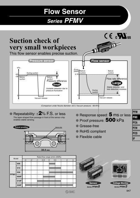
Flow SensorSeries <strong>PFMV</strong>Suction check ofvery small workpiecesThis flow sensor enables precise suction.®Pressure sensorFlow sensorkPa–60–58BeforesuctionDuring suctionBeforesuctionPressure differenceSmallUnstable detection due topressure fluctuationl/min(ANR)0.76BeforesuctionDuringsuctionBeforesuctionFlow rate differenceLargeStable detection andless detection mistakes0Vacuum release0Vacuum release(Comparison under Nozzle diameter: ø0.3, Vacuum pressure: –60 kPa) Repeatability: ±2% F.S. or lessThe taper-shaped flow passage in front of the sensor chipenables stable sensing.Patent pendingSensor chip Response speed: 5 ms or less Proof pressure: 500 kPa Grease-free RoHS compliant Flexible cablePFM<strong>PFMV</strong>PF2APF2WPF2DIF34.4 mmModel505Rated flow range (l/min (ANR))–3 –2 –1 –0.5 0 0.5 1 2 3510<strong>PFMV</strong>530505F510F530FSensorSeries <strong>PFMV</strong>5Voltage MonitorSeries <strong>PFMV</strong>3947
SensorReduced piping spaceMountable in a space-saving location since thestraight piping length is not required.65 mmActual sizeVoltage MonitorA full range of sensors (6 ranges)can be covered by one monitor.No need to select the range of connected sensors(excluding external input). Voltage displayOutput voltage of the sensoris displayed.• Settable range: 0.7 to 5.10 V• Minimum unit setting: 0.01 V∗ When using one-touch fitting, KJL04-M534.4 mm18 mm10 mmMass: 10 gFlexible cableSeries <strong>PFMV</strong>3 ConnectorsEasy connection and removal of wiringPower supply /Output connectorSeries <strong>PFMV</strong>5Measurement flowrange (l/min)0 to 0.50 to 10 to 3–0.5 to 0.5–1 to 1–3 to 3Model<strong>PFMV</strong>505<strong>PFMV</strong>510<strong>PFMV</strong>530<strong>PFMV</strong>505F<strong>PFMV</strong>510F<strong>PFMV</strong>530Fe-con connectorSensor connectorApplications Suction check of very small workpieces• Suction of small components can be checked.• Highly applicable to small nozzles• Detects nozzle clogging and crushing. Easier leakage test• Easily detects pin halls on molded parts. Easier check of the work piece presence• Workpiece presence is easily checked• by flow-rate change.• Sensors can be mounted• as a manifold.• Sensors can be mounted• near pads.948
Mountings Direct mount Manifold mount One-side bracket mount Both-side bracket mount Panel mount Bracket mountSupport for vertical and horizontal secure mounting• A single panel opening is sufficient.• Reduces panel fitting work and enables space-savings.34.5OUT1OUT2OUT1OUT2OUT1OUT2SET SET SETPanel openingPFM<strong>PFMV</strong>PF2APF2WPF2DIF949
Series <strong>PFMV</strong>Model SelectionNozzle Diameter and Flow Characteristics (Approximate values)Use the following graphs as a reference to select sensor measuring range.P2: Nozzle internal pressureNozzle Diameter – Flow Characteristics (Vacuum)5.04.5P1: Atmospheric pressureNozzle Diameter – Flow Characteristics (Positive pressure)5.0ø0.6ø0.54.54.03.5ø0.44.03.5ø0.6ø0.53.02.52.0Flow rate [l/min]ø0.33.02.52.0Flow rate [l/min]ø0.41.5ø0.21.5ø0.31.01.0ø0.20.5ø0.10.0–80 –60 –40 –20 0P2 [kPa]0.00 50 100 150 200 250 300P2 [kPa]ø0.10.5Example (Vacuum)Selecting conditions:Nozzle diameter: ø0.3P1: 0 [kPa]P2: –60 [kPa]The flow rate will be 0.7 to 0.8 [l/min] based on the graph.® Select the <strong>PFMV</strong>510-1.Example (Positive pressure)Selecting conditions:Nozzle diameter: ø0.3P1: 0 [kPa]P2: 20 [kPa]The flow rate will be 0.7 to 0.8 [l/min] based on the graph.® Select the <strong>PFMV</strong>510-1.P1NozzleP2Vacuum source(Vacuum pump)P1NozzleP2Note) Since the calculated value may not meet the approximate value due to leakage and pressure loss in the piping system, please check theresult by using actual equipment.950
Flow SensorSeries <strong>PFMV</strong>5®How to Order<strong>PFMV</strong>5 05 1Measurement flow range05 0.0 to 0.5 l/min10 0.0 to 1.0 l/min30 0.0 to 3.0 l/min05F –0.5 to 0.5 l/min10F –1.0 to 1.0 l/min30F –3.0 to 3.0 l/minOption (shipped together)Nil NoneWith L-type bracketAOutput specification1 Analog output (1 to 5 V)Mountingscrew* 2 L-type brackets (with 2 mounting screws) are included.Instruction manualNil With instruction manual (Leaflet: Japanese and English)N NoneOption/Part No.If a single option or manifold mounting are required, order sensors with the part numbers below separately.Part no.StationsRemarksZS-36-A1ZS-36-A2ZS-36-A3ZS-36-A4ZS-36-A5For 1 station (for single unit)For 2 stationsFor 3 stationsFor 4 stationsFor 5 stations2 L-type brackets, 2 mounting screws M3 x 15L2 L-type brackets, 2 mounting screws M3 x 25L2 L-type brackets, 2 mounting screws M3 x 35L2 L-type brackets, 2 mounting screws M3 x 45L2 L-type brackets, 2 mounting screws M3 x 55LPFM<strong>PFMV</strong>PF2APF2WPF2DIF951
Series <strong>PFMV</strong>5SpecificationsModel<strong>PFMV</strong>505<strong>PFMV</strong>510<strong>PFMV</strong>530<strong>PFMV</strong>505F<strong>PFMV</strong>510F<strong>PFMV</strong>530FApplicable fluidDry air, N2(JIS B 8392-1 1.1.2 to 1.6.2: 2003)Rated flow range (Flow rate range)RepeatabilityPressure characteristics(Based on 0 kPa Note 4) )Temperature characteristics(Based on 25°C)Rated pressure rangeNote 5)Operating pressure rangeNote 6)Proof pressureAnalog output (Non-linear output)Response timePower supply voltageCurrent consumptionEnvironmentalresistanceLead wireMassNote 1)EnclosureFluid temperatureOperating temperature rangeStored temperature rangeOperating humidity rangeStored humidity rangeWithstand voltageInsulation resistanceVibration resistanceImpact resistancePort sizeWetted parts material0 to 0.5l/min0 to 1l/min0 to 3l/min–0.5 to 0.5l/minNote 2)±2 F.S. or lessNote 3)±2% F.S. or less (0 to 300 kPa)±5% F.S. or less (–70 to 0 kPa)±2% F.S. or less (15 to 35°C)±5% F.S. or less (0 to 50°C)–1 to 1l/minNote 2)–70 kPa to 300 kPa–100 kPa to 400 kPa500 kPaVoltage output: 1 to 5 V, Output impedance: Approx. 1 kΩ5 ms or less (90% response)12 to 24 VDC ± 10%, Ripple (p-p) ± 10% or less (with polarity protection)16 mA or lessIP400 to 50°C (with no freezing and condensation)0 to 50°C (with no freezing and condensation)–10 to 60°C (with no freezing and condensation)35 to 85% R.H. (with no condensation)35 to 85% R.H. (with no condensation)1000 VAC for 1 min. between whole charging part and case50 MΩ or more (500 VDC Mega) between whole charging part and case10 to 150 Hz with a 1.5 mm amplitude, max. 98 m/s 2 , in each X, Y, Z direction for 2 hrs (De-energized)980 m/s 2 in X, Y, Z directions 3 times each (De-energized)M5 x 0.8 (Tightening torque: 1 to 1.5 N·m)PPS, Si, Au, Stainless steel 316, C3604 (Electroless nickel plated)Vinyl cabtire cord, 3 cores ø2.6, 0.15 mm 2 , 2 m10 g (excluding lead wire)–3 to 3l/minNote 2)Note 1) Volume flow converted value under standard conditions (ANR) of 20°C, 101.3 kPa and 65% RHNote 2) Analog output indicates 3 V when the flow rate is 0. When the flow direction is from IN to OUT, the output is changed to 5 V, and when it’s from OUT to IN, the output ischanged to 1 V.Note 3) The unit % F.S. is based on the full scale of analog 4 V (1-5 V).Note 4) 0 kPa indicates the atmospheric release.Note 5) Pressure range that satisfies the product specificationsNote 6) Applicable pressure rangeInternal Circuits and Wiring ExamplesMain circuit9521 kΩBrown DC (+)Black OUT (Analog output)LoadBlue DC (–)12 to 24 VDC+–Lead Wire SpecificationsRated temperatureRated voltageNumber of wiresMaterialConductor ConstructionExternal diameterMaterialExternal diameterInsulatorStandard thicknessColorsMaterialSheath Standard thicknessColorFinished external diameter80°C1000 V3Copper alloy wire7/11/0.05 mm0.58 mmCross-linked vinyl chloride (XL-PVC)0.88 mm0.15 mmBrown, Blue, BlackOil-resistant/Heat resistant vinyl0.35 mmLight gray (Munsell N7 equivalent)2.6 +0.1–0.15
Flow Sensor Series <strong>PFMV</strong>5Recommended Pneumatic CircuitsCompressed air lineVacuum lineVacuum lineDryerIDFIDUAir filter Regulator Micro mistseparatorAFARIRAMDAFDFlowsensor<strong>PFMV</strong>SuctionfilterZFSFD100Flowsensor<strong>PFMV</strong>Recommended FittingsOne-touch Fitting/Series KQ2TypeTubing O.D.(mm)Port size ModelMale connectorHex. socket head male connectorMale elbow4 M5 x 0.8KQ2H04-M5KQ2S04-M5KQ2L04-M5One-touch Mini/Series KJTypeTubing O.D.(mm)Port size ModelMale connectorHex. socket head male connectorMale elbow4 M5 x 0.8KJH04-M5KJS04-M5KJL04-M5Miniature Fitting/Series MTubing O.D.Type Port size Model(mm)4M-5AN-4Barb fitting for nylon tubeM5 x 0.86M-5AN-6Internal Constructionq w e r t y e w qComponent PartsNo. Description1 Fitting for piping2 Mesh holding screw3 Mesh4 Body5 Print circuit board6 Sensor chipMaterialC3604 (Electroless nickel plated)Stainless steel 316PPSGE4FSi, AuPFM<strong>PFMV</strong>PF2APF2WPF2DIFDetection PrincipleThis MEMS sensor chip consists of upstream temperature measuring sensor (Ru) and downstreamtemperature measuring sensor (Rd), which are placed symmetrically from the centerof a platinum thin film coated heater (Rh) mounted on a membrane, and an ambient temperaturesensor (Ra) for measuring gas temperature.The principle is as shown in the diagram on the right. (a) When the gas is static, the temperaturedistribution of heated gas centered around Rh is uniform, and Ru and Rd have the sameresistance. (b) When the gas flows from the left side, it upsets the balance of the temperaturedistribution of heated gas, and the resistance of Rd becomes greater than that of Ru.The difference in resistance between Ru and Rd is proportional to the gas velocity, so measurementand analysis of the resistance can show the flow direction and velocity of the gas.Ra is used to compensate the gas and/or ambient temperature.Ru Rh RdRa(a) The gas is static.FlowRu Rh RdRa(b) The gas flows from the left side.953
Series <strong>PFMV</strong>5Analog Output (Non-linear output)<strong>PFMV</strong>505-15.04.5<strong>PFMV</strong>510-15.04.5<strong>PFMV</strong>530-15.04.5Analog output voltage [V]4.03.53.02.52.01.5Analog output voltage [V]4.03.53.02.52.01.5Analog output voltage [V]4.03.53.02.52.01.51.01.01.00.50.000.05 0.10 0.15 0.20 0.25 0.30 0.35 0.40 0.45 0.50Flow rate [l/min]0.50.00.1 0.2 0.3 0.4 0.5 0.6 0.7 0.8 0.9 1.0Flow rate [l/min]0.50.00.3 0.6 0.9 1.2 1.5 1.8 2.1 2.4 2.7 3.0Flow rate [l/min]Flow directionFlow directionFlow directionINOUTINOUTINOUT<strong>PFMV</strong>505F-15.04.5<strong>PFMV</strong>510F-15.04.5<strong>PFMV</strong>530F-15.04.5Analog output voltage [V]4.03.53.02.52.01.5Analog output voltage [V]4.03.53.02.52.01.5Analog output voltage [V]4.03.53.02.52.01.51.01.01.00.5–0.5 –0.4 –0.3 –0.2 –0.1 0.0 0.1 0.2 0.3 0.4 0.5Flow rate [l/min]0.5–1.0 –0.8 –0.6 –0.4 –0.2 0.0 0.2 0.4 0.6 0.8 1.0Flow rate [l/min]0.5–3.0 –2.4 –1.8 –1.2 –0.6 0.0 0.6 1.2 1.8 2.4 3.0Flow rate [l/min]Flow directionFlow directionFlow directionFlow directionFlow directionFlow directionINOUTINOUTINOUTINOUTINOUTINOUTPressure Loss<strong>PFMV</strong>505(F)-10.30<strong>PFMV</strong>510(F)-10.70<strong>PFMV</strong>530(F)-13.0Pressure loss [kPa]0.250.200.150.100.05–70 kPa–50 kPa100 kPa300 kPaPressure loss [kPa]0.600.500.400.300.200.10–70 kPa–50 kPa100 kPa300 kPaPressure loss [kPa]2.52.01.51.00.5–70 Pa–50 kPa100 kPa300 kPa0.000.0 0.1 0.2 0.3 0.4 0.5Flow rate [l/min]0.000.0 0.2 0.4 0.6 0.8 1.0Flow rate [l/min]0.00.0 0.5 1.0 1.5 2.0 2.5 3.0Flow rate [l/min]954
Flow Sensor Series <strong>PFMV</strong>5Dimensions<strong>PFMV</strong>5-1<strong>PFMV</strong>5F-134.40.831815.215102 x M5 x 0.87.12 x 3.414One-side bracketBoth-side bracket(25.7)10 x n pcs. + 24 (n = 1 to 5)101210 x n pcs. + 14 (n = 1 to 5)52 x 4.5102 x 4.5PFM<strong>PFMV</strong>PF2APF2W24343424PF2DIFL-type bracket(Tapped finish)L-type bracket(Tapped finish)29.119.1212020L-type bracket(Through hole)The dimensions show the <strong>PFMV</strong>5-1. The <strong>PFMV</strong>5F-1 has the same dimensions.955
Voltage Monitor for <strong>PFMV</strong>5Series <strong>PFMV</strong>3®How to OrderInstruction manualNil With instruction manual (Leaflet: Japanese and English)N NoneNil3<strong>PFMV</strong>3 0 0 MTypeRemote display unitInput specificationSymbol ContentApplicable remotetype sensor unit0 Voltage input <strong>PFMV</strong>5(F)-1-012345Output specification2 NPN outputs + 1 to 5 V output2 NPN outputs + 4 to 20 mA output2 NPN outputs + Auto-shift input2 PNP outputs + 1 to 5 V output2 PNP outputs + 4 to 20 mA output2 PNP outputs + Auto-shift inputNonePower supply / Output connectorOption 1LOption 3Nil NoneWith sensor connectorGOption 2Nil NoneBracketECalibration certificateNil NoneA With calibration certificate* The certificate is written in both Englishand Japanese. Please consult with us forother languages.Sensor connector(e-con connector)ZS-28-CNote) Connector is shipped together, but not connected.M3 x 5 lBracketLPower supply /Output connectorZS-28-AM3 x 5 lPanel mount adapterPanelOption/Part No.Note) Cable is shipped together, but not connected.The <strong>PFMV</strong>3 series is a monitor that displays theoutput voltage of the <strong>PFMV</strong>5 series.DescriptionPart no. NotePower supply / Output connector (2 m)BracketSensor connectorPanel mount adapterPanel mount adapter + Front protective coverZS-28-AZS-28-BZS-28-CZS-27-CZS-27-DWith M3 x 5 l (2 pcs.)1 pc.With M3 x 8 l (2 pcs.)With M3 x 8 l (2 pcs.)BDPanelFront protective coverPanel mount adapterPanel mount adapterNote) Options are shipped together, but not assembled.Mountingscrew(M3 x 8 l)Panel mount adapter + Front protective coverMountingscrew(M3 x 8 l)956
Voltage Monitor for <strong>PFMV</strong>5 Series <strong>PFMV</strong>3SpecificationsApplicable sensorDisplayable rangeSettable rangeMinimum unit settingIndication unitPower supply voltageCurrent consumptionHysteresisNote 1)Switch outputResponse timeRepeatabilityAnalog outputModelSeries <strong>PFMV</strong>3Series <strong>PFMV</strong>505(F), <strong>PFMV</strong>510(F), <strong>PFMV</strong>530(F)0.70 to 5.10 V: The voltage under 0.7 V is displayed as “LLL” and that of 5.1 V or more is displayed as “HHH”.0.70 to 5.10 V0.01 VV12 to 24 VDC (Ripple ± 10% or less) (with polarity protection)50 mA or lessHysteresis mode: Variable, Window comparator mode: VariableNPN or PNP open collector output: 2 outputsMax. load current: 80 mA, Max. load voltage 30 VDC (at NPN output),Residual voltage 1 V or less (at load current 80 mA), With short-circuit protectionSwitch output: 2 ms (10 ms, 50 ms, 0.5 s, 1 s can be selected.)Note 2)±0.1% F.S. or less, , Analog output accuracy: ±0.3% F.S. or lessVoltage output: 1 to 5 VDC, Output impedance: Approx. 1 kΩCurrent output: 4 to 20 mADC, Max. load impedance: 600 Ω (at 24 VDC)Min. load impedance: 50 Ω, Accuracy: ±1% F.S. or less (relative to display value), Response: 0.1 s (90% response or less)Display accuracyDisplay method3+1/2-digit, 7-segment LED±0.5% F.S. ± 1 digit or less2-color display (Red/Green) Updated cycle: 10 times/secStatus LEDsExternal input (Auto-shift input)Note 3)EnclosureOUT1: Illuminates when output is turned ON (Green). OUT2: Illuminates when output is turned ON (Red).No-voltage input (Reed or Solid state), LOW level input 5 msec or more, LOW level 0.4 V or lessIP40Operating temperature rangeOperating: 0 to 50°C Stored: –10 to 60°C (with no freezing and condensation)Operating humidity rangeWithstand voltageInsulation resistanceVibration resistanceImpact resistanceTemperature characteristicsConnectionMaterialMassOperating, Stored: 35 to 85% R.H. (with no condensation)1000 VAC for 1 min. between whole charging part and live part50 MΩ or more (500 VDC Mega) between whole charging part and live part10 to 150 Hz with a 1.5 mm amplitude or 98 m/s 2 acceleration, in each X, Y, Z direction for 2 hrs, whichever is smaller (de-energized)100 m/s 2 in X, Y, Z directions 3 times each (De-energized)±0.5% F.S. or less (Based on 25°C)Power supply / Output connection: 5P connector, Sensor connection: 4P connector(For cable specifications, refer to page 961.)Front case, Rear case: PBT30 g (without cable) 85 g (with cable)Note 1) Set to hysteresis mode at the time of shipment from the factory. Can be changed to window comparator mode using push-buttons.Note 2) This is the response when the setting value is set to 90% to a 0 to 100% of step input.Note 3) Auto-shift function is turned OFF at the time of shipment from the factory. Use it after auto-shift function is turned ON using push-buttons.PFM<strong>PFMV</strong>PF2APF2WPF2DIFAnalog Output1 to 5 VDC 4 to 20 mADCAnalog output [V]5100 1.005.00Analog output [mA]20400 1.00 5.00Monitor displayMonitor display957
Series <strong>PFMV</strong>3Internal Circuits<strong>PFMV</strong>300NPN open collector output: 2 outputsMax. 30 V, 80 mA, residual voltage 1 V or lessAnalog output: 1 to 5 VOutput impedance: Approx. 1 kΩ<strong>PFMV</strong>303PNP open collector output: 2 outputsMax. 80 mA, residual voltage 1 V or lessAnalog output: 1 to 5 VOutput impedance: Approx. 1 kΩMain circuitDC (+)(Brown)Analog output(Gray)OUT1(Black)OUT2(White)LoadDC (–)(Blue)LoadLoad12 to 24VDC+–Main circuitDC (+)(Brown)Analog output(Gray)LoadOUT1(Black)OUT2(White) LoadDC (–)(Blue)Load12 to 24VDC+–<strong>PFMV</strong>301NPN open collector output: 2 outputsMax. 30 V, 80 mA, residual voltage 1 V or lessAnalog output: 4 to 20 mAMax. load impedance: 300 Ω (at 12 VDC) 600 Ω (at 24 VDC)Min. load impedance: 50 ΩMain circuitDC (+)(Brown)Analog output(Gray)OUT1(Black)OUT2(White)LoadDC (–)(Blue)LoadLoad<strong>PFMV</strong>302NPN open collector output with auto-shift input: 2 outputsMax. 30 V, 80 mA, residual voltage 1 V or less12 to 24VDC+–<strong>PFMV</strong>304PNP open collector output: 2 outputsMax. 80 mA, residual voltage 1 V or lessAnalog output: 4 to 20 mAMax. load impedance: 300 Ω (at 12 VDC) 600 Ω (at 24 VDC)Min. load impedance: 50 ΩMain circuitDC (+)(Brown)Analog output(Gray)LoadOUT1(Black)OUT2(White)LoadDC (–)(Blue)Load<strong>PFMV</strong>305PNP open collector output with auto-shift input: 2 outputsMax. 80 mA, residual voltage 1 V or less12 to 24VDC+–Main circuitDC (+)(Brown)Auto-shift input(Gray)OUT1(Black)OUT2(White)DC (–)(Blue)LoadLoad12 to 24VDC+–Main circuitDC (+)(Brown)Auto-shift input(Gray)OUT1(Black)OUT2(White)LoadDC (–)(Blue)Load12 to 24VDC+–958
Voltage Monitor for <strong>PFMV</strong>5 Series <strong>PFMV</strong>3DescriptionsLCD DisplayShows the current voltage, mode setting, and errorcode. Four display modes are available, some ofwhich use indications that are fixed either red orgreen, and others use indications that change fromgreen to red.Output (OUT1) Indicator (Green)Lights when the output (OUT1) is turned on. ButtonUsed for mode selection and increasing the ON/OFFsetting value. Also used to switch to peak displaymode.Output (OUT2) Indicator (Red)Lights when the output (OUT2) is turned on.SET ButtonUsed to activate mode changes and new setting values. ButtonUsed for mode selection and decreasing theON/OFF setting value. Also used to switch to bottomdisplay mode.PFM<strong>PFMV</strong>PF2APF2WPF2DIF959
Series <strong>PFMV</strong>3Dimensions30313Power supply / Output connector20 ± 0.12 x M3 x 0.5Thread depth 41.51.53.28.2Sensor connectorA3020404.210154610Sensor connector (ZS-28-C)Pin no.1234Terminal nameDC (+)N.C.DC (–)IN∗ 1 to 5 V (Sensor output)With bracket31.51.626.57.222Bracket4135View AWith panel mount adapter34.5 7 24With panel mount adapter + Front protective cover42.434.5 11 248.75Panel thickness dimension: 0.5 to 6Panel mount adapter + Front protective coverPanel mount adapter960
Voltage Monitor for <strong>PFMV</strong>5 Series <strong>PFMV</strong>3DimensionsPanel fitting dimensionsSecure mounting of n pcs. (2 or more) switches (Horizontal)1 pc.31 0–0.424 or more31 x n pcs. + 3.5 x (n pcs. – 1)31 –0.4031 –0.404 x R2 or less 4 x R2 or lessSecure mounting of n pcs. (2 or more) switches (Vertical)24 or more31 0–0.431 x n pcs. + 3.5 x (n pcs. – 1)PFM<strong>PFMV</strong>PF2APF2WPF2D4 x R2 or lessIFNote) If a bend (R) is used, limit it to R2 or less.Power supply / Output connector (ZS-28-A)Cable SpecificationsRated temperature105°CDC (+) Brown 5Rated voltage300 VOUT1 Black 4Number of wires5OUT2 White 3Analog output orauto-shift input Gray 2DC (–) Blue 1202020ConductorNominal cross section areaMaterialConstructionExternal diameter0.2 mm 2Soft copper wire40 pcs. / 0.08 mm0.58 mmMaterialCross-linked vinyl chloride resin compoundInsulatorExternal diameterStandard thicknessApprox. 1.12 mm0.27 mmColorsBrown, Black, White, Gray, BlueMaterialOil-resistant vinyl chloride resin compoundSheathStandard thickness0.5 mmColorLight gray (Munsell N7)Finished external diameterø4.1961
Series <strong>PFMV</strong>3Function Details Output operationThe output operation can be selected from the following:Output (hysteresis mode and window comparator mode) correspondingto receiving voltageAt the time of shipment from the factory, it is set to hysteresis mode and reverse output. Displayed valuesThe monitor receives the output voltage of the connected sensorand displays the received voltage. The unit is [V] and the voltageis displayed at 0.01 V intervals.However, the voltage under 0.70 V is displayed as “LLL” and thatof 5.1 V or more is displayed as “HHH”.Since the voltage is displayed on the monitor, it doesn’t rely onthe sensor range. Indication colorThe indication color can be selected foreach output condition. The selection ofthe indication color provides visual identificationof abnormal values. (The indicationcolor depends on OUT1 setting.)Green for ON, Red for OFFRed for ON, Green for OFFRed all the timeGreen all the time Setting of response timeThe flow rate may change momentarily during2 mstransition between ON (open) and OFF (closed) of10 msthe valve. It can be set so that this momentarychange is not detected.50 ms0.5 s1 s Auto-shift functionIf the supply pressure of the air source fluctuates, the flow rate ofvacuum generators such as an ejector also fluctuates. In thatcase, the switch may not operate properly when checking absorption.Auto-shift is a function that corrects this fluctuation.This function sends the output corresponding to the relativechange based on the flow rate when the auto shift signal is input.Set value = 0.50: The switch turns ON and OFF when the setvalue increases by 0.5 V from the reference value.Set value = –0.50: The switch turns ON and OFF when the setvalue decreases by 0.5 V from the reference value.The reference value shows the voltage (= flow rate) when theauto-shift signal is input.Flow rate QFlow rate QTurns ON below the set value.Supply pressure fluctuationSet valueONOFFAuto-shift inputONStay ON(doesn’t turn ON or OFF)Supply pressure fluctuationONTimeSet value - 0.5 (turns ON when the set value decreases by 0.5.)Turns ON when the setvalue decreases by 0.5.Operateproperly. Auto-preset functionThis is a function that calculates the set value automatically.When predetermined operation is conducted while the sensor isconnected, the set value is calculated and decided automaticallyby changing the flow rate. (Fine adjustment is available.) Selection of power-saving modeThe power-saving mode can be selected.With this function, if no buttons are pressed for 30 sec., it shifts topower-saving mode.At the time of shipment from the factory, the product is set to thenormal mode (the power-saving mode is turned off).(When power-saving mode is activated, the decimal point flashes.) Setting of secret codeThe user can select whether a secret code must be entered to releasekey lock.At the time of shipment from the factory, it is set such that the secretcode is not required. Peak/Bottom value indicationThe maximum (minimum) voltage is detected and updated fromwhen the power supply is turned on. In peak (bottom) value indicationmode, this maximum (minimum) voltage is displayed. Keylock functionPrevents operation errors such as accidentally changing settingvalues. Error indication functionWhen an error or abnormality arises, the location and contentsare displayed.Description Contents ActionInput voltageerrorSystem errorThe voltage outside theapplicable indicationrange is input.Possibility of internal circuitdamage before factoryadjustment.System error. Possibilityof data memorizing failureor internal circuitdamage.Check the input voltage.Stop operation immediatelyand contact<strong>SMC</strong>.Reset the unit, and carryout all settings again.If the error or abnormality cannot be solved by the action above, please contact <strong>SMC</strong>for further investigation. Reference value correcting functionIf the displayed value doesn’t become 1.00 due to the differenceof the analog output of the connected sensors <strong>PFMV</strong>505, 510and 530, the reference value will compulsively be set to 1.00.When sensors <strong>PFMV</strong>505F, 510F and 530F are connected, thereference value will compulsively be set to 3.00.Press the and buttons simultaneously for 1 second ormore when the flow rate is zero (The display flashes when successfullycorrected).The effective range of the correcting function is from 1.00 ± 0.2 Vor 3.00 ± 0.2 V. If the monitor is operated outside this range, itdisplays “Er4” and the reference value won’t be corrected. Besure to operate the monitor when the flow rate is zero.When the PFM505 is used and the flow rate is applied, pleasepay attention to the following point. If this correcting function isapplied around 3.00 V, the reference value will be changed andthe function won’t work properly. If the monitor is improperly operated,return the flow rate to zero and operate the monitor again.962OFFOFFTime
Flow SensorWarningSeries <strong>PFMV</strong>5Specific Product Precautions 1Be sure to read before handling.Refer to front matters 58 and 59 for Safety Instructions and pages 892 to 896 forFlow Switch Precautions.1. Operate the sensor only within the specifiedvoltage.Use of the sensor outside of the specified voltage range cancause not only a malfunction and damage to the sensor, but itcan also cause electrocution and fire.2. Be sure to verify the applicable fluid.The sensors do not have an explosion proof rating. To preventpossible fire hazard, do not use with flammable gases.3. Use the sensor within the specified flow ratemeasurement and operating pressure.Operating beyond the specified flow rate and operating pressurecan damage the sensor.4. Never use flammable fluids and/or permeable fluids.They may cause a fire, an explosion or corrosion.∗ Refer to the MSDS (Material Safety Data Sheet) when usingchemicals.5. Be sure to use the sensor within the specifiedambient and fluid temperatures.If the ambient or fluid temperatures exceed the specified range,it may damage the sensor.Even if they are in the specified range, do not use it in a placewhere condensation occurs in the piping.6. To prevent damage due to failure and/or malfunctionof the product, establish a backupsystem such as a fail-safe system which enablesmultiple-stage type operation of theequipment and machinery.7. When the product is for an interlock circuit,the following points should be noted.• Provide double interlocking through another system (mechanicalprotection function, etc.).• Perform checks to ensure the product is operating properly,as there is a risk of injury.Caution1. Ensure sufficient space for maintenance activities.Provide space required for maintenance.2. The direct-current power supply to combineshould be UL authorized power supply.(1) Limited voltage current circuit in accordance with UL 508.A circuit in which power is supplied by the secondary coil of atransformer that meets the following conditions.• Maximum voltage (with no load):30 Vrms (42.4 V peak) or less• Maximum current:(1) 8 A or less (including when short circuited)(2) limited by circuit protector (such as fuse) with the followingratings.No load voltage (V peak) Max. current rating0 to 20 [V]5.0100Above 20 to 30 [V]Peak voltage(2) A circuit using max. 30 Vrms or less (42.4 V peak), which ispowered by UL1310 or UL1585 compatible Class-2 powersupply.Design and SelectionCaution3. When the sensor is used for suction checkWhen the sensor is used to check the suction, select the flowrate range based on the operating vacuum pressure and suctionnozzle diameter.Refer to page 950, “Nozzle Diameter and Flow Characteristics.”4. Pay attention to the response speed.When the sensor is used to check the suction, the responsespeed of the sensor might be delayed due to the piping volumebetween the suction nozzle and sensor. Therefore, take measuresto reduce the piping volume.5. The analog output may fluctuate by 2 to 3%for 5 minutes after the power is supplied.CautionMounting1. Monitor the flow direction of the fluid.Install and connect piping so that fluid flows in the direction ofthe arrow indicated on the body.2. Remove dirt and dust from inside of the pipingbefore attaching to the sensor.3. Observe the proper tightening torque.When the sensor is tightened beyond the specified tighteningtorque, the sensor may be damaged.Tightening torque for mounting part (Direct mount, Bracketmount): 0.32 ± 0.02 N·mTightening torque for fitting part: 1 to 1.5 N·m4. Do not mount the sensor in a place that willbe used as a scaffold.The sensor could break if subjected to excessive load such asbeing accidentally stepped on.5. Do not drop or bump.Do not drop, bump, or apply excessive impacts while handling.Although the external body of a sensor (sensor case) may notbe damaged, the sensor inside could be damaged and cause amalfunction.6. Hold the body of the sensor when handling.The tensile strength of the cord is 49 N and applying a greaterpulling force than this can cause a malfunction. When handling,hold the body of the sensor.7. Do not use until you can verify that equipmentcan operate properly.Following mounting, repair, or retrofit, verify correct mounting byconducting suitable function and leakage tests after piping andpower connections have been made.963PFM<strong>PFMV</strong>PF2APF2WPF2DIF
Series <strong>PFMV</strong>5Specific Product Precautions 2Be sure to read before handling.Refer to front matters 58 and 59 for Safety Instructions and pages 892 to 896 forFlow Switch Precautions.CautionMounting8. Apply a wrench only to the designated partwhen installing the flow sensor in the systempiping.Tightening torque for fitting part:1 to 1.5 N·m9. When sensors are mounted as a manifold,pay attention to the dimensions of the connectedfittings.If the dimensions of the fittings are larger than those of sensors,they will be interfered with each other and the sensors cannotbe mounted properly.WarningWiring1. Verify the color and the terminal numberwhen wiring.Incorrect wiring can cause the sensor to be damaged and malfunction.Verify the color and the terminal number in the instructionmanual when wiring.2. Use caution not to repeatedly apply excessivebending or stretching forces to the leadwire.Repeated pulling or bending of the lead wire may cause someof the wires to break.3. Confirm proper insulation of wiring.Make sure that there is no faulty wiring insulation (contact withother circuits, ground fault, improper insulation between terminals,etc.). Damage may occur due to excess current flow into asensor.4. Do not connect wiring while energizing theproduct.The sensor and any equipment connected to it could break andmalfunction.WarningOperating Environment1. Never use in the presence of explosive gases.The sensor does not have an explosion proof construction. If itis used in an environment where explosive gases are used, itmay cause an explosive disaster. Therefore, never use it insuch an environment.2. Mount the sensor in a location where there isno vibration or no impact.The sensor output may change because the sensor and connectingpiping move.3. Fix the sensor and connecting piping.The sensor output may change because the sensor and connectedpiping move.4. Do not use in an area where surges are generated.When there are units that generate a large amount of surge inthe area around a sensor, (e.g., solenoid type lifters, high frequencyinduction furnaces, motors, etc.) this may cause deteriorationor damage to the sensor’s internal circuitry. Avoid sourcesof surge generation and crossed lines.5. Sensors are not equipped with surge protectionagainst lightning.The flow sensors are CE compliant; however, they are notequipped with surge protection against lightning. Lightningsurge protection measures should be applied directly to systemcomponents as necessary.6. Avoid using the sensor in an environmentwhere the likelihood of splashing or sprayingof liquids exists.The sensor is an open type and should not be used in an environmentexposed to splashing of water and oil.7. Do not use the product in an environmentsubject to a temperature cycle.If the product is subject to a temperature cycle other than naturalchanges in air temperature, the internal components of thesensor could be adversely affected.8. Do not mount the product in locations whereit is exposed to radiant heat.This could result in damage and/or malfunction.964
Series <strong>PFMV</strong>5Specific Product Precautions 3Be sure to read before handling.Refer to front matters 58 and 59 for Safety Instructions and pages 892 to 896 forFlow Switch Precautions.WarningCautionMaintenance1. Perform periodical inspections to ensureproper operation of the sensor.Unexpected malfunctions may cause possible danger.2. Take precautions when using the sensor foran interlock circuit.When a sensor is used for the interlock circuit, devise a multipleinterlock system to prevent trouble or malfunction, and verifythe operation of the sensor and interlock function on a regularbasis.3. Do not make any modifications (including exchangingthe printed circuit boards) to theproduct.It may cause human injuries and damage.4. When maintenance work is performed, thefollowing points should be noted.• Turn off the power supply.• Cut off the fluid supply, drain the fluid from the piping and ensurethe fluid is released to atmosphere before carrying outmaintenance. Otherwise, it could cause injury.1. Do not wipe the product with chemicals suchas benzene or thinner.Such chemicals could damage the product.2. Do not poke the inside of the piping port witha stick.The rectifier could break, making the product unable to sustainthe desired performance.3. Do not touch terminals when energizing theproduct.It could cause electric shock, malfunction, or damage to thesensor.WarningFluid1. Check regulators and flow adjustment valvesbefore introducing the fluid.If pressure or flow rate beyond the specified range are appliedto the sensor, the sensor unit may be damaged.2. Install a filter on the inlet side when there is apossibility of foreign matter being mixed withthe fluid.3. Use dry air of quality compliant with JIS B8392-1 1.1.2 to 1.6.2: 2003, ISO8573-1 1.1.2 to1.6.2: 2001 for this product.If any mist or drainage present in the air attaches to the product,the sensor could be damaged or accurate measurementcould be prevented.PFM<strong>PFMV</strong>PF2APF2WPF2DIF965
Series <strong>PFMV</strong>5Specific Product Precautions 4Be sure to read before handling.Refer to front matters 58 and 59 for Safety Instructions and pages 892 to 896 forFlow Switch Precautions.CautionRated Flow RangeSet the flow rate within the rated flow range.The rated flow range is the range that satisfies the sensor specifications.SensorRated flow range–3 l/min –1 l/min –0.5 l/min 0 l/min 0.5 l/min 1 l/min 3 l/min<strong>PFMV</strong>505<strong>PFMV</strong>510<strong>PFMV</strong>530<strong>PFMV</strong>505F<strong>PFMV</strong>510F<strong>PFMV</strong>530F966
Flow MonitorWarning1. Operate the switch only within the specifiedvoltage.Use of the switch outside of the specified voltage range cancause not only a malfunction and damage to the switch, but itcan also cause electrocution and fire.2. Do not exceed the maximum allowable loadspecification.A load exceeding the maximum load specification can causedamage to the switch.3. Do not use a load that generates surge voltage.Although surge protection is installed in the circuit at the outputside of the switch, damage may still occur if a surge is appliedrepeatedly. When working directly such an unit as relay, solenoidvalve, etc., which generates surge, use a built-in surge absorbingelement type.4. Monitor the internal voltage drop of a switch.When operating below the specified voltage, it is possible that aload may be ineffective, even though the pressure switch functionis normal. Therefore, the formula below should be satisfiedafter confirming the voltage of the load.Supplyvoltage – Internal voltagedrop of switch>5. To prevent damage due to failure and/or malfunctionof the product, establish a backupsystem such as a fail-safe system which enablesmultiple-stage type operation of theequipment and machinery.6. When the product is for an interlock circuit,the following points should be noted.• Provide double interlocking through another system (mechanicalprotection function, etc.).• Perform checks to ensure the product is operating properly,as there is a risk of injury.CautionSeries <strong>PFMV</strong>3Specific Product Precautions 5Be sure to read before handling.Refer to front matters 58 and 59 for Safety Instructions and pages 892 to 896 forFlow Switch Precautions.Minimum operatingvoltage of load1. Ensure sufficient space for maintenance activities.Provide space required for maintenance.2. The direct-current power supply to combineshould be UL authorized power supply.(1) Limited voltage current circuit in accordance with UL 508.A circuit in which power is supplied by the secondary coil of atransformer that meets the following conditions.• Maximum voltage (with no load):30 Vrms (42.4 V peak) or less• Maximum current:(1) 8 A or less (including when short circuited)(2) limited by circuit protector (such as fuse) with the followingratings.No load voltage (V peak) Max. current rating0 to 20 [V]5.0100Above 20 to 30 [V]Peak voltage(2) A circuit using max. 30 Vrms or less (42.4 V peak), which ispowered by UL1310 compatible Class-2 power supply or UL1585 compatible Class-2 transformer (Class-2 circuit).Design and SelectionCaution3. Data of the switch are stored even after thepower supply is turned off.Input data is stored in an EEPROM so that the data will not belost after the flow switch is turned off. (The data can be rewrittenfor up to one million times, and stored for up to 20 years.)WarningMounting1. Do not drop or bump.Do not drop, bump, or apply excessive impacts (490 m/s 2 ) whilehandling. Although the external body of a switch (switch case)may not be damaged, the switch inside could be damaged andcause a malfunction.2. Do not use until you can verify that equipmentcan operate properly.Following mounting, repair, or retrofit, verify correct mounting byconducting suitable function and leakage tests after piping andpower connections have been made.3. Never mount the switch in a place that will beused as a scaffold during piping.Caution1. Do not mount the switch in a place that willbe used as a scaffold.The switch could break if subjected to excessive load such asbeing accidentally stepped on.WarningWiring1. Verify the color and the terminal numberwhen wiring.Incorrect wiring can cause the switch to be damaged andmalfunction. Verify the color and the terminal number in theinstruction manual when wiring.2. Use caution not to repeatedly apply bendingor stretching forces to the lead wire.Repeated pulling or bending of the lead wire may cause someof the wires to break.3. Confirm proper insulation of wiring.Make sure that there is no faulty wiring insulation (contact withother circuits, ground fault, improper insulation betweenterminals, etc.). Damage may occur due to excess current flowinto a switch.4. Do not wire in conjunction with power lines orhigh voltage lines.Wire separately from power lines and high voltage lines, andavoid wiring in the same conduit with these lines. Controlcircuits, including switches, may malfunction due to noise fromthese lines.967PFM<strong>PFMV</strong>PF2APF2WPF2DIF
Series <strong>PFMV</strong>3Specific Product Precautions 6Be sure to read before handling.Refer to front matters 58 and 59 for Safety Instructions and pages 892 to 896 forFlow Switch Precautions.Warning5. Do not short-circuit a load.Although the switch displays an overcurrent error if a load isshort-circuited, there is not protection against incorrect wiring(power source polarity, etc.). Use caution to avoid wiringincorrectly.6. Do not connect wiring while energizing theproduct.The switch and any equipment connected to it could break andmalfunction.WarningWiringOperating Environment1. Never use in the presence of explosive gases.The switch does not have an explosion proof construction. If itis used in an environment where explosive gases are used, itmay cause an explosive disaster. Therefore, never use it insuch an environment.2. Mount the switch in a location where there isno vibration greater than 98 m/s 2 , or no impactgreater than 490 m/s 2 .3. Do not use in an area where surges are generated.When there are units that generate a large amount of surge inthe area around a pressure switch, (e.g., solenoid type lifters,high frequency induction furnaces, motors, etc.) this may causedeterioration or damage to the switch’s internal circuitry. Avoidsources of surge generation and crossed lines.4. Switches are not equipped with surge protectionagainst lightning.The flow switches are CE compliant; however, they are notequipped with surge protection against lightning. Lightningsurge protection measures should be applied directly to systemcomponents as necessary.5. Avoid using the switch in an environmentwhere the likelihood of splashing or sprayingof liquids exists.The switch is an open type and should not be used in an environmentexposed to splashing of water and oil.6. Do not use the product in an environmentsubject to a temperature cycle.If the product is subject to a temperature cycle other than naturalchanges in air temperature, the internal components of theswitch could be adversely affected.7. Do not mount the product in locations whereit is exposed to radiant heat.This could result in damage and/or malfunction.WarningCautionMaintenance1. Perform periodical inspections to ensureproper operation of the switch.Unexpected malfunctions may cause possible danger.2. Take precautions when using the switch foran interlock circuit.When a pressure switch is used for the interlock circuit, devisea multiple interlock system to prevent trouble or malfunction,and verify the operation of the switch and interlock function on aregular basis.3. Do not make any modifications (including exchangingthe printed circuit boards) to theproduct.It may cause human injuries and damage.4. When maintenance work is performed, thefollowing points should be noted.• Turn off the power supply.1. Do not wipe the product with chemicals suchas benzene or thinner.Such chemicals could damage the product.2. Do not touch terminals or connectors whenenergizing the product.It could cause electric shock, malfunction, or damage to theswitch.WarningOthers1. After the power is turned on, the switch’s outputremains off while a message is displayed.Therefore, start the measurement after a valueis displayed.2. Perform settings after stopping control systems.Operation reflects the new values when settings are made.However, if the power is turned OFF in that state, the settingsreturn to the values before the change when the power isturned ON again. Make sure to press the S button to save anysetting changes before turning OFF the power.968
Series <strong>PFMV</strong>3Specific Product Precautions 7Be sure to read before handling.Refer to front matters 58 and 59 for Safety Instructions and pages 892 to 896 forFlow Switch Precautions.CautionSettable Range and Voltage Input RangeThe settable rate range is the range that can be set in the switch.The inputtable range is the range that satisfies the switch specifications (accuracy, linearity, etc.).It is possible to set a value outside of the inputtable range if it is within the settable range, however, the specification is not guaranteed.ItemInput voltage0 0.7 V5.10 V 5.20 VVoltage input rangeDisplayable rangeSettable rangeLLLHHHPFM<strong>PFMV</strong>PF2APF2WPF2DIF969