
You also want an ePaper? Increase the reach of your titles
YUMPU automatically turns print PDFs into web optimized ePapers that Google loves.
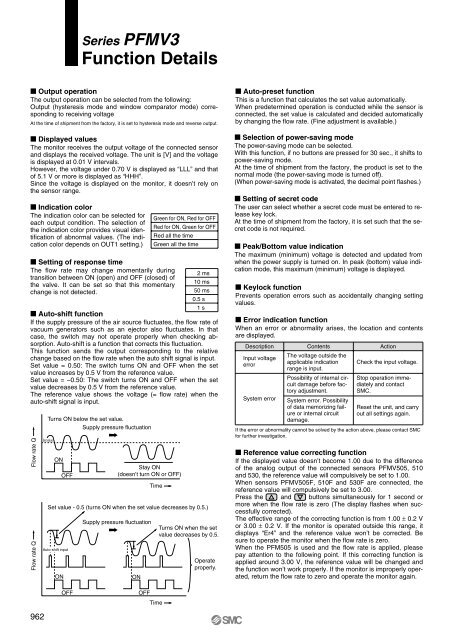
Series <strong>PFMV</strong>3Function Details Output operationThe output operation can be selected from the following:Output (hysteresis mode and window comparator mode) correspondingto receiving voltageAt the time of shipment from the factory, it is set to hysteresis mode and reverse output. Displayed valuesThe monitor receives the output voltage of the connected sensorand displays the received voltage. The unit is [V] and the voltageis displayed at 0.01 V intervals.However, the voltage under 0.70 V is displayed as “LLL” and thatof 5.1 V or more is displayed as “HHH”.Since the voltage is displayed on the monitor, it doesn’t rely onthe sensor range. Indication colorThe indication color can be selected foreach output condition. The selection ofthe indication color provides visual identificationof abnormal values. (The indicationcolor depends on OUT1 setting.)Green for ON, Red for OFFRed for ON, Green for OFFRed all the timeGreen all the time Setting of response timeThe flow rate may change momentarily during2 mstransition between ON (open) and OFF (closed) of10 msthe valve. It can be set so that this momentarychange is not detected.50 ms0.5 s1 s Auto-shift functionIf the supply pressure of the air source fluctuates, the flow rate ofvacuum generators such as an ejector also fluctuates. In thatcase, the switch may not operate properly when checking absorption.Auto-shift is a function that corrects this fluctuation.This function sends the output corresponding to the relativechange based on the flow rate when the auto shift signal is input.Set value = 0.50: The switch turns ON and OFF when the setvalue increases by 0.5 V from the reference value.Set value = –0.50: The switch turns ON and OFF when the setvalue decreases by 0.5 V from the reference value.The reference value shows the voltage (= flow rate) when theauto-shift signal is input.Flow rate QFlow rate QTurns ON below the set value.Supply pressure fluctuationSet valueONOFFAuto-shift inputONStay ON(doesn’t turn ON or OFF)Supply pressure fluctuationONTimeSet value - 0.5 (turns ON when the set value decreases by 0.5.)Turns ON when the setvalue decreases by 0.5.Operateproperly. Auto-preset functionThis is a function that calculates the set value automatically.When predetermined operation is conducted while the sensor isconnected, the set value is calculated and decided automaticallyby changing the flow rate. (Fine adjustment is available.) Selection of power-saving modeThe power-saving mode can be selected.With this function, if no buttons are pressed for 30 sec., it shifts topower-saving mode.At the time of shipment from the factory, the product is set to thenormal mode (the power-saving mode is turned off).(When power-saving mode is activated, the decimal point flashes.) Setting of secret codeThe user can select whether a secret code must be entered to releasekey lock.At the time of shipment from the factory, it is set such that the secretcode is not required. Peak/Bottom value indicationThe maximum (minimum) voltage is detected and updated fromwhen the power supply is turned on. In peak (bottom) value indicationmode, this maximum (minimum) voltage is displayed. Keylock functionPrevents operation errors such as accidentally changing settingvalues. Error indication functionWhen an error or abnormality arises, the location and contentsare displayed.Description Contents ActionInput voltageerrorSystem errorThe voltage outside theapplicable indicationrange is input.Possibility of internal circuitdamage before factoryadjustment.System error. Possibilityof data memorizing failureor internal circuitdamage.Check the input voltage.Stop operation immediatelyand contact<strong>SMC</strong>.Reset the unit, and carryout all settings again.If the error or abnormality cannot be solved by the action above, please contact <strong>SMC</strong>for further investigation. Reference value correcting functionIf the displayed value doesn’t become 1.00 due to the differenceof the analog output of the connected sensors <strong>PFMV</strong>505, 510and 530, the reference value will compulsively be set to 1.00.When sensors <strong>PFMV</strong>505F, 510F and 530F are connected, thereference value will compulsively be set to 3.00.Press the and buttons simultaneously for 1 second ormore when the flow rate is zero (The display flashes when successfullycorrected).The effective range of the correcting function is from 1.00 ± 0.2 Vor 3.00 ± 0.2 V. If the monitor is operated outside this range, itdisplays “Er4” and the reference value won’t be corrected. Besure to operate the monitor when the flow rate is zero.When the PFM505 is used and the flow rate is applied, pleasepay attention to the following point. If this correcting function isapplied around 3.00 V, the reference value will be changed andthe function won’t work properly. If the monitor is improperly operated,return the flow rate to zero and operate the monitor again.962OFFOFFTime