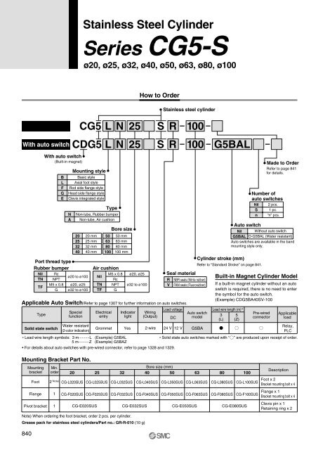
Stainless Steel CylinderSeries <strong>CG5</strong>-Sø20, ø25, ø32, ø40, ø50, ø63, ø80, ø100How to OrderWith auto switchWith auto switch(Built-in magnet)BLFGEMounting styleBasic styleAxial foot styleRod side flange styleHead side flange styleClevis integrated styleNAPort thread typeRubber bumperNilTNTFRcNPTM5 x 0.8GStainless steel cylinderCDG5 L N25 SR100 G5BAL20253240<strong>CG5</strong> L N 2520 mm25 mm32 mm40 mmTypeNon-lube, Rubber bumperNon-lube, Air cushionø20 to ø100ø20, ø25ø32 to ø100506380100Air cushionNilTNTFBore size50 mm63 mm80 mm100 mmM5 x 0.8RcNPTGø20, ø25ø32 to ø100SSeal materialRVR 100Applicable Auto Switch/Refer to page 1307 for further information on auto switches.TypeSolid state switchSpecialfunctionWater resistant(2-color indication)ElectricalentryGrommetIndicatorlightYesWiring(Output)2-wireNBR seals (Nitrile rubber)FKM seals (Fluororubber)Load voltageDC24 V 12 VAuto switchNil Without auto switchG5BAL D-G5BAL (Water resistant)Auto switches are available in the bandmounting style only.Cylinder stroke (mm)Refer to “Standard Stroke” on page 841.Auto switchmodelG5BALead wire length (m)∗3 5(L) (Z)∗ Lead wire length symbols: 3 m··········L (Example) G5BAL∗ Solid state auto switches marked with “5 m··········Z (Example) G5BAZ• For details about auto switches with pre-wired connector, refer to page 1328 and 1329.Made to OrderRefer to page 841for details.Number ofauto switchesNil 2 pcs.S 1 pc.n “n” pcs.Built-in Magnet Cylinder ModelIf a built-in magnet cylinder without an autoswitch is required, there is no need to enterthe symbol for the auto switch.(Example) CDG5BA40SV-100Pre-wiredconnectorApplicableloadRelay,PLC” are produced upon receipt of order.Mounting Bracket Part No.MountingbracketFootFlangePivot bracketMin.order2 Note)1120 25CG-L020SUSCG-F020SUSCG-L025SUSCG-F025SUSCG-E020SUSBore size (mm)32 40 50 63CG-L032SUSCG-F032SUSCG-E032SUSNote) When ordering the foot bracket, order 2 pcs. per cylinder.Grease pack for stainless steel cylinders/Part no.: GR-R-010 (10 g)CG-L040SUSCG-F040SUSCG-L050SUSCG-F050SUSCG-L063SUSCG-F063SUSCG-E050SUS80 100CG-L080SUSCG-F080SUSCG-E080SUSCG-L100SUSCG-F100SUSDescriptionFoot x 2Bracket mounting bolt x 4Flange x 1Bracket mounting bolt x 4Clevis pin x 1Retaining ring x 2840
Stainless Steel Cylinder Series <strong>CG5</strong>-SSpecificationsJIS SymbolDouble acting,Single rodBore size (mm)ActionFluidProof pressureMaximum operating pressureMinimum operating pressureAmbient and fluid temperatureCushionLubricationPiston speedStroke length toleranceMounting styleStandard Stroke20 25 32 40 50 63 80 100Double acting, Single rodAir1.5 MPa1.0 MPa0.05 MPaWithout auto switch: –10 to 70°C With auto switch: –10 to 60°CRubber bumper, Air cushionNot required (Non-lube)50 to 1000 mm/s 50 to 700 mm/sst + 1.4Up to 1000 mm,st + 1.4st + 1.50Up to 1000 0 mm, Up to 1200 0 mmst + 1.5Up to 1500 0 mmBasic style, Axial foot style, Rod side flange style,Head side flange style, Clevis integrated styleSymbol-XA-XB6Made to Order Specifications(For details, refer to pages 1380 and 1397.)SpecificationsChange of rod end shapeHeat resistant cylinder (150°C) ∗∗ Heat resistant grease (non-food grease) is used.Bore size (mm)2025324050, 6380100AccessoryMassStandard stroke25, 50, 75, 100, 125, 150, 20025, 50, 75, 100, 125, 150, 200250, 300MountingLong stroke201 to 350301 to 400301 to 450301 to 800301 to 1200301 to 1400301 to 1500Maximum manufacturable stroke∗ Manufacture of intermediate strokes at 1 mm intervals is possible. (Spacers are not used.)∗ Long stroke applies to the axial foot style and the rod side flange style. If other mounting brackets areused, or the length exceeds the long stroke limit, the stroke should be determined based on the strokeselection table (front matter 28, CG1).StandardequipmentOptionRod end nutSingle knuckle jointDouble knuckle joint (With pin & retaining ring)Pivot bracket (With pin and retaining ring)BasicstyleAxialfoot styleRod sideflange style(kg)Bore size (mm)Basic styleAxial foot styleFlange styleClevis integrated stylePivot bracketSingle knuckle jointDouble knuckle joint (with pin)Additional mass per each 50 mm of strokeAdditional mass with air cushion200.320.400.430.370.080.040.050.060.02250.420.530.530.480.080.070.090.080.02320.610.720.710.720.180.070.090.140.03400.971.131.121.120.180.110.180.180.02501.782.122.042.170.460.220.330.270.06632.733.193.253.260.460.220.330.330.07805.205.915.866.481.650.530.730.500.141008.139.509.299.941.650.781.070.730.16Calculation: (Example) <strong>CG5</strong>LA 20SR-100 • Basic mass································ 0.40 kg (Foot style ø20)(Foot style ø20, 100 stroke) • Additional stroke mass ············· 0.06 kg/50 ST• Air cylinder stroke······················ 100 ST• Additional air cushion mass ····· 0.02 kg0.40 + 0.06 x 100/50 + 0.02 = 0.54 kg841Basic mass1500Head sideflange styleClevisintegratedstyleCJ5<strong>CG5</strong>HYCMD--XIndividual-XTechnicaldata