COES Lab Report Template - Department of Mechanical and ...
COES Lab Report Template - Department of Mechanical and ...
COES Lab Report Template - Department of Mechanical and ...

Create successful ePaper yourself
Turn your PDF publications into a flip-book with our unique Google optimized e-Paper software.
Cantilever Support DesignDavid Bumgarner9-28-10MAE 415 <strong>Mechanical</strong> DesignAbstract:A cantilever support constructed <strong>of</strong> a column <strong>and</strong> a beam both made up <strong>of</strong> ½” ANSI 1020 HRsteel are being joined. Three methods <strong>of</strong> attachment were deemed acceptable after analysiscalculations were preformed. A welded connection was the first design. It is calculated for two6” long 3/16” fillet welds to be sufficient to bear the 6000 lb load in the specified weldingpattern. A bolted connection was the next option, this was found to be acceptable if two 3/8 in -16 UNC Grade 7 bolts were used in a vertical pattern. The final method <strong>of</strong> adjoining the twosteel parts is by using an adhesive. It is found through calculations <strong>and</strong> research that a specialtymixture <strong>of</strong> EPON Resin 580005 is capable <strong>of</strong> bearing the applied load. The recommendedmethod <strong>of</strong> joining the cantilever to the beam is by using the welded connection. This willprovide the strongest joint with the highest factor <strong>of</strong> safety which is 3.33 with just a 3/16” filletweld size.<strong>Mechanical</strong> <strong>and</strong> Aerospace Engineering<strong>Department</strong>iNC STATE UNIVERSITY
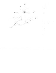
Cantilever Support DesignDavid Bumgarner9-28-10MAE 415 <strong>Mechanical</strong> DesignIt is determined to use a 3/16” weld for the most cost efficient weld while still maintaining asufficient safety factor <strong>of</strong> 3.33. All calculations can be seen in more detail in Appendix C.Bolted Connection AnalysisThe design <strong>of</strong> the bolted connection is intended to bear the 6000 lb load that is applied, as shownin Figure 1, yet not use more than 4 bolts. As you can see in Figure 6, the chosen designimplemented two bolts in a vertical pattern. The location <strong>and</strong> pattern <strong>of</strong> the bolts was selected inorder for the centroid <strong>of</strong> the bolt pattern to be located as close as possible to the line <strong>of</strong> action <strong>of</strong>the applied force to decrease the formed moment, all the while still maintaining ample column<strong>and</strong> cantilever support material around the bolt holes for added strength. A safety factor <strong>of</strong>n s = 1.2 was used throughout all calculations.yxFigure 6: Cantilever design with Bolt PatternThe primary <strong>and</strong> secondary shear forces must be accounted in the value for total shear for byusing Equation 12 <strong>and</strong> Equation 13 found in Shigley 1 .As seen in Figure 7, the forces act perpendicular to each other, therefore the sum <strong>of</strong> them will usethe Pythagorean Theorem, Equation 14. Both bolts have the same force on them, so forces inboth bolts will be critical to the design <strong>of</strong> this joint.(12)(13)<strong>Mechanical</strong> <strong>and</strong> Aerospace Engineering<strong>Department</strong>5NC STATE UNIVERSITY
Cantilever Support DesignDavid Bumgarner9-28-10MAE 415 <strong>Mechanical</strong> DesignF’F’’F’F’’yxFigure 7: Cantilever Design with Component Bolt Forces Shown(14)The length <strong>of</strong> the bolts are determined from equation 8-13 <strong>and</strong> from an equation found in Table8-7(Shigley 1 ) <strong>and</strong> are listed as Equation 15 <strong>and</strong> Equation 16, respectively.To determine the minimum diameter for the bolt, the bearing <strong>and</strong> bending in the members arecalculated using Equation 17 <strong>and</strong> 18 from Shigley 1 , respectively.After a st<strong>and</strong>ard bolt size <strong>of</strong> 3/8” is decided upon, the following equations implement that sizebolt into the calculations to determine what grade <strong>of</strong> bolt is required to maintain an adequatesafety factor throughout the entire joint connection. The bearing in the bolts, Equation 19, <strong>and</strong>the shear <strong>of</strong> the bolts, Equation 20, from Shigley 1 , are used to determine the minimum pro<strong>of</strong>strength <strong>of</strong> the bolts.The final design was made with the bolts being 3/8 in – 16 UNC Grade 7 with nuts tightened to30 ft-lb. This is determined by using the recommended bolt torque specifications listed inEngineer’s H<strong>and</strong>book 3 . The listed torque for the chosen bolts is 44 ft-lb, but the 30 ft-lb willallow a safety factor <strong>of</strong> 1.47. By using SAE Grade 7 bolts, the pro<strong>of</strong> strength <strong>of</strong> these boltsoutweighs the necessary strength, therefore the factor <strong>of</strong> safety in the bolts is greater than thespecified n s = 1.2 used throughout the problem. The actual factor <strong>of</strong> safety using SAE Grade 7bolts is n s =1.46. All calculations are shown in Appendix D.(15)(16)(17)(18)(19)(20)<strong>Mechanical</strong> <strong>and</strong> Aerospace Engineering<strong>Department</strong>6NC STATE UNIVERSITY
Cantilever Support DesignDavid Bumgarner9-28-10MAE 415 <strong>Mechanical</strong> DesignAdhesive Connection AnalysisIn a connection bonded with adhesive, one <strong>of</strong> the most important variables is choosing thecorrect adhesive. That will bond to the materials present in the joint <strong>and</strong> also that will hold up tothe applied amount <strong>of</strong> stress. Figure 8 shows how the adhesive is planned to be laid out. It is acircle with a 4.6” diameter.yxFigure 8: Cantilever Design with Adhesive PatternThere will be aspects <strong>of</strong> both direct shear <strong>and</strong> shear produced by the moment, which will act onthe adhesively bonded joint. The primary shear acts on the joint due to the force that is applied<strong>and</strong> the secondary shear results from the moment that the load causes on the joint. To calculatethese components <strong>of</strong> shear, Equation 21 <strong>and</strong> Equation 22 are used from Shigley 1 .To combine these components <strong>of</strong> shear, in order to calculate the total stress that is acting on thejoint, refer to Figure 9.(21)(22)yxFigure 9: Cantilever Design with Components <strong>of</strong> Stress Shown<strong>Mechanical</strong> <strong>and</strong> Aerospace Engineering<strong>Department</strong>7NC STATE UNIVERSITY
Cantilever Support DesignDavid Bumgarner9-28-10MAE 415 <strong>Mechanical</strong> DesignThe primary shear, τ’, acts in the downward direction over the entire area <strong>of</strong> adhesive while thesecondary shear, τ’’, acts only tangent to the circular pattern in a clockwise direction. Therefore,as you can see at the point at the right most edge <strong>of</strong> the adhesive circle in Figure 9, the shearstresses will be a maximum <strong>and</strong> can be added directly since the will be acting in the samedirection. From this figure Equation 23 can be derived.(23)The next task is finding the correct adhesive, that will bond to the ANSI 1020 HR steel <strong>of</strong> whichboth pieces <strong>of</strong> the joint are constructed <strong>and</strong> bear the amount <strong>of</strong> stress that will be applied due tothe shear stress <strong>of</strong> τ = 2653.77 psi that was calculated.The most effective adhesive that was found for this application was made by Hexion SpecialtyChemicals 2 . The highest factor <strong>of</strong> safety was desired since adhesives can be very sensitive tomany types <strong>of</strong> user error. The adhesive that was chosen for the application is a mixture. Itcontains 75 parts by weight (pbw) <strong>of</strong> EPON Resin 828, 25 pbw EPON Resin 580005, <strong>and</strong> 6 pbwDicy<strong>and</strong>iamide for curing purposes. This adhesive is to cure for 2 hours at 93 o C <strong>and</strong> then for 2hours at 150 o C. After this process, the adhesive is rated at 5,230 psi when in shear. Thisprovides a safety factor <strong>of</strong> 1.89.Detailed calculations are shown in Appendix E <strong>and</strong> specifications on the chosen adhesive arelocated in Appendix F.Conclusions <strong>and</strong> RecommendationsIn order to meet <strong>and</strong> exceed the required strength <strong>of</strong> the cantilever joint there are three feasiblesolutions. The weld is determined to be suitable to connect the joint with any fillet size between3/16” <strong>and</strong> 1/2” while using the E6012 electrode. The bolted connection is found to be sufficientby using two 3/8 in – 16 UNC Grade 7 bolts. This provides a factor <strong>of</strong> safety <strong>of</strong> 1.46. Theconnection will be stable as well with an adhesively bonded joint by using the specializedmixture <strong>of</strong> EPON Resin 580005. The adhesively bonded joint will have a 1.89 safety factor.After all things are taken into account the welded connection, with a 3/16” fillet weld size, isrecommended due to the highest factor <strong>of</strong> safety <strong>of</strong> 3.33.<strong>Mechanical</strong> <strong>and</strong> Aerospace Engineering<strong>Department</strong>8NC STATE UNIVERSITY
Cantilever Support DesignDavid Bumgarner9-28-10MAE 415 <strong>Mechanical</strong> DesignReferences1. Budynas, Richard G., <strong>and</strong> Nisbett, J. Keith. Shigley's <strong>Mechanical</strong> Engineering Design.New York: McGraw-Hill, 2011. Print.2. "Hexion.com - EPON Resin 58005." Hexion.com - Binding, Bonding <strong>and</strong> Coating withThermoset Resins. Sept. 2001. Web. 28 Sept. 2010..3. "Steel Bolt Torque Specifications Table - Engineer's H<strong>and</strong>book." <strong>Mechanical</strong>Engineering Design Guide - Engineer's H<strong>and</strong>book. 2006. Web. 18 Oct. 2010..Appendix A – ConstantsS ut = 55ksi (Table A-20, Shigley 1 )S y(mem) = 30 ksi (Table A-20, Shigley 1 )S T = 62 ksi (Table 9-3, Shigley 1 )S Y = 50 ksi (Table 9-3, Shigley 1 )S P = 55 ksi (Table 8-9, Shigley 1 )H = 21/64” (Table A-31, Shigley 1 )Appendix B – NomenclatureS ut – ultimate strength <strong>of</strong> base metalS y(mem) – yield strength <strong>of</strong> base metalS T – ultimate strength <strong>of</strong> weld metalS Y – yield strength <strong>of</strong> weld metalA – weld areah – height (size) <strong>of</strong> fillet weldb – length <strong>of</strong> weldc – length <strong>of</strong> weld– component <strong>of</strong> centroid– component <strong>of</strong> centroidJ – polar moment <strong>of</strong> inertiaτ – shear stressτ all – allowable shear stressM – momentr – radiusd – diametert – thickness <strong>of</strong> plateV – shear forcen s – factor <strong>of</strong> safetyS P – pro<strong>of</strong> strength <strong>of</strong> steel boltL T – threaded length <strong>of</strong> boltL – total length <strong>of</strong> boltH – height <strong>of</strong> nut<strong>Mechanical</strong> <strong>and</strong> Aerospace Engineering<strong>Department</strong>9NC STATE UNIVERSITY
Cantilever Support DesignDavid Bumgarner9-28-10MAE 415 <strong>Mechanical</strong> DesignAppendix C – Welded Joint CalculationsThe allowable shear stress is 12 ksi since it is the minimum τ max value.<strong>Mechanical</strong> <strong>and</strong> Aerospace Engineering<strong>Department</strong>10NC STATE UNIVERSITY
Cantilever Support DesignDavid Bumgarner9-28-10MAE 415 <strong>Mechanical</strong> DesignAppendix D – Bolted Joint Calculations<strong>Mechanical</strong> <strong>and</strong> Aerospace Engineering<strong>Department</strong>11NC STATE UNIVERSITY
Cantilever Support DesignDavid Bumgarner9-28-10MAE 415 <strong>Mechanical</strong> DesignBolts 1.5” long were chosen so that the threaded length <strong>of</strong> the bolt would not be in shear.The minimum st<strong>and</strong>ard size bolt that is applicable in this base metal is 3/8”, therefore that sizewas chosen to minimize the size <strong>of</strong> the bolt.44100 psi<strong>Mechanical</strong> <strong>and</strong> Aerospace Engineering<strong>Department</strong>12NC STATE UNIVERSITY
Cantilever Support DesignDavid Bumgarner9-28-10MAE 415 <strong>Mechanical</strong> DesignRefer to Table 8-9 (Shigley 1 ) to determine the SAE grade <strong>of</strong> bolt needed.Appendix E – Adhesively Bonded Joint CalculationsResearch was done in the internet to find an adhesive to bear this amount <strong>of</strong> shear stress. Moreinformation can be found in Appendix F for this adhesive.<strong>Mechanical</strong> <strong>and</strong> Aerospace Engineering<strong>Department</strong>13NC STATE UNIVERSITY
Cantilever Support DesignDavid Bumgarner9-28-10MAE 415 <strong>Mechanical</strong> DesignAppendix F – EPON Resin 580005 Technical Data Sheet (Hexion 2 )Re-issued September 2001EPON Resin 580005Product DescriptionEPON Resin 580005 is an elastomer modified epoxy functional adduct formed from thereaction <strong>of</strong> the diglycidyl ether <strong>of</strong> bisphenol A <strong>and</strong> a carboxyl terminated butadiene-acrylonitrileelastomer. Elastomer content is approximately 40% by weight. Primary use <strong>of</strong> EPON 58005 isthe modification <strong>of</strong> conventional epoxy systems to increase flexibility, adhesion properties <strong>and</strong>fatigue resistance.Application Areas/Suggested UsesHigh performance adhesives, featuring:BenefitsHigher peel <strong>and</strong> shear strengthsThermal shock resistanceGreater fatigue resistanceFatigue resistant composite structuresHigh elastomer content – convenient adjustment <strong>of</strong> elastomer contentCompatible with a wide range <strong>of</strong> liquid epoxy resinsImparts improved peel strength <strong>and</strong> fatigue resistance with minimal reduction <strong>of</strong> stiffness<strong>and</strong> maximum operating temperatureSales SpecificationProperty Units Value Test Method/St<strong>and</strong>ardEpoxide Equivalent Weight g/eq 325 – 375 ASTM D1652Viscosity at 25°C P 3,000 – 8,000 ASTM D2196Color Gardner 11 max. ASTM D1544AppearanceClear to SlightHazy Liquid<strong>Mechanical</strong> <strong>and</strong> Aerospace Engineering<strong>Department</strong>14NC STATE UNIVERSITY
Cantilever Support DesignDavid Bumgarner9-28-10MAE 415 <strong>Mechanical</strong> DesignTypical PropertiesProperty Units Value Test Method/St<strong>and</strong>ardDensity at 25°C lb/gal 9.0 ASTM D1475General InformationAs a result <strong>of</strong> a relatively high acrylonitrile content, EPON 580005 is compatible with mostepoxy resin types, including bisphenol F <strong>and</strong> novolac epoxies, within the typically used range <strong>of</strong>concentrations (
Cantilever Support DesignDavid Bumgarner9-28-10MAE 415 <strong>Mechanical</strong> DesignTable 1 / Effect <strong>of</strong> EPON Resin 580005 concentration on properties <strong>of</strong> an epoxy systemMethod Units A B C D EEPON Resin 58005 pbw --- 12.5 25 37.5 50EPON Resin 828 pbw 100 87.5 75 62.5 50EPIKURE Curing Agent3072pbw 35 33 30 29 27H<strong>and</strong>ling Properties @25°CInitial viscosity cP 4,000 7,720 13,700 21,200 32,200Gel Time, 100 gram mass minutes 43 48 51 61 73Cure Schedule wk/°C 1/25 1/25 1/25 1/25 1/25Cured State Properties 1Tensile StrengthASTMD638Aluminum/Aluminum psi 2,000 2,060 2,760 4,020 3,960Steel/Steel psi 2,600 3,700 3,880 4,290 3,91090° Peel StrengthAluminum/Aluminum lbs/inch 2-3 4-6 10-12 14-16 20-22Hardness Shore D 86 85 84 81 801 Determined at 23 °C following one week cure at 25 °C.Being epoxy functional, EPON 580005 can be cured with converters commonly used inconventional epoxy systems. Due to its higher weight per epoxide, adjustment <strong>of</strong> curing agentlevel should normally coincide with incorporation <strong>of</strong> this modifier resin. Effect <strong>of</strong> EPON 580005incorporation on the properties <strong>of</strong> st<strong>and</strong>ard systems cured with a representative aliphatic amine,aromatic amine, <strong>and</strong> a catalytic curative is indicated by Table 2 data. The high viscosity <strong>of</strong>EPON 58005 will normally necessitate that this resin be heated in order to facilitate pumping orblending operations. Figure 2 provides guidance as to the reduction in product viscosity resultingfrom increasing temperatures within the 75 - 190 °F range.<strong>Mechanical</strong> <strong>and</strong> Aerospace Engineering<strong>Department</strong>16NC STATE UNIVERSITY
Cantilever Support DesignDavid Bumgarner9-28-10MAE 415 <strong>Mechanical</strong> DesignTable 2 / Effect <strong>of</strong> EPON Resin 580005 on adhesive properties <strong>of</strong> various systemsMethod Units A B C 1 DEPON Resin 828 pbw 100 62.5 100 75EPON Resin 58005 pbw --- 37.5 --- 25EPIKURE Curing Agent3234pbw 13 11 --- ---Dicy<strong>and</strong>iamide pbw --- --- 6 6Cure Schedule wk/°C 1/25 1/25 2hrs/93 +2hrs/1502hrs/93 +2hrs/150Cured State Properties 2Tensile StrengthASTM D638Aluminum/Aluminum psi 1,520 3,270 2,530 4,150Steel/Steel psi 2,610 4,100 5,100 5,23090° Peel StrengthAluminum/Aluminum lbs/inch 0.5-1.0 5.0 --- ---Hardness Shore D 88 70 --- ---1 System modified with 2 phr Cab-O-Sil M-5 to retain suspension <strong>of</strong> dicy<strong>and</strong>iamide throughgelation. Cab-O-Sil is a registered trademark <strong>of</strong> Cabot Corporation.2 Determined at 23 °C. Systems A <strong>and</strong> B cured one week at 25 °C. Systems C <strong>and</strong> D cured twohours at 93 °C plus two hours at 150 °C.<strong>Mechanical</strong> <strong>and</strong> Aerospace Engineering<strong>Department</strong>17NC STATE UNIVERSITY
Cantilever Support DesignDavid Bumgarner9-28-10MAE 415 <strong>Mechanical</strong> DesignFigure 2 / EPON Resin 580005 Viscosity vs. TemperatureSafety, Storage & H<strong>and</strong>lingPlease refer to the MSDS for the most current Safety <strong>and</strong> H<strong>and</strong>ling information.Please refer to the Hexion web site for Shelf Life <strong>and</strong> recommended Storage information.Exposure to these materials should be minimized <strong>and</strong> avoided, if feasible, through theobservance <strong>of</strong> proper precautions, use <strong>of</strong> appropriate engineering controls <strong>and</strong> proper personalprotective clothing <strong>and</strong> equipment, <strong>and</strong> adherence to proper h<strong>and</strong>ling procedures. None <strong>of</strong> thesematerials should be used, stored, or transported until the h<strong>and</strong>ling precautions <strong>and</strong>recommendations as stated in the Material Safety Data Sheet (MSDS) for these <strong>and</strong> allother products being used are understood by all persons who will work with them.Questions <strong>and</strong> requests for information on Hexion Specialty Chemicals, Inc. ("Hexion") productsshould be directed to your Hexion sales representative, or the nearest Hexion sales <strong>of</strong>fice.<strong>Mechanical</strong> <strong>and</strong> Aerospace Engineering<strong>Department</strong>18NC STATE UNIVERSITY
Cantilever Support DesignDavid Bumgarner9-28-10MAE 415 <strong>Mechanical</strong> DesignInformation <strong>and</strong> MSDSs on non-Hexion products should be obtained from the respectivemanufacturer.PackagingAvailable in bulk <strong>and</strong> drum quantities.Contact InformationFor product prices, availability, or order placement, call our toll-free customer service number at:1-877-859-2800For literature <strong>and</strong> technical assistance, visit our website at: www.hexion.com® <strong>and</strong> Licensed trademarks <strong>of</strong> Hexion Specialty Chemicals, Inc.DISCLAIMERThe information provided herein was believed by Hexion Specialty Chemicals (“Hexion”) to beaccurate at the time <strong>of</strong> preparation or prepared from sources believed to be reliable, but it is theresponsibility <strong>of</strong> the user to investigate <strong>and</strong> underst<strong>and</strong> other pertinent sources <strong>of</strong> information, tocomply with all laws <strong>and</strong> procedures applicable to the safe h<strong>and</strong>ling <strong>and</strong> use <strong>of</strong> the product <strong>and</strong>to determine the suitability <strong>of</strong> the product for its intended use. All products supplied by Hexionare subject to Hexion’s terms <strong>and</strong> conditions <strong>of</strong> sale. HEXION MAKES NO WARRANTY,EXPRESS OR IMPLIED, CONCERNING THE PRODUCT OR THEMERCHANTABILITY OR FITNESS THEREOF FOR ANY PURPOSE ORCONCERNING THE ACCURACY OF ANY INFORMATION PROVIDED BY HEXION,except that the product shall conform to Hexion’s specifications. Nothing contained hereinconstitutes an <strong>of</strong>fer for the sale <strong>of</strong> any product.<strong>Mechanical</strong> <strong>and</strong> Aerospace Engineering<strong>Department</strong>19NC STATE UNIVERSITY