LIT-060 Hunter 2004-2005 Product Catalog - Ewing Irrigation
LIT-060 Hunter 2004-2005 Product Catalog - Ewing Irrigation
LIT-060 Hunter 2004-2005 Product Catalog - Ewing Irrigation

You also want an ePaper? Increase the reach of your titles
YUMPU automatically turns print PDFs into web optimized ePapers that Google loves.
ROTORSPGJ ____________________________________________________________ 6PGP ® ___________________________________________________________ 8I-10/I-20 Ultra ___________________________________________________ 12I-25/31 Plus_____________________________________________________ 16I-40/41 Group ___________________________________________________ 20I-60 ___________________________________________________________ 24I-90 ___________________________________________________________ 26SPRAYSPS ____________________________________________________________ 30SRS___________________________________________________________ 34Pro-Spray ® ______________________________________________________ 36Institutional Spray ________________________________________________ 38Adjustable Arc Nozzles ____________________________________________ 40Fixed Pattern Nozzles _____________________________________________ 42Specialty Nozzles_________________________________________________ 44Bubblers and Bubbler Nozzles_______________________________________ 46VALVESSRV___________________________________________________________ 50ASV/AVB _______________________________________________________ 52PGV___________________________________________________________ 54PGV Jar-Top ____________________________________________________ 56HPV___________________________________________________________ 58ICV ___________________________________________________________ 60ICV Filter Sentry _________________________________________________ 62HBV___________________________________________________________ 64CONTROLLERSSRC___________________________________________________________ 66EC ____________________________________________________________ 68Pro-C__________________________________________________________ 70ICC Plastic______________________________________________________ 72ICC Metal_______________________________________________________ 74IDS ___________________________________________________________ 76ICR Remote_____________________________________________________ 78SRR Remote ____________________________________________________ 79SVC – Smart Valve Controller _______________________________________ 80Wireless Valve System ____________________________________________ 81CENTRAL CONTROLSIMMS - <strong>Irrigation</strong> Management and Monitoring System__________________ 84ICC-SAT________________________________________________________ 88SENSORSMini-Clik ® _______________________________________________________ 92Rain-Clik ______________________________________________________ 94Wireless Rain-Clik _______________________________________________ 95Freeze-Clik ® /Wind-Clik ® /Mini-Weather Station ___________________________ 96Flow-Clik _______________________________________________________ 97MISCELLANEOUS PRODUCTSSJ Swing Joint/<strong>Hunter</strong> Flexible Tubing/<strong>Hunter</strong> Spiral Barb Elbows __________ 100HCV Check Valve/PSR Pump Relay __________________________________ 101Accessories ____________________________________________________ 102TECHNICAL INFORMATIONDesign Resources _______________________________________________ 104Precipitation Rates ______________________________________________ 105Conversion Factors ______________________________________________ 106Slope Equivalents/Slope <strong>Irrigation</strong>___________________________________ 107Replacement Guide ______________________________________________ 108Installation Guide _______________________________________________ 111Height of Spray _________________________________________________ 114Friction Loss Charts _____________________________________________ 115Additional Data _________________________________________________ 125IMMS Connections _____________________________________________ 126Wire Sizing ____________________________________________________ 128Warranty ______________________________________________________ 129
Call it what you will, it’s simply the only way we know howto do business here at <strong>Hunter</strong>. For us, just good enough isnever enough.From the performance of our products to the performanceof our people, we are never satisfied simply to meetstandards…we strive to surpass them. In our more than20 years of working for you in the field of irrigation, wehave come to learn it is that kind of commitment to ourcustomers and our craft that has helped to turn us from asmall upstart into an industry leader.And, as a leader we will continueto expand our presence, withour mission to be the landscapeprofessional’s first choice forirrigation products and services.We have dedicated ourselves to focus on the needs ofthe professional user in all our efforts and, as always, willremain committed to giving you more than you expect.1
THE HIGHEST QUA<strong>LIT</strong>Y PRODUCTSFrom gardens to golf courses, fromcustom homes to campuses, from shoppingcenters to sports fields…we’ve developeda full line-up of top quality irrigationproducts for virtually every application.And even before our very first rotor cameoff the line more than two decades ago,quality has been our primary concern.At <strong>Hunter</strong>, we’re problem solvers, with agoal of providing innovative solutions forthe people in the field who use our productsevery day. That role began with thePGP ® – the industry’s most-often-imitated,yet never duplicated product. It has continuedwith the latest generation of imaginativecreations, including modular controllers(ICC and Pro-C), the revolutionaryFloStop ® (I-20 Ultra), and easy-to-servicevalves (PGV Jar-Top).What sets all these products apart from thecompetition is the extra effort we put intotesting. At our on-site labs, both indoorsand out. Under extreme temperatures andpressures. And, ultimately, with actual endusersfor their evaluations before the productsare even approved for production.And when production does take place,we test all throughout the manufacturingprocess – from molding to assembly – toensure quality is assembled in, rather thansimply inspected at the end of the line.The most stringent and diverse testingprocedures in the irrigation industry havegiven <strong>Hunter</strong> products a level of qualitythat is the envy of the competition.PEOPLE WHO TRULY UNDERSTAND IRRIGATIONCEO Richard <strong>Hunter</strong> takes an active role inthe day-to-day operations of the company.It’s more than simply knowing our line ofwork, it’s being in tune with the needs anddesires of our industry’s professionals. Wewant to know all we can about the day-todaychallenges that face our customers andhow our products can provide solutions.And the fact that so many of our peoplepossess years of personal experience ascontractors, specifiers or distributors onlyhelps to make the bond with our customersthat much stronger.No coincidence then that so many of ourideas for both new products and enhancementsto existing ones come from out inthe field. We value the experience of thosewho work hands on with irrigation, soour experienced professionals seek outthe input of industry professionals likeyou before the development process evenbegins. It is that feedback that has helpedus to create the products that you wantand you need.At <strong>Hunter</strong>, understanding irrigationstarts at the top, but by no means does itend there. Our company leader, Richard<strong>Hunter</strong>, is an engineer himself and assuch keeps closely in touch with all facetsof product production, from the earliestconcepts through the time the finishedgoods ship out our doors. While at eachstep of the way along that product trail,he is surrounded by a team of dedicatedindividuals who know our industry andits people better than anyone.2
SUPPORT YOU NEED TO BE MORE SUCCESSFULProud as we are of our products, we at<strong>Hunter</strong> also know that our success isdependent upon so much more. It’s builtupon your success. So we go out of ourway to do whatever it takes to help makeyour business the best it can be.Take, for example, the <strong>Hunter</strong> PreferredContractor Program. It’s the only frequentbuyer program in the industry that helpsyou buy the equipment you need, advertiseand promote your services, and providetraining for your personnel. All to helpyou create a more efficient and fast-growingbusiness.Our DATA Line puts design recommendations,programming solutions and installationassistance just a phone call away.We also provide plenty of informationthat professionals can use (from technicalupdates to tips on improving your business)in our periodic mailingsand newsletters.And more! How about a website designed around industryprofessionals and teeming withvaluable resources. A widearray of computer softwareand a full complement ofhelpful printed materials forour complete line of products.Advanced education offeredthroughout the year at the<strong>Hunter</strong> Institute of <strong>Irrigation</strong> and“on the road” in selected marketsaround the country.Simply put, no other company inthe industry provides the kind ofongoing support that <strong>Hunter</strong> does.Contractors in thefield can call <strong>Hunter</strong>’sDATA Line forinformative solutionsto design andinstallation dilemmas.From designing a system to improving a company’s cash flow,<strong>Hunter</strong>’s informative, interactive workshops focus on manyaspects of the irrigation professional’s business.3
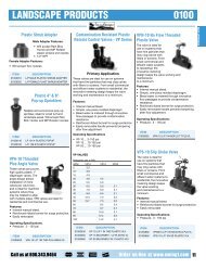
PGJAll the features and benefits of the PGP ® ,scaled down to fit typical spray applications.Arack of easy-to-install-and-change, water-efficient nozzles…just likePGP. Easy adjustment from the top of the sprinkler…just like PGP.The safety and durability of a rubber cover…just like PGP. The PGJis a chip off the ol’ block, in essence a PGP “junior.” <strong>Hunter</strong> has scaleddown the world’s top-selling sprinkler exclusively for use in applicationsthat typically call for a spray but where it’s now possible to have all thebenefits of a rotor. The PGJ is capable of working in tandem with largerrotors to combine big and small areas in a single zone, offering a convenienceand efficiency that sprays do not. With PGJ, fewer heads performmore efficient work for a more economical price.The “scaled down” rotor and spray alternativedesigned for mid-range areas at residential andcommercial sites.FEATURES & BENEFITSRadius adjustment screwAllows fine tuning of spray, ensurespositive nozzle retention, can't be lostProtective rubber coverKeeps debris out40°– 360° adjustable arcEasily adjustable from top of sprinkler,up, down, wet or dryWater-lubricated gear driveTime proven, reliable rotation,year after yearVariable statorKeeps rotation speed consistentregardless of nozzle size or pressureExtra large filter screenTraps more debris without cloggingOptional factory-installeddrain check valvePrevents wet spots, caused by lowhead drainageMODELSPGJ-00 – ShrubPGJ-04 – 4" Pop-up (10 cm)PGJ-06 – 6" Pop-up (15 cm)PGJ-12 – 12" Pop-up (30 cm)DIMENSIONS• Overall height:PGJ-00 – 7" (18 cm)PGJ-04 – 7 1 ⁄8" (18 cm)PGJ-06 – 9 1 ⁄8" (23 cm)PGJ-12 – 16 3 ⁄8" (41 cm)• 1⁄2" female inlet NPT• Exposed diameter: 1 1 ⁄8" (3 cm)OPERATING SPECIFICATIONS• Discharge rate: .64 to 5.3 GPM(0.15 to 1.2 m 3 /hr; 2.4 to 20.1 l/min)• Radius: 15' to 37' (4.6 to 11.3 m)• Recommended pressure range:30 to 50 PSI(2.1 to 3.4 bars; 206 to 344 kPa)• Precipitation rates:approximately 0.60" (16 mm)per hour at 40 PSI (2.8 bars; 275 kPa)for spacings from 16' to 37'(4.6 to 11.3 m)• Nozzle trajectory: approximately 14˚OPTIONS AVAILABLE• Drain check valve (Pop-upmodels only) for up to 7' (2.1 m)elevation change• Reclaimed water cover6
ROTORSSPRAYS? OR TIME-SAVING, MONEY-SAVING, WATER-SAVING ROTORS?When your landscape has mid-range zones that are long and narrow, the obviouschoice would be to install sprays. Yet, the intelligent choice would be a rotor specificallydesigned to fit this kind of landscape. With the scaled-down-in-size PGJ, two rowsof rotors can do the same job as three rows of spray heads. Because PGJ rotors canrun on the same zone as other rotary sprinklers, they require fewer valves and stations,and, in turn, less trenching, piping and labor. It all adds up to less installation time andlower installation costs (as well as lower watering costs). Note: All precipitation rates calculated for 180 degree operation.For the precipitation rate of a 360 degree sprinkler, divide by 2. For more information on precipitation rates see page 105.Heavy duty rubber cover keepsdebris out of adjustment mechanism.S P E C I F I C A T I O N G U I D EEXAMPLE: PGJ - 06 - VMODELPGJPOP-UP HEIGHT00 = Shrub04 = 4" Pop-up06 = 6" Pop-up12 = 12" Pop-upOPTIONSR = Reclaimed Water IdentifierV = Factory-Installed Drain Check Valve(Pop-up Models Only)Large PGJ nozzles are easy to identify,as well as easy to install and remove.7
PGP ®The world’s best selling residential and light commercial rotorsets the standards for an entire industry.Why settle for second best when you can have thesprinkler by which everything else is measured. ThePGP ® is <strong>Hunter</strong>’s original product, the item that putthe company on the map in 1981. Its exceptional design andimpressive performance placed the rotor a cut above backthen, while continuous improvements and enhancements haveallowed it to remain the number one selling rotor in the worldever since. With the superior ability to deliver even waterdistribution from precision engineered nozzles, this sprinkleris unequaled for reliability, durability, versatility and value.With its patented features and <strong>Hunter</strong>’s years of experiencein gear-drive technology, it’s no wonder the PGP remains theprofessional’s choice.With an over 20-yeartrack record, the PGP isthe world’s best sellingrotary sprinkler.FEATURES & BENEFITSIntegral rubber coverKeeps dirt out, won’t fall offComplete set ofinterchangeable nozzles12 standard or 7 low-angle nozzles forvirtually any task40°– 360° adjustable arc orfull-circle versionsFor fastest, hassle-free adjustment,wet or dryProven, long-life, water-lubricatedgear driveFirst introduced over 20 years ago andstill continuously improvedVariable statorKeeps rotation speed consistentregardless of nozzle size or pressureLarge dirty water screenPuts an end to nozzle cloggingMODELSPGS – ShrubPGP – 4" Pop-up (10 cm)PGH – 12" Pop-up (30 cm)PGP-ATR – 21⁄4" Pop-up – Retrofitsexisting Rain Bird ® Maxi-PAWand othersDIMENSIONS• Overall height:PGS – 7 3 ⁄8" (19 cm)PGP – 7 3 ⁄8" (19 cm)PGH – 17" (43 cm)• 3⁄4" female inlet NPT• Exposed diameter: 13⁄4" (4 cm)OPERATING SPECIFICATIONS• Discharge rate: .5 to 14.1 GPM(0.11 to 3.20 m 3 /hr; 1.9 to 53.4 l/min)• Radius: 22' to 52' (6.7 to 15.8 m)• Recommended pressure range:30 to 70 PSI(2.1 to 4.8 bars; 206 to 482 kPa)• Precipitation rates: approximately.4" (10 mm) per hour at 50 PSI(3.4 bars; 344 kPa) for spacings from25' to 45' (7.6 to 13.7 m)• Nozzle trajectory: standard – 25˚,low angle – 13˚OPTIONS AVAILABLE• Drain check valve for up to 10'(3.0 m) elevation change(not available for PGP-ATR)• Reclaimed water identification cover• Low angle nozzles• Factory-installed nozzle8
ROTORSSUPERIOR NOZZLE PERFORMANCE ENSURED THROUGH CONTINIOUS TESTINGWith a combination of intelligent planning, carefully controlled manufacturing andfrequent testing that conforms to the strictest industry standards, the exceptionalperformance of our nozzles is no accident. <strong>Hunter</strong> is the only rotary sprinklermanufacturer that not only tests nozzles during the development stage but also performsfrequent tests of every batch produced. In addition, the Center for <strong>Irrigation</strong>Technology in Fresno, California, independently tests our nozzles to provide thirdparty verification of their superior results.PGP-ATR: EASILY UPGRADE IMPACT SPRINKLERS TO MODERN GEAR DRIVE TECHNOLOGYLooking for an easy maintenance, high performance alternativeto the grit, contamination and tampering problems commonto impact sprinklers? <strong>Hunter</strong>ʼs PGP-ATR is the easy way toupgrade existing impact heads to modern gear drive technology.It takes only minutes to install. No digging required!3. Set wateringpattern todesired arc.1. Remove internalassembly ofexisting sprinkler.4. Install capportion ofATR.Installs Easily Without Disrupting Turf2. Thread entire ATRbody/riser intocanister.5. Or, make itinvisible byfilling the cupwith sod.9
PGP ®The world’s best selling residential and light commercial rotorsets the standards for an entire industry.Heavy duty retraction springensures positive retraction,time after time.Easy, “throughthe-top”arcand radiusadjustment.Proven, long life,water lubricatedgear drive.Introduced over20 years ago andstill continuouslyimproved.PGP handlesdirty water witha larger areafilter screen. Note:All precipitationrates calculated for 180 degree operation.For the precipitation rate of a 360 degree sprinkler, divide by 2.For more information on precipitation rates see page 105.12 standardtrajectorynozzles areincluded witheach sprinkler.A separaterack of lowangle nozzles isavailable.10
Both the 12" pop-up PGH and risermounted PGS (inset, shown with HCVcheck valve) sprinklers are ideal forirrigating shrub areas and slopes.ROTORS Note: All precipitation rates calculated for 180 degree operation.For the precipitation rate of a 360 degree sprinkler, divide by 2.For more information on precipitation rates see page 105.S P E C I F I C A T I O N G U I D EEXAMPLE: PGP - ADJ - LAMODELPGS = ShrubPGP = 4" Pop-upPGH = 12" Pop-upFEATURESADJ, 360, ADV, 36V, ARV, 3RVADJ, 360, ADV, 36V, ARV, 3RVADV, 36V, ARV, 3RVOPTIONSXX = 12 Standard Nozzles OR:LA = 7 Low-Angle Nozzles01 – 12 = Factory-Installed Standard Nozzle4 – 10 LA = Factory-Installed Low-Angle NozzleIntegral rubber coverprotects adjustmentmechanism and addssafety in play areas.ATRKEY TO FEATURES:ADJ = Adjustable with no Check Valve360 = Full-Circle with no Check ValveADV = Adjustable with Check ValveATR = 21⁄4" Pop-up, adjustable with no checkvalve and #7 nozzle factory-installed36V = Full-Circle with Check ValveARV = Adjustable, Reclaimed Water, with Check Valve3RV = Full-Circle, Reclaimed Water, with Check ValveWHAT MAKES PGP THE WORLD’S #1 GEAR DRIVE?The PGP ® has been and continues to be the world’s best-selling gear-driven rotary sprinkler. But beingfirst is not simply limited to sales figures. Some of the <strong>Hunter</strong> PGP “Firsts” that set it apart from thecompetition include:• Through the top adjustment – wet or dry – no parts to remove, easy adjustment, precise• Full rack of nozzles included with every head – allows you to custom-tailor sprinkler performance tothe site’s needs• Rubber cover standard – keeps dirt out, improves safetyIt’s no coincidence…being first in developing technological advances like the PGP have earned <strong>Hunter</strong> thereputation as “The <strong>Irrigation</strong> Innovators .”11
I-10/I-20 UltraThe rotor with heavy-duty commercial-grade featuresthat’s equally at home in a residential setting.If you’ve ever desired the convenience of being able to usejust one rotor to cover all of your needs, here it is. Got asmall area for which you don’t want to create a separatespray zone? Is a portion of your landscape in sandy soil?Is the landscape a mix of shrub zones and expanses of grass?Does one part of the turf require a higher cut? With all thefeatures on today’s I-20 Ultra (most notably its ability toeffectively cover a radius range from 17 up to 47 feet)there’s a single-sprinkler alternative to stocking a variety ofrotors and sprays. With over 20 different nozzle choices, theI-20 Ultra rotor can handle the full range of irrigation needs.Stainless steel riserprolongs operation inharsh soil conditions.FEATURES & BENEFITSIntegral rubber coverStays put to keep play areas safeChoice of 22 different nozzlesAllows sprinkler to be custom fitted toall spacings from 17' to 47'FloStop ® ControlAllows stoppage of flow through anindividual head while remainder ofsystem is runningEasy arc adjustment (40° – 360°)Right at the top of the sprinklerContinuously improved,water-lubricated gear driveBacked by over a decade ofproven reliabilityExtra-strong springReliable retraction every timeDrain check valve for up to 10 feet ofelevation changeSaves water, reduces liabilityMODELSI-10 – ShrubI-20 – 4" Pop-up (10 cm)I-20-6P – 6" Pop-up (15 cm)I-20-HP – 12" Pop-up (30 cm)DIMENSIONS• Overall height:I-10 – 73⁄4" (20 cm)I-20 – 7 3 ⁄8" (19 cm)I-20-6P – 9 7 ⁄8" (25 cm)I-20-HP – 17" (43 cm)• 3⁄4" female inlet NPT• Exposed diameter: 13⁄4" (4 cm)OPERATING SPECIFICATIONS• Discharge rate: .9 to 14.8 GPM(0.20 to 3.36 m 3 /hr; 3.4 to 56.0 l/min)• Radius: 17' to 47' (5.2 to 14.3 m)• Recommended pressure range:30 to 70 PSI(2.1 to 4.8 bars; 206 to 482 kPa)• Precipitation rates:approximately .4" (10 mm) per hourat 50 PSI (3.4 bars; 344 kPa) forspacing from 18' to 45' (5.5 to 13.7 m)• Nozzle trajectory:standard – 25˚low angle – 13˚• Drain check valve for up to 10' (3.0 m)elevation changeOPTIONS AVAILABLE• Reclaimed water cover• Stainless steel riser (4" & 6" I-20 only)• Factory-installed nozzles (Standardand LA only)12
ROTORS22 NOZZLES COVER ALL NEEDS FROM 17 TO 47 FEETHigh Flow Nozzles(Optional - Part # 444800)No need to mix sprays and rotors on a mid-range landscape. The I-20 Ultra boastsone of the widest selections of nozzle choices in a rotary sprinkler, making it theonly head you’ll need. In addition to the full rack of 8 standard and 4 low anglenozzles included with every I-20 Ultra, <strong>Hunter</strong> also offers the option of 10specialty nozzles. Short Distance Nozzles provide the coverage of a spray with allof the benefits of a commercial-grade rotor. Available in three flow rates for an 18'radius and three for a 25' radius, these nozzles will precisely irrigate an area withoutwasting water beyond the desired throw. And, for systems that deliver waterat a quicker rate, high performance can be assured with four High Flow Nozzles(including two low angle) which are specially designed for optimum coverage.Short Distance Nozzles(Optional - Part # 466100)8 Standard &4 Low AngleNozzles(included)Speed Installation and Servicewith I-20 Ultra’s Patented FloStop ®Stop the flow of water to anindividual head while the system is runningHighly engineered and tested toensure proper perfomance.No more running backand forth to turn off a systemwhen doing maintenanceon a single headin an effort to stay dryWith FloStop ® you cantemporarily turn off theflow of water to an individualhead while the rest of thesystem is in operation#1 Proven, long-life, waterlubricated gear drive system.13
I-10/I-20 UltraThe ultimate upgrade for residential projects is a rotorthat teems with heavy duty, commercial grade features.I-20 ULTRA - 8 STANDARD & 4 LOW ANGLE NOZZLES (INCLUDED)Spring Thickness.105" .093"Multiple,heavy-duty bodycap threadsensure strengtheven at extremepressures.“Square top”nozzle designallows for easyinstallationand removal.Standardintegral rubbercover keeps dirtout and addssafety inplay areas.Ultra Ultra Ultra Ultra Note: All precipitation rates calculated for 180 degree operation.For the precipitation rate of a 360 degree sprinkler, divide by 2.For more information on precipitation rates see page 105.4" I-20 UltraRotor Spring4" StandardRotor SpringThicker springwire plus morecoils providesstrongestretraction force.With so many features, so many model choicesand so many nozzle options, the I-20 Ultra is theonly sprinkler that you’ll need for all parts ofyour landscape, whether it’s a commercial orresidential site.14
I-20 ULTRA - HIGH FLOW NOZZLE RACK (GREEN - PART # 444800)Ultra Ultra ROTORSUltra Ultra I-20 ULTRA - SHORT RADIUS NOZZLE RACK (BLACK - PART # 466100)Ultra Ultra Ultra Ultra Standard drain check valve preventslow-head drainage.S P E C I F I C A T I O N G U I D EEXAMPLE: I-20 - ADS - 3.0MODELI-10 = ShrubFEATURESADV, 36V, ARV, 3RVI-20 = 4" Pop-up ADV, 36V, ADS, 36S, ARV, 3RV, ARS, 3RS, ADJ, 360I-20-6P = 6" Pop-upI-20-HP = 12" Pop-upADV, 36V, ADS, 36S, ARV, 3RV, ARS, 3RSADV, 36V, ARV, 3RVKEY TO FEATURES:ADJ = Adjustable with no Check Valve360 = Full-Circle with no Check ValveADV = Adjustable with Check Valve36V = Full-Circle with Check ValveADS = Adjustable with Check Valve and Stainless Steel RiserOPTIONSXX = Complete Set of Nozzles1.0 – 8.0 = Factory-InstalledStandard Nozzles2.0 LA – 4.5 LA = Factory-InstalledLow Angle Nozzles36S = Full-Circle with Check Valve and Stainless Steel RiserARV = Adjustable, Reclaimed Water, with Check Valve3RV = Full-Circle, Reclaimed Water, with Check ValveARS = Adjustable, Reclaimed Water and Stainless Steel Riser3RS = Full-Circle, Reclaimed Water and Stainless Steel RiserOptional purple rubber coveridentifies non-potable water.Available on all <strong>Hunter</strong> rotary sprinklers.15
I-25/31 PlusEfficient, economical, easy to use. The ideal choice forcommercial and recreational sites.For durability, performance and economy on medium tolarge area sites, no other rotor brings it all together likethe <strong>Hunter</strong> I-25 Plus. A ribbed body and cap for bettergrip. An extra-thick heavy-duty rubber cover. The industry’ssmallest exposed surface area in its category. A dozen nozzlesthat provide optimum performance in both primary andsecondary coverage. The patented VStat ® self-adjusting stator.Compact, extra-beefy construction. Plus, an optional stainlesssteel riser for even more toughness. The I-25 Plus hasplenty to offer at quite an attractive price. No wonder it’s thepick of so many people for so many jobs.Optional stainless steel risers addlife in harsh soil conditions.FEATURES & BENEFITSProTech safety systemSmall exposed heavy-duty rubber coverand boot keeps playing areas safe12 color coded nozzlesOutstanding flexibility, identificationand distribution uniformityOptional stainless steel riserLong life in harsh conditionsHeavy duty ribbed cap and bodyStands up to heavy traffic,easy servicingProven water-lubricated gear driveTime-tested and now improved foreven longer lifePatented VStat ® self-adjusting statorNo stator rings required, drives withmore power and adds years tosprinkler lifeDrain check valve for up to 10 feet ofelevation changeSaves water, reduces liabilityMODELSI-25, I-31* – Commercial duty rotorI-25 HS, I-31 HS* – High-speedcommercial duty rotor* metric model number (bsp threaded nozzle)DIMENSIONS• Pop-up height: 31⁄2" (9 cm)• Overall height: 7 7 ⁄8" (20 cm)• Female inlet: 1" NPT or BSP• Exposed diameter: 1 7 ⁄8" (5 cm)OPERATING SPECIFICATIONS• Discharge rate: 3.8 to 31.5 GPM(0.86 to 7.16 m 3 /hr; 14.4 to119.2 l/min)• Radius for I-25: 40' to 71'(12.2 to 21.6 m)• Radius for I-25/I-31 HS: 37' to 67'(11.3 to 20.4 m)• Recommended pressure range:40 to 100 PSI(2.8 to 6.9 bars; 275 to 689 kPa)• Precipitation rates:approximately .23" to .57"(6 to 14 mm) per hour• Nozzle trajectory: 25˚OPTIONS AVAILABLE• For quick, light wetdowns of sportsfields or any areas that require dustcontrol, <strong>Hunter</strong> offers the new High-Speed version I-25/31 HS that cutsfull circle rotation time from threeminutes down to one. High-speedmodel I-42/43 also available.• Reclaimed water cover• Factory-installed nozzles16
ROTORSIN-THE-FIELD IDENTIFICATION IS TWICE AS EASYI-25 Plus Nozzle System:Custom-tailored uniformity with excellent close-in coverage<strong>Hunter</strong> helps you to distinguish nozzles in two different ways. First, everynozzle is individually color-coded for easy I.D. on the shelf, in the truckor while in operation. Then, each standard nozzle has a nozzle numberengraved on the outer surface. To aid in the selection process, these easy-toreadnozzle numbers approximate the nozzle’s flow in gallons.PRIMARY AND SECONDARY NOZZLES CHANGE AS ONE UNITTwo distinct nozzles, each with its own particular function. One color-coded single unit,making it simple to replace both of these nozzles with one single action. Simply snapone out, snap another in and both the primary and secondary nozzles are changed, withno need to fine tune. With every I-25 Plus nozzle, the distribution of water over theentire area of throw is unsurpassed – no other rotor in its class delivers water moreeffectively or more efficiently.THE ULTIMATE IN FLEXIBI<strong>LIT</strong>Y AND PERFORMANCEThe 12 different I-25 Plus nozzles accommodate any radius from 40 to 75 feet, andany flow rate from 3.8 to 31.5 GPM. With a full dozen nozzles to select from, theI-25 Plus offers more choices to fit more different needs than any other medium tolarge area rotor on the market.Pressure Port: BETTER DISPERSAL, BETTER CLOSE-IN WATERINGWith high flow, high pressure nozzles, the tremendous force of the primarystream tends to draw water away from the smaller secondary nozzle, limiting theefficiency for short and medium range coverage. But, <strong>Hunter</strong>’s patented systemdecreases velocity and pressure while increasing droplet size, resulting in excellentclose-in coverage. When the water droplets are larger, they are less affected by theprimary nozzle and less likely to be carried away by the wind. And because thevelocity is lower, seed washout in newly planted areas is greatly reduced.Upper arrow: Waterflowing to main orificeLower arrow: Water tosecondary orifice.Water is ported insidethe turret reducing thepressure for improvedwater distribution.17
I-25/31 PlusA winning combination of efficiency, economy and ease of use.It’s the ideal choice for commercial and recreational sites.High speedversion forbaseball infields.Enhancednozzles offerimproved waterefficiency andbetter patterncontrol.Patented VStat ®stator forconvenience andlong life.Plus Plus <strong>Hunter</strong> nozzle experts workto continuously upgradesprinkler performance.Ribbed body and body capadd “gripability” for easyjar-top servicing.18
Plus Plus * 5 standard nozzles included with each sprinklerNote: All precipitation rates calculated for 180 degree operation.For the precipitation rate of a 360 degree sprinkler, divide by 2.For more information on precipitation rates see page 105.The I-25 Plus is popular for parks andother wide open public places.ROTORSS P E C I F I C A T I O N G U I D EEXAMPLE: I-25 - ADS - 25MODELI-25, I-31* = 31⁄2" Pop-up* Metric Model Number(BSP Threaded Inlet)FEATURESADV, 36V, ADS, 36S, ARV, 3RV, ARS, 3RS,ADSHS, 36SHSOPTIONSXX = Standard Set of 5 Nozzles04 – 28 = Factory-Installed Nozzle NumberKEY TO FEATURES:ADV = Adjustable with Check Valve36V = Full-Circle with Check ValveADS = Adjustable with Check Valve and Stainless Steel Riser36S = Full-Circle with Check Valve and Stainless Steel RiserARV = Adjustable, Reclaimed Water, with Check Valve3RV = Full-Circle, Reclaimed Water, with Check ValveARS = Adjustable, Reclaimed Water and Stainless Steel Riser3RS = Full-Circle, Reclaimed Water and Stainless Steel RiserADSHS = ADS High-Speed Version36SHS = 36S High-Speed Version19
I-40/41 GroupThe top choice at sports facilities worldwide, a winner forparks and commercial sites as well.With its unparalleled ability to deliver water accurately andefficiently at distances up to 70 feet, our top-of-the-linecommercial rotor has become the sprinkler of choice atstadiums, diamonds, practice fields and other playing surfaces theworld over…not to mention, parks, campuses and commercial sites,too! And why has it become such a favorite? Features, features,features. From the ProTech safety system to secondary nozzlesthat offer exceptional mid-range and close-in coverage, from astainless steel riser to a heavy-duty retraction spring, from a factoryinstalleddrain check valve with a 15-foot check height to convenientthrough-the-top arc adjustment…if you’ve got a lot of turf totake care of, we’ve got a lot of sprinkler to help you do the job.Standard stainlesssteel riser.FEATURES & BENEFITSProTech safety systemSmall exposed heavy duty rubber coverand boot keeps playing areas safePrimary nozzle system:6 interchangeable nozzlesUniform coverage with radius from 45to 70 feetDual opposing nozzle full-circle optionSuperior coverage for maximumefficiencyEasy arc adjustment (40°– 360°)Up, down, wet or dry with through thetop convenienceStainless steel riser andsuper-strong springFor long-term positive retractionProven water-lubricated gear driveTime-tested and now improved for evenlonger lifePatented VStat ® self adjusting statorNo stator rings required, drives withmore power and adds years tosprinkler lifeDrain check valve for up to 15 feetelevation changeSaves water, reduces liabilityMODELSI-40, I-41* – Heavy-duty rotorI-42, I-43* – High-speed heavy-duty rotor* metric model number (bsp threaded nozzle)DIMENSIONS• Pop-up height: 31⁄2" (9 cm)• Overall height: 7 7 ⁄8" (20 cm)• Female inlet: 1" NPT or BSP• Exposed diameter: 2" (5 cm)OPERATING SPECIFICATIONS• Discharge rate: 7.0 to 28.2 GPM(1.59 to 6.4 m 3 /hr; 26.5 to106.7 l/min)• Radius for I-40: 45' to 70'(13.7 to 21.3 m)• Radius for I-40-ON: 52' to 76'(15.8 to 23.2 m)• Radius for I-42: 41' to 65'(12.5 to 19.8 m)• Recommended pressure range:40 to 90 PSI(2.8 to 6.2 bars; 275 to 620 kPa)• Precipitation rates: approximately.33" to .48" (8 to 12 mm) per hour• Nozzle trajectory: 25˚OPTIONS AVAILABLE• The turf cup kit (part number460000) for the I-40 or I-42 sprinklerallows the addition of a plug of livingsod to the top of the riser. Perfect forareas where an invisible sprinkleris required.• High-speed version (model: I-42/43)• Dual opposing nozzle (full-circleversion) I-40-36S-ON• Reclaimed water cover• Factory-installed nozzles20
Six standard nozzlechoices for optimumwater distribution.ROTORSTHE ProTech SAFETY SYSTEM FOR THE ULTIMATE IN PLAYER PROTECTIONWhen it comes to safety at sport facilities, the lessexposed surface area on your rotors, the more safethat playing surface will be. With the ProTech safetysystem, the revealed portion of our heavy dutyrubber cover is the smallest possible size, minimizingthe contact with athletic participants or childrenat play. And, with a rubber boot that surroundsthe rubber cover, there are no metal or hard plasticcomponents close to the surface. The entire top ofour I-25 Plus and I-40 commercial rotors are bothflexible and user friendly.WHY STAINLESS STEEL RISERS?When it comes to rotary sprinklers,stainless steel is unsurpassed forits durability. It can withstand thebrutal punishment of harsh climates,challenging soil conditions andwear-and-tear of heavy foot traffic.Plus, its solid construction and robustappearance are the perfect deterrentsto vandalism. Stainless steel risersare a standard feature on I-60 andI-40 rotors, and are available as anoption on both I-25 Plus and I-20Ultra (already tough in their standardplastic versions, exceptionally ruggedwith stainless steel). When you wantsprinklers that are built to last,<strong>Hunter</strong> Institutional Series rotorswith stainless steel risers are the onesto turn to first.THE TRIPLE NOZZLE SYSTEM: UNSURPASSED COVERAGEThe wind-resistant design of the I-40’s triple nozzlesystem delivers distribution uniformity that is unsurpassedin its class. Six free interchangeable main streamnozzles accurately go the distance up to 70 feet, whiletwo built-in secondary nozzles provide complete midrangeand close-in coverage. The result is that test aftertest, year after year, at facilities the world over, no othersprinkler can deliver the level of performance like <strong>Hunter</strong>’stop-of-the-line rotor. For maximum water efficiency– and no brown spots – three nozzles makes this one rotor too good.21
I-40/41 GroupThe number one choice at sports facilities the world over is alsoa winner for parks and commercial sites.Strongest retraction springfor positive retraction.PatentedVStat ® variablestator assuresconsistentrotation speed. Note: All precipitation rates calculated for 180 degree operation.For the precipitation rate of a 360 degree sprinkler, divide by 2.For more information on precipitation rates see page 105.Professional sports facilities aroundthe world choose the I-40 foreffective irrigation.22
* Factory-installed nozzleNote: All precipitation rates calculated for 360 degree operation.For more information on precipitation rates see page 105.With the opposing nozzle option,the secondary nozzles that provideexceptional close-in coverage arelocated opposite the primary nozzle.ROTORSS P E C I F I C A T I O N G U I D EEXAMPLE: I-40 - ADS - 43MODELI-40, I-41* = 31⁄2" Pop-upI-42, I-43* = High-Speed* Metric Model Number(BSP Threaded Inlet)FEATURESADS, 36S, ARS, 3RS, 36S-ON, 3RS-ONADS, 36S, ARS, 3RSOPTIONSXX = Standard Set of 5 Nozzles40 – 45 = Factory-Installed Nozzle Number(Models ADS, 36S, ARS, 3RS)15 – 28 = Factory-Installed Nozzle Number(Models 36S-0N, 3RS-0N)KEY TO FEATURES:ADS = Adjustable with Check Valve and Stainless Steel Riser36S = Full-Circle with Check Valve and Stainless Steel RiserARS = Adjustable with Check Valve, Reclaimed Water and Stainless Steel Riser3RS = Full-Circle with Check Valve, Reclaimed Water and Stainless Steel Riser36S-ON = Full-Circle, Dual Opposing Nozzle, with Check Valve and Stainless Steel Riser3RS-ON = Full-Circle, Dual Opposing Nozzle, with Check Valve, Reclaimed Water ID and Stainless Steel RiserThe optional Turf Cup Kit isperfect for any area requiringinvisible sprinklers and perfectplaying surfaces.(part number 460000)The full-circle, dual opposing nozzle option is a reduced version of the popular "golf type"sprinklers that has been designed specifically for parks, sports fields and public areas.23
I-60A large turf rotor that meets the demands of systems withlower pressures and smaller budgets.Facilities with wide expanses of turf require rotors that can cover greatdistances. But, the farther the rotors are spread apart, the higher the pressureneeds to be to cover the throw. With municipal water supplies, moreoften than not, the pressure is too low for the rotors to work effectively. Insteadof the expense of installing a pump to get the pressure up to an operational level,<strong>Hunter</strong> offers you a more efficient (cost and performance) way. The I-60 letsyou space rotors far enough apart, as is desirable in a large landscape such as acity park or community sports complex. Because it is designed to operate underlower pressure, it’s a rotor that makes good economic sense. And, since it usesless water to run, the I-60 also eliminates the need to install larger pipe (anothersavings for the budget conscious).DIFFUSED MODE: Perfect close-in watering.DISTANCE MODE: Large radius coverage.FEATURES & BENEFITSPatented PrecisionDistribution ControlAssures even coverage at lowpressures without the need for abooster pump6 color-coded nozzlesTruly uniform coverage andfast identificationStainless-steel riserIncreased durability in harshsoil conditionsEasy arc adjustment (40° – 360°)Up, down, wet or dry with through thetop convenienceHeavy-duty, water-lubricatedgear driveEnduring reliability, year after yearPatented VStat ® self-adjusting statorNo stator rings required, driveswith more power and adds years tosprinkler lifeDrain check valve for up to 10 feetelevation changeSaves water, reduces liabilityMODELSI-60 ADS – Adjustable arc (40°–360°)I-60 36S – Full circleDIMENSIONS• Pop-up height: 3" (8 cm)• Overall height: 8 3 ⁄8" (21 cm)• Female inlet: 1" NPT or BSP• Exposed diameter: 13⁄4" (4.45 cm)OPERATING SPECIFICATIONSI-60 ADS• Discharge rate: 6.5 to 20.4 GPM(1.48 to 4.63 m 3 /hr; 24.6 to77.2 l/min)• Radius: 50' to 66' (15.2 to 20.1 m)• Recommended pressure range:40 to 60 PSI(2.8 to 4.1 bars; 275 to 413 kPa)• Precipitation rates: approximately.29" to .52" (7 mm to 13 mm)per hour• Nozzle trajectory: 25˚I-60 36S• Discharge rate: 6.5 to 20.8 GPM(1.48 to 4.72 m 3 /hr; 24.6 to78.7 l/min)• Radius: 51' to 67' (15.5 to 20.4 m)• Recommended pressure range:40 to 60 PSI(2.8 to 4.1 bars; 275 to 413 kPa)• Precipitation rates: approximately.25" to .55" (6 mm to 14 mm)per hour• Nozzle trajectory: 25˚OPTIONS AVAILABLE• Reclaimed water cover• Factory-installed nozzles24
ROTORSS P E C I F I C A T I O N G U I D EMODELI-60 = 3" Pop-upFEATURESADS, 36S, ARS, 3RSEXAMPLE: I-60 - ADS - 18KEY TO FEATURES:ADS = Adjustable with Check Valve and Stainless Steel Riser36S = Full-Circle with Check Valve and Stainless Steel RiserARS = Adjustable with Check Valve, Reclaimed Water and Stainless Steel Riser3RS = Full-Circle with Check Valve, Reclaimed Water and Stainless Steel Riser * Factory-installed nozzleNote: All precipitation rates calculated for 180 degree operation.For the precipitation rate of a 360 degree sprinkler, divide by 2.For more information on precipitation rates see page 105. * Factory-installed nozzleNote: All precipitation rates calculated for 360 degree operation.For more information on precipitation rates see page 105.OPTIONSXX = Complete Set of Nozzles7 – 20 = Factory-Installed Nozzle NumberB = BSP ThreadPRECISION. DISTRIBUTION. CONTROL.THE NAME SAYS IT ALL.Here is an innovative performance featurethat provides you with exactly what itsays. The new <strong>Hunter</strong> I-60 rotor boastsa single nozzle design that features PrecisionDistribution Control for reducedturbulence and maximum radius. Thanksto gear-driven pins that intermittentlydiffuse the stream, Precision DistributionControl creates water-efficientperformance while it minimizes runoffand waste. And not only that, but thispatented technology will eliminate theneed to boost your local water pressuresfor efficient coverage with expensiveand complex pumping systems. So, ifyou thought the <strong>Hunter</strong> I-60 was only along distance specialist, be aware that itdelivers exceptional close-in coverage aswell. With Precision Distribution Control,what you say is what you get.25
I-90Industry’s longest distance rotary sprinkler specifically designedfor parks, sports fields and public areas.With a radius up to 96 feet from a single sprinkler, the I-90 boasts a coveragearea no other commercial sprinkler can deliver. Yet, its reduced-sizediameter and cushioned rubber cover make it the perfect choice for parksand wide-open lawn areas, as well as perimeter watering of athletic fields andhorse arenas. The rotor is also perfectly easy to service, with a “jar-top” body capthat allows quick access to the filter screen and check valve with no extra pieces,parts or tools required. The I-90 is offered in two models – a full-circle opposingnozzleversion or an adjustable arc model – each with color-coded nozzles thatcan be field-changed to match the specific needs of your site.Rubber coverkeeps playareas safe.FEATURES & BENEFITSMODELSI-90 36V – Full circleI-90 ADV – Adjustable arc (40°–360°)DIMENSIONSExtra-thick heavy-duty rubber coverHelps keep playing surfaces safe6 color-coded primary nozzlesTruly uniform coverage andfast identificationJar-Top serviceabilityEasy access to screen, gear driveand valve assembliesClosed case rotorAbsolute protection from dirtProven, heavy-duty gear driveEnduring reliabilityWater activated riser sealClean flushing action andpositive retractionHeavy duty stainless steel springAssures positive retraction,time after time• Pop-up height: 3" (7.6 cm)• Female inlet: 11⁄2" NPT or BSP• Exposed diameter: 31⁄2" (8.9 cm)• Overall height: 11" (28 cm)OPERATING SPECIFICATIONSI-90 36V• Discharge rate: 29.8 to 69.4 GPM(6.77 to 15.76 m 3 /hr, 113 to 263 l/min)• Radius: 71' to 96' (21 to 29.3 m)• Recommended pressure range:60 to 100 PSI(4 to 7 bars; 413 to 690 kPa)I-90 ADV• Discharge rate: 30.7 to 69.8 GPM(6.97 to 15.85 m 3 /hr, 116 to 264 l/min)• Radius: 67' to 90' (20.4 to 27.4 m)• Recommended pressure range:60 to 100 PSI(413 to 690 kPa; 4 to 7 bars)OPTIONS AVAILABLE• Reclaimed water identification• Factory-installed nozzles• Turf cup kit(part number 467955)Drain check valve to handleelevation changeSaves water, reduces liability26
*Factory-installed nozzle ** Preliminary performance dataNote: All precipitation rates calculated for 180 degree operation.For the precipitation rate of a 360 degree sprinkler, divide by 2.For more information on precipitation rates see page 105.Custom tailored nozzles for closeinand mid-range efficiency.ROTORS Optional Turf Cup Kit available(part number 467955)* Factory-installed nozzle ** Preliminary performance dataNote: All precipitation rates calculated for 360 degree operation.For more information on precipitation rates see page 105.S P E C I F I C A T I O N G U I D EEXAMPLE: I-90 - 36V - 53MODELI-90 = 3" Pop-upKEY TO FEATURES:ADV = Adjustable with Check Valve36V = Full-Circle with Check ValveFEATURESADV, 36V, ARV, 3RVARV = Adjustable, Reclaimed Water with Check Valve3RV = Full-Circle, Reclaimed Water with Check ValveOPTIONSXX = Complete Set of Nozzles33 – 63 = Factory-Installed Nozzle NumberB = BSP Thread6 color-codedprimary nozzlesfor uniformcoverage andfast identification.27
PSFast, precise set-up. Adjusts easily to fit unique landscapes.This is one sprinkler that offers hundreds of solutions.Here’s the one sprinkler to carry when you want to carryjust one. With its adjustable arc that creates arc patternsfrom 1 to 360 degrees, you’ll find there’s no need to stockhundreds of odd-pattern nozzles. Simply select and set the exactarc you need with the easy-to-use <strong>Hunter</strong> adjustment wrench, andyou’ll keep water precisely where you want it and off buildingsand hardscapes. No other spray sprinkler with a single nozzle isthis versatile! Or as dirt tolerant – the factory-installed extra-largefilter screen traps the maximum amount of debris without interruptingflow and is easily removed for cleaning. Fast and easy toset up, the PS is designed to fit your budget as effortlessly as it fitsyour landscape.Curving landscapes areeasily covered with PS’spatented adjustable nozzle.FEATURES & BENEFITSMODELSPS-00 – ShrubPS-02 – 2" Pop-up (5 cm)PS-04 – 4" Pop-up (10 cm)Adjustable arc nozzle includedOne nozzle does the job of manyColor-coded nozzle ID ringPermits quick identification of radiusin fieldNew improved nozzle designEven more dirt tolerant than beforeHeavy duty wiper sealEliminates flow-bySuper extra large filter screenCaptures large debris withoutinterrupting flowOptional drain check valveAvailable for field installationDIMENSIONS• Overall height:PS-00 – 41⁄2" (11 cm)PS-02 – 41⁄2" (11 cm)PS-04 – 61⁄2" (16 cm)• 1⁄2" female inlet NPT• Exposed diameter: 11⁄4" (3 cm)OPERATING SPECIFICATIONS• Discharge rate: .2 to 5.3 GPM(0.05 to 1.20 m 3 /hr; 0.8 to 20.1 l/min)• Radius: 10' to 19' (3.0 to 5.8 m)• Recommended pressure range:20 to 40 PSI(1.4 to 2.8 bars; 137 to 275 kPa)• Precipitation rates: approximately1.4" to 1.7" (35 to 43 mm) per hourOPTIONS AVAILABLE• Field installed drain check valve for upto 7' (2.1 m) elevation change(part number 461843)30
SPRAYSSuper extralarge filterscreen capturesdebris withoutinterruptingflow.YOU’LL ALWAYS HAVE THE RIGHT HEAD FOR THE JOBThe PS spray is the ideal sprinkler for small contractors, maintenance workers andothers that want to stock just one sprinkler for their new residential installations andreplacement work. Because it has a built-in nozzle, you can simply dial it to any arcsetting you need between 1˚ and 360˚. There are no nozzles to stock or carry, no partsto forget. In addition the PS nozzle has been upgraded with a wide body design thathas resulted in better dirt tolerance, superior sprinkler stability and the ability to takeadvantage of “full on” or “full off” radius adjustment. When it comes to a spray, theconvenient, all-in-one PS is the simplest way to achieve the ultimate in versatility.Optional drain check valve availablefor field installation. Prevents lowheaddrainage for up to 7' (2.1 m) ofelevation change per zone.A BETTER ADJUSTMENT SCREW? WE NAILED IT!The PS spray’s nozzle adjustment screw features a flat portion atits top. Thus, when adjusting the arc on the nozzle, there is adefinite limit to how far the screw can be turned down (incarpentry terms, think standard headed nail). The screwcannot be tightened below the base of the nozzle. Thishelps assure that the nozzle will always remain stableand in place.Small exposed diameter hidesfrom vandals.31
32PSFast, precise set-up. Adjusts easily to fit unique landscapes.This is one sprinkler that offers hundreds of solutions.Adjusting the arcon the PS alsoadjusts the amountof water goingthrough the head,resulting in matchedprecipitation.Note: For more information on precipitation rates see page 105.
SPRAYS S P E C I F I C A T I O N G U I D EEXAMPLE: PS - 04 - (15) - AMODELPSPOP-UP HEIGHT00 = Shrub02 = 2" Pop-up04 = 4" Pop-upRADIUS(10) = 10'(12) = 12'(15) = 15'(17) = 17'(5S) = Side StripPATTERNA = AdjustableS = Side StripThe PS features a color-coded radius identification ring anda radius adjustment screw for fine-tuning the distance.33
SRSEconomy, convenience, and the versatility to be usedwith virtually any standard nozzles (ours or theirs).The SRS lets you take advantage of a spray that offersthe unrivaled degree of <strong>Hunter</strong> quality no matter whatnozzle you currently have in stock. Better yet, choose toinstall the adjustable arc nozzles <strong>Hunter</strong> has created exclusivelyfor use in tandem with the SRS. Either way, you’llreceive a superior spray. One whose construction, highlightedby a rugged flat body cap, is both brawny and durable. Andone whose performance delivers the most effective coveragepossible, thanks to a no-flow-by wiper seal that allows yoursystem to handle low water pressure as proficiently as high.And, best of all, what truly makes this spray head so hard toresist is that its price is so easy to handle.The SRS offersflexibility at aneconomical price.FEATURES & BENEFITSRugged body cap designStands up to heavy traffic inpublic areasCompatible with all standard nozzlesAccepts popular female-threadednozzles including <strong>Hunter</strong> adjustable arcnozzlesHeavy-duty UV-resistant wiper sealAssures long life at a wide range ofwater pressuresStandard side inletFeatured on 6" and 12" (15 and 30 cm)models for installation convenienceRatcheting riser for quickarc alignmentEnsures quick pattern alignmentStrong stainless steel springEnsures reliable retraction yearafter yearMODELSSRS-00 – ShrubSRS-02 – 2" Pop-up (5 cm)SRS-03 – 3" Pop-up (7.5 cm)SRS-04 – 4" Pop-up (10 cm)SRS-06 – 6" Pop-up (15 cm)SRS-12 – 12" Pop-up (30 cm)DIMENSIONS• Overall height:SRS-02 – 4" (10 cm)SRS-03 – 4 7 ⁄8" (12.5 cm)SRS-04 – 6" (15 cm)SRS-06 – 81⁄2" (21.5 cm)SRS-12 – 151⁄4" (39 cm)• 1⁄2" female inlet NPT• Exposed diameter: 2" (5 cm)OPERATING SPECIFICATIONS• Recommended pressure range:15 to 70 PSI(1.0 to 4.8 bars; 103 to 482 kPa)• Flow-by: 0 at 10 PSI (.7 bars; 68 kPa)or greater; .1 GPM (0.02 m 3 /hr;0.4 l/min) otherwise• Precipitation rates: approximately1.5" (38 mm) per hourOPTIONS AVAILABLE• Field-installed drain check valve for upto 7' (2.1 m) elevation change(part number 462810)• Field-installed reclaimed water identificationcap (part number 349800)34
SPRAYSColor coded nozzles make for easyidentification and stocking.ALL SITUATIONS ARE NOT EXACTLY ALIKE…SAME GOES FOR YOUR NOZZLE CHOICESOne of the constant challenges in irrigation is finding a way to efficiently waterlandscape areas of different shapes and sizes, encompassing everything from turf toshrubs to the most delicate flowers. It stands to reason that no single nozzle shouldprovide all your irrigation answers. Whether you choose to use the new Pro-Spray ®or Institutional Spray, or prefer the popular SRS, <strong>Hunter</strong> should be considered yoursprinkler of choice because it is the sprinkler of choices. Today, the line-up of nozzlechoices for all <strong>Hunter</strong> sprays is so wide ranging, one is certain to meet your particularneeds. Adjustable arc or fixed pattern. Small area, micro-spray or pressure compensatingbubbler. Corner strips, side strips or stream sprays. Each one color-coded for easyflow rate identification, each one precision engineered for maximum performance.Now, more than ever, whatever needs you have for a spray, <strong>Hunter</strong> has the nozzle toget the job done.Adjustable arc nozzles dial to anypattern precisely.USING RECLAIMED WATER? IDENTIFICATION OPTIONS AVAILABLEFOR ALL SPRINKLERS AND VALVESIt’s no secret that as water sources become more scarce, water costs continue to rise.Thus, the need has grown for an economical solution in areas that require largeamounts of irrigation. Today’s technology has helped make reclaimed water a safe,acceptable and affordable solution to this problem. At virtually any site where drinkabilityis not an issue – including parks and recreational grounds, residential commonareas, crop lands, roadway embankments and medians – you’ll findreclaimed water at use. Simply select the reclaimed water optionwhen ordering spray or rotor products from this catalog andyou’ll receive the same quality <strong>Hunter</strong> components plus aninternationally recognized UV-resistant purple identificationcap as a standard feature. A reclaimed water I.D. handleis also available for <strong>Hunter</strong> valves.S P E C I F I C A T I O N G U I D EEXAMPLE: SRS - 04 - 10HSpecialty pattern nozzles and bubblersmake watering odd shaped areas easy.MODELSRSPOP-UP HEIGHT00 = Shrub02 = 2" Pop-up03 = 3" Pop-up04 = 4" Pop-up06 = 6" Pop-up12 = 12" Pop-upNOZZLE SERIES7 = 7 Series10 = 10 Series12 = 12 Series15 = 15 Series17 = 17 Series*Note: Bodies and nozzles sold separately. Also compatible with <strong>Hunter</strong>'s bubbler and specialty nozzles.* 17 Series available in Adjustable and Quarter-Circle patterns only.PATTERNA = AdjustableQ = Quarter-CircleH = Half-CircleF = Full-Circle35
Pro-Spray ®A rugged contractor-friendly sprayfor residential and commercial projects.The Pro-Spray has been manufactured with the precision required toensure reliable operation and peak performance for years to come.This solid performer boasts heavy-duty ABS construction, includingan extra-thick body and cap. Exclusive body ribs make it easier to install,adjust and service while also providing more stability for the sprinklerin loose soils. But brawn isn’t all this product offers. The sprinkler alsofeatures a user-friendly “pull-ring” flush cap that helps keep debris to aminimum and a multi-function wiper seal that eliminates flow-by. Addin its compatibility with all industry standard female nozzles – as well as<strong>Hunter</strong>’s own complete line-up of adjustable, fixed and specialty nozzles– and you have the industry’s most sophisticated spray sprinkler. A spraydesigned with the professional in mind.The reliable and sturdy Pro-Spray is ideal forresidential landscapes.FEATURES & BENEFITSHeavy-duty body and cap constructionMulti-thread buttress design withstandsthe harshest environmentsPressure activated, multi-function,no flow-by wiper sealEasy to remove and clean; treated withUV inhibitors to ensure long lifeCompatible with all femalethreaded nozzlesAccepts adjustable, fixed andspecialty nozzles from <strong>Hunter</strong> andall major brandsOptional factory-installed drain checkvalve for up to 7 feet elevation changeEliminates landscape damage fromflooding and erosionRatcheting riser for quickarc alignmentMake adjustments while sprinkleris operatingHeavy-duty springFor positive retraction underany conditionsInnovative “pull-ring” flushplug designAllows limited flow permittingcontrolled directional flushingMODELSPROS-00 – ShrubPROS-04 – 4" Pop-up (10 cm)PROS-06 – 6" Pop-up (15 cm)PROS-12 – 12" Pop-up (30 cm)DIMENSIONS• Overall height:PROS-04 – 5 7 /8" (15.5 cm)PROS-06 – 83⁄4" (22.5 cm)PROS-12 – 16 1 ⁄8" (41 cm)• 1⁄2" female inlet NPT• Exposed diameter: 21⁄4" (5.7 cm)OPERATING SPECIFICATIONS• Recommended pressure range:15 to 70 PSI(1.0 to 4.8 bars; 103 to 482 kPa)• Flow-by: 0 at 10 PSI (.7 bars; 68 kPa)or greater; .1 GPM (0.02 m 3 /hr;0.4 l/min) otherwise• Precipitation rates: approximately1.5" (38 mm) per hourOPTIONS AVAILABLE• Factory-installed drain check valvefor up to 7' (2.1 m) elevation change;“Check Valve” stamped on cap foreasy ID• Field-installed black rubber cover(part number 469805)• Field-installed reclaimed wateridentification snap-on cover(part number 469800)• Field-installed reclaimed wateridentification body cap (part number458520), with “Check Valve” stampedon cap for easy ID (part number458525)36
SPRAYSTHE WIPER SEAL THAT ALLOWS MORE HEADS PER VALVEWith its pressure activated, multi-function wiper seal, the Pro-Spray has been designedto reduce “flow-by.” A zero flush seal ensures dependable operation at low pressures andpermits more sprinkler heads to be installed on the same zone. The wiper seal’s uniquedesign grips the riser when operating and keeps debris from entering the seal whenretracted. Body cap leaks will be a thing of the past, as well. You’ll find Pro-Spray to bethe ideal choice for handling the debris of gritty soils while eliminating the worry of riserstick-ups.INNOVATIVE DESIGN MAKESFLUSHING EASYThe Pro-Spray flush cap has a convenientpull ring that allows for easy pull up ofthe riser, which makes flushing operationscleaner. As water pressure opens the flap,controlled directional flushing cleans thesystem. The plug then closes and, while inthe retracted position, the spring loaded,self-sealing mechanism prevents debrisfrom entering the riser. The result: nomore nozzle plugging and debris-relatedcallback problems.A CAP THAT WON’T CRACK UNDER PRESSUREThe competition can’t make that claim. Because only the Pro-Spray incorporatesa heavy-duty ribbed body and a durable cap engineered to withstand the harshestenvironments, including the rigors of foot traffic and the abuses of heavy machinery.In addition, a multi-thread buttress design provides superior strength in cap-to-bodygripping capacity helping the head to withstand high inlet surge pressures. All in all,with internal strength and performance evaluations, plus continuous field testing, this isprobably the industry’s most highly-evaluated spray product.S P E C I F I C A T I O N G U I D EMODELPROS = Pro-SprayPOP-UP HEIGHT00 = Shrub04 = 4" Pop-up06 = 6" Pop-up12 = 12" Pop-upEXAMPLE: PROS - 04 - CV - 15HOPTIONSCV = Factory-InstalledDrain Check Valve(Pop-up Models Only)CV-R = Factory-InstalledReclaimed Body CapNOZZLE SERIES7 = 7 Series10 = 10 Series12 = 12 Series15 = 15 Series17 = 17 Series*Note: Bodies and nozzles sold separately. Also compatible with <strong>Hunter</strong>'s bubbler and specialty nozzles.* 17 Series available in Adjustable and Quarter-Circle patterns only.PATTERNA = AdjustableQ = Quarter-CircleH = Half-CircleF = Full-Circle37
Institutional SprayRugged, water-saving sprinklers designed for commercial,institutional and public area applications.Exceptional strength, innovative features…just the need for hightraffic areas. Features like a positive-seal flush cap with an innovativepull-up design that keeps debris out. A high quality, multifunctional,pressure-activated wiper seal. True pressure regulation undera wide range of environmental and pressure conditions to reduce waterwaste. An in-stem regulator that acts as a flow control device if the nozzleis removed. A super heavy-duty check valve assembly that eliminates thepotential liability issues of low head drainage. The most powerful retractionspring in its class. Sounds like a lot in a spray sprinkler? How aboutone more great feature – just like all other <strong>Hunter</strong> Institutional Series irrigation products, it carries a 5-year warranty.Government agencies can save up to 30% on wateruse with the Institutional Spray.FEATURES & BENEFITSIn-stem pressure regulation built-inMaximum nozzle efficiency regardlessof inlet pressureMODELSINST-00 – ShrubINST-04 – 4" Pop-up (10 cm)INST-06 – 6" Pop-up (15 cm)INST-12 – 12" Pop-up (30 cm)Heavy-duty body and cap constructionMulti-thread buttress designwithstands the harshest environmentsPressure activated, multi-function,no flow-by wiper sealEasy to remove and clean; treated withUV inhibitors to ensure long lifeCompatible with all femalethreaded nozzlesAccepts adjustable, fixed andspecialty nozzles from <strong>Hunter</strong> andall major brandsOptional factory-installed draincheck valve for up to 10 feetelevation changeEliminates landscape damage fromflooding and erosionRatcheting riser for quickarc alignmentMake adjustments while sprinkleris operatingHeavy-duty springFor positive retraction underany conditionsInnovative “pull-ring” flushplug designAllows limited flow permittingcontrolled directional flushingDIMENSIONS• Overall height:INST-04 – 5 7 ⁄8" (15.5 cm)INST-06 – 83⁄4" (22.5 cm)INST-12 – 16 1 ⁄8" (41 cm)• 1⁄2" female inlet NPT• Exposed diameter: 21⁄4" (5.7 cm)OPERATING SPECIFICATIONS• Recommended pressure range:15 to 100 PSI (1.0 to6.9 bars; 103 to 689 kPa)• Flow-by: 0 at 10 PSI (.7 bars; 68 kPa)or greater; .1 GPM (0.02 m 3 /hr;0.4 l/min) otherwise• Precipitation rates: approximately1.5" (38 mm) per hourOPTIONS AVAILABLE• Factory-installed drain check valvefor up to 10' (3 m) elevation change;“Check Valve” stamped on cap foreasy identification• Field-installed black rubber cover(part number 469805)• Field-installed reclaimedwater identification snap-on cover(part number 469800)• Field-installed reclaimed wateridentification body cap (part number458530), with “Check Valve”stamped on top for easy ID(part number 458535)38
SPRAYSPRESSURE REGULATION THAT’S BUILT IN (SO IT’S ALWAYS THERE)Without Regulator:Mist gets carried awayFor long pipe runs with wide variations in availablepressure, large elevation changes that makedesign difficult, or high and variable pressure situationsthat create nozzle performance problems,the Institutional Spray provides a comprehensivesolution. Built-in pressure regulation to a true30 PSI. You’ll get controlled, reliable pressure to<strong>Hunter</strong>’s wide array of available nozzles, as wellas the elimination of misting, fogging or unwantedvariation. The pressure regulator is also dirt tolerant,handles extreme operating pressures up to100 PSI and will control flow rates by 70% if thenozzle is damaged or removed. Best of all, unlikepressure compensating discs, this regulator is builtinto the sprinkler, so it’s ready from the get-go tohandle the extremes your site dishes out.REGULATOR ALSO ACTS AS ANTI-GEYSER DEVICE IF NOZZLE IS REMOVEDWithout RegulatorWith RegulatorWith Regulator:Large droplets =No wasted waterS P E C I F I C A T I O N G U I D EMODELINST = Institutional Spray(Includes Factory-Installed PressureRegulator)EXAMPLE: INST - 06 - CV - 15HPOP-UP HEIGHT00 = Shrub04 = 4" Pop-up06 = 6" Pop-up12 = 12" Pop-upOPTIONSCV = Factory-InstalledDrain Check Valve(Pop-up Models Only)CV-R = Factory-InstalledReclaimed Body CapNOZZLE SERIES7 = 7 Series10 = 10 Series12 = 12 Series15 = 15 Series17 = 17 Series*Note: Bodies and nozzles sold separately. Also compatible with <strong>Hunter</strong>'s bubbler and specialty nozzles.* 17 Series available in Adjustable and Quarter-Circle patterns only.PATTERNA = AdjustableQ = Quarter-CircleH = Half-CircleF = Full-CircleCHECK VALVES: NO LEAKS,NO PUDDLES, NO WASTEThe Institutional Spraycheck valve eliminatesleaks and puddles at thelower heads, protectinglandscapes from damage anderosion while reducing waterwaste, for up to 10 feet ofelevation change. Choose fromthe convenience of factoryinstalledcheck valves or theflexibility of field installation.39
Adjustable Arc NozzlesQuick easy and fine-tuning to any arc for maximum performance.Any spray head body that uses female-threaded nozzles can have theultimate in versatility with a <strong>Hunter</strong> nozzle. And the most versatileof the wide array of <strong>Hunter</strong> nozzles is the Adjustable Arc nozzle.With an easy turn by hand – no tools are required to adjust – you canfine-tune <strong>Hunter</strong> Adjustable Arc nozzles from 25 to 360 degrees to keepthe spray in the areas as designed. In addition, the radius can be reducedup to 25% without changing the pattern distribution. Thus, virtually anylandscape needs can be met, including those areas that require custom arcs.Today, more and more landscapes are calling for a nozzle that can be preciselyset to handle meandering walkways or atypical, hard-to-handle sharpangles. Why keep an inventory of the many different odd arc nozzles thatyou would seldom use? When you stock <strong>Hunter</strong> Adjustable Arc nozzles,you’ll always have just the right nozzle…no matter what the job is. Note: The Institutional Spray’ 40
THE IDEAL SOLUTION FOR CURVING LANDSCAPESMost nozzles have been designed specifically to provide optimum efficiency atthe standard angles of 90, 180 and 360 degrees. And while most expanses of turfcall for the use of such nozzles, today more and more landscapes are requiring anozzle that can deliver effective coverage to sites whose plot plans don’t fall intothese standard angles. Irregularly shaped planter beds and meandering walkwayscreate landscapes with odd angles that are in need of an irrigation solution thatcan provide effective coverage. <strong>Hunter</strong> adjustable arc nozzles can be set at anyangle from 25 to 360 degrees, allowing sprinklers to be fine-tuned to exactly theprecise pattern needed. You’ll never need worry about having too much coverage(eliminate the wasted water that would normally end up overshooting your lawnand land on the sidewalk) or too little (no more dry spots for those few extradegrees of grass that others nozzles can’t quite reach). Best of all, no tools arerequired to adjust the arc, it’s all done easily by hand.SPRAYS Note: The Institutional Spray’s built-in p 41
Fixed Pattern NozzlesSuperior matched precipitation for the most popular arc settings.When spray sprinklers are used in irrigation systems, fast andeasy installation are two of the most important concerns for theinstaller. Both of those concerns are put at ease when the choiceis a <strong>Hunter</strong> Fixed Pattern nozzle. While there are many landscapes thatrequire precise fine-tuning to achieve the optimum coverage, the vastmajority of spray heads that contractors install call for the use of standardangle nozzles…that is, full-circle, half-circle and quarter-circle patterns.When installing nozzles along straight runs or in areas that require 360˚arcs, labor will be saved by not having to adjust each nozzle to thosecommon patterns. With patterns that feature precise edges, <strong>Hunter</strong> FixedPattern nozzles have been painstakingly designed to provide superior coverageand minimize wind drift. Eight different radius ranges are available,each able to be reduced if needed for fine-tuning and each color-coded forquick and easy radius identification. Note: The Institutional Spray’ <strong>Hunter</strong> operates an outdoor test area at our San Marcos facility wherenozzles are subjected to sand testing and other environments thatsimulate real world conditions.The large filter screenthat comes with everynozzle prevents cloggingfrom debris and ensuresuniform coverage.42
SPRAYSFULL, EVEN COVERAGE ACROSS EVERY PATTERNEvery <strong>Hunter</strong> Fixed Pattern Nozzle has been precision engineered to ensurethat the entire area of coverage receives its intended amount of water.Whether it is a quarter-, half- or full-circle pattern, the discharge from thenozzle features a consistent trajectory from all sides, which assures deliveryat the same high level of performance in every direction. <strong>Hunter</strong> nozzlesalso are noted for emitting the optimum droplet size: large enough to avoidthe problems of misting, small enough to provide nice, even distribution. Note: The Institutional Spray’s built-in p IT’S EASY TO SEE WE’VE ENHANCED OUR COLOR-CODED IDNever has it been so easy to identify what nozzle is installed in a spray head. With<strong>Hunter</strong>’s improved color-coding I.D. system for Fixed Pattern Nozzles, you’ll nolonger need to turn on the system in order to view the sprinkler from the side as itpops up (and sprays you with water). Now, you can view the sprinkler from the topand see the color-coded plug that identifies the particular nozzle…while the systemis off! A quick peek and you’ll knowexactly what size (radius) nozzle isinstalled simply by its color – brownis 7' (2.1 m), red is 10' (3.0 m),green is 12' (3.7 m), blackis 15' (4.6 m), and grayis 17' (5.2 m).Tiny nozzle markings on otherbrands are difficult to read. With<strong>Hunter</strong>, the color tells all.43
Specialty NozzlesProviding innovative watering solutions for narrow turf areas,planter boxes and slopes.STRIP PATTERN NOZZLESTo accommodate the needs of longnarrow planting strips, <strong>Hunter</strong> hasthe industry's first left and right5' x 15' corner strip nozzles, and a5' x 30' side strip nozzle. All threenozzles can be adjusted down25% without the loss of efficientpattern distribution. STREAM SPRAY NOZZLES - S-8A & S-16ACombining the convenience ofcustomized arc selection witha lower application rate, thisdial-setting, adjustable arc nozzleoffers a stream spray that throwsas far as 16' at 30 PSI. An outstandingnozzle to use on slopesand ground cover areas with tightsoils that require a low precipitationrate. 44
POP-UP MICRO-SPRAY NOZZLESThe unique pop-up design of the<strong>Hunter</strong> Micro-Spray Nozzle, coupledwith the fact that it attaches directly toa pop-up sprinkler, makes this alternativeto drip a winner. When not in use,both the nozzle and the spray headbody retract, so nothing sticks up abovethe surface. SPRAYS SHORT RADIUS NOZZLES<strong>Hunter</strong> Short Radius Nozzles permit well-controlled easywatering of planter boxes and bed areas. These nozzles(in 2-, 4-, and 6-foot radius versions) are just the answerfor small spaces that have longed for a better solutionthan trying to drastically reduce the radius range on anozzle designed for longer throws. 45
Bubblers & Bubbler NozzlesA whole new generation in bubbler technology offers all the precision ofdrip, but none of the maintenance hassles.<strong>Hunter</strong> presents a way to meet your deep watering needs that offers considerably more efficiency than drip irrigation.With the ability to compensate for pressure differences, the <strong>Hunter</strong> PCB (and the PCN, which attaches directly to popupspray bodies) allows the output of water to remain constant regardless of the input pressure, resulting in a preciseapplication never before achieved in bubblers. The same holds true with the MSBN and 5-CST-B nozzles, designed for deepwatering of larger planted areas. Now, every plant, shrub or tree can receive the same amount of water required with noexcess runoff or waste. Best of all, because it’s so simple to install, you’ll have the perfect alternative to drip…no fancy filtration,no unsightly above-ground tubes, and considerably less chance of damage. For a more attractive, more efficient way todeep water, let the idea of <strong>Hunter</strong>’s bubbler products sink in.PCN BUBBLER NOZZLESWith the pressure compensating nozzle(PCN), you get all the advantages overtraditional drip irrigation plus a productthat sits atop a riser that retractsinto the ground when not in use. It’sthe most tamper-proof, eye-appealingmethod of deep watering availabletoday (attention specifiers…you’regoing to like this). PCB AND AFB BUBBLERS 1⁄2" THREADFour different PCB models means thatyou can choose from color-coded flowrates of either .25, .50, 1.0 or 2.0 gallonsper minute to eliminate guessworkand guarantee that all your greenerygets exactly the water it needs. Orchoose the AFB model which pressurecompensates to a 2.0 GPM flow andcan be fine-tuned with a stainless steelscrew adjustment.S P E C I F I C A T I O N G U I D EEXAMPLE: PCB - 25MODELSPCB = 1⁄2" FIPTPCN = Standard Female Nozzle ThreadAFB = 1⁄2" FIPTFLOW25 = .25 GPM50 = .50 GPM10 = 1.0 GPM20 = 2.0 GPMAdjustable Flow46
SPRAYS<strong>Hunter</strong> bubblers allow precise, deepwatering of planted areas. And their easeof installation and maintenance make theman attractive alternative to drip.MULTI-STREAM BUBBLER NOZZLES – MSBNA <strong>Hunter</strong> exclusive! Four streams onthe half-circle, eight streams on thefull-circle discharge water to moreeffectively cover a larger area neededin many planted zones. And becauseit installs on a pop-up sprinkler, thebubbler retracts when not irrigating,which prevents damage (used on a12" pop-up, the sprinkler will clearthe plants). DUAL-STREAM BUBBLER NOZZLES – 5-CST-BThis center strip nozzle expandsour collection of specialty patternofferings designed to accommodatethe needs of long, narrow plantingstrips. The 5' stream coverage canbe adjusted down 25% without theloss of pattern distribution. And only<strong>Hunter</strong>’s version of this nozzledelivers optimum performance rightout of the box. 47
SRVSimple operation, reliable performance. The economicalresidential valve that can handle the toughest conditions.Who said that dependable performance and affordable pricing weremutually exclusive terms when it comes to residential valves?<strong>Hunter</strong> makes it possible to get both, along with the type of solidconstruction you’d expect to cost considerably more. Our SRV featuresa durable high-grade PVC globe body plus a rugged diaphragm customcraftedto withstand the challenge of vigorous day-to-day use. In addition,the SRV boasts a diaphragm support to prevent stress failure, an internalmanual bleed to keep the valve box dry, and the heavy-duty <strong>Hunter</strong>solenoid. Plus, to meet the particular needs of each individual system youinstall, the SRV is available in either flow control or non-flow controlmodels. Built to accommodate a budget as well as it does an irrigationsystem, that’s the simple, reliable <strong>Hunter</strong> SRV.The SRV provides reliable on-off control ofresidential systems, year after year.FEATURES & BENEFITSHeavy-duty <strong>Hunter</strong> solenoidProvides dependable operation and long lifeHigh grade constructionMade of durable PVC and stainless steel to resist wearInternal manual bleedEasy to use and keeps valve box dryOptional fl ow controlAdjust the fl ow of each zone on a systemOptional slip confi gurationPermits direct solvent connection to PVC pipeRigid diaphragm supportWorks to prevent stress failure in tough conditions50
VALVESFLOW CONTROL: CHOOSE THE OPTION OF EFFICIENCYIf you really want to maximize the efficiency of the SRV, be sure to askfor the flow control option. This convenient addition to the valve makes itpossible to fine tune the flow for each zone on an irrigation system, allowingfor more effective irrigation of each area of your landscape (and thatmeans healthier turf). Flow control – just another example of how <strong>Hunter</strong>makes a great product even better.MODELSSRV-100G – 1" plastic globe valveSRV-101G – 1" plastic globe valve withflow controlSRV-100G-S – 1" plastic globe valve,slip inletsSRV-101G-S – 1" plastic globe valve withflow control, slip inletsDIMENSIONS• 5" H x 4½" L x 2½" W(13 cm H x 11 cm L x 6 cm W)• Female inlet/outlet: 1" NPT, BSPor SlipOPERATING SPECIFICATIONS• Flow: 1 to 30 GPM(0.23 to 6.8 m 3 /hr; 3.8 to 114 l/min)• Pressure: 20 to 150 PSI(1.4 to 10.3 bars; 138 to 1034 kPa)• Heavy-duty solenoid: 24VAC, 370mAinrush current, 190mA holding current,60 cycles; 475mA inrush current,230mA holding current, 50 cyclesOPTIONS AVAILABLE• Reclaimed water identification handlefor flow control models only(part number 269205)• DC latching solenoid(part number 458200)• Solenoid conduit cover(part number 464322)SRV PressureLoss in PSIGPM 1" Globe1 1.15 1.910 1.915 1.620 3.325 5.030 6.1Charts based on full-openfl ow control position.SPECIFICATION GUIDEMODELSRVEXAMPLE: SRV - 100G - S - DCFEATURES100G = 1" Globe Valve, no Flow Control101G = 1" Globe Valve, with Flow ControlSRV PressureLoss in Barsm 3 /hr 1" Globe0.23 0.081.14 0.132.27 0.133.41 0.114.54 0.235.68 0.346.81 0.42Charts based on full-openfl ow control position.OPTIONS FACTORY INSTALLEDS = Slip x SlipB = BSP ThreadsSRV PressureLoss in kPal/min 1" Globe4.0 7.5819.0 13.1038.0 13.1052.0 11.0376.0 22.7595.0 34.47114.0 42.06Charts based on full-openfl ow control position.OPTIONS USER INSTALLEDR = Reclaimed WaterIdentifi cation HandleDC = DC Latching SolenoidCC = Solenoid Conduit Cover51
ASVAtmospheric backfl ow prevention in an economical valvedesigned for residential and light commercial use.With the ASV, irrigation systems that require backflow preventionfor every zone can enjoy simple operation and trouble-free performancewithout the need to install a separate backflow preventer.This convenient all-in-one unit offers a host of features that professionalsexpect from a <strong>Hunter</strong> valve – a rugged diaphragm that provides a leakproofseal, internal bleed for manual operation, stainless steel hardware andsprings, stainless steel bonnet screws, and heavy-duty PVC construction thatis both corrosion- and UV-resistant. The valve also includes flow control,allowing precise adjustment of the flow plus manual shutoff. For provenreliability in an anti-siphon/electric valve, depend on the ASV.The ASV slip version permits a quick and easysolvent-weld connection to PVC pipe, eliminatingthe chance for threaded fitting leaks.FEATURES & BENEFITSHeavy-duty <strong>Hunter</strong> solenoidProvides dependable operation and long lifeHigh grade constructionMade of durable PVC and stainless steel toresist wearInternal manual bleedEasy to use and keeps valve area dryStandard fl ow controlAdjust the fl ow of each zone on a systemOptional slip confi gurationPermits direct solvent connection to PVC pipeRigid diaphragm supportWorks to prevent stress failure in tough conditionsCaptive solenoid plunger andanti-siphon poppetNo lost parts during routine service52
VALVESMODELSASV-075 – ¾" anti-siphon electric valvewith flow control, NPT inletsASV-101 – 1" anti-siphon electric valvewith flow control, NPT inletsASV-075-S – ¾" anti-siphon electric valvewith flow control, Slip inletsASV-101-S – 1" anti-siphon electric valvewith flow control, Slip inletsAVB-100 – 1" Atmospheric vacuumbreaker, NPT inletsASV Pressure Lossin PSIGPM ¾" 1"1 1.0 1.05 2.0 2.010 2.0 2.015 3.0 3.020 6.0 6.025 6.030 9.0ASV Pressure Lossin Barsm 3 /hr ¾" 1"0.23 0.07 0.071.14 0.14 0.142.27 0.14 0.143.41 0.21 0.214.54 0.41 0.415.68 0.416.81 0.62ASV Pressure Lossin kPal/min ¾" 1"4.0 6.89 6.8919.0 13.79 13.7938.0 13.79 13.7952.0 20.68 20.6876.0 41.37 41.3795.0 41.37114.0 62.05Charts based on full-open fl owcontrol position.DIMENSIONS• ASV-075 – 5½" H x 5¾" L x 2½" W(14 cm H x 11 cm L x 6 cm W)Female inlet/outlet: ¾" NPT or Slip• ASV-101 – 5½" H x 6¼" L x 2½" W(14 cm H x 15.9 cm L x 6 cm W)Female inlet/outlet: 1" NPT or Slip• AVB-100 – 4½" H x 6½" L x 2½" W(11.5 cm H x 15.9 cm L x 6 cm W)Female inlet/outlet: 1" NPTSPECIFICATION GUIDEMODELASVAVBFEATURES075 = ¾" Anti-Siphon Valves withFlow Control101 = 1" Anti-Siphon Valve with FlowControl100 = 1" Atmospheric Vacuum BreakerEXAMPLE: ASV - 101 - S - DCOPTIONS FACTORY INSTALLEDS = Slip x Slip (ASV Only)OPTIONS USED INSTALLEDR = Reclaimed WaterIdentifi cation HandleDC = DC Latching SolenoidCC = Solenoid Conduit CoverOPERATING SPECIFICATIONS• Flow: 1 to 30 GPM(0.23 to 6.8 m 3 /hr; 3.8 to 114 l/min)• Pressure: 20 to 150 PSI(1.4 to 10.3 bars; 138 to 1034 kPa)• Heavy-duty solenoid: 24VAC, 370mAinrush current, 190mA holding current,60 cycles; 475mA inrush current,230mA holding current, 50 cycles• IAPMO, ASSE 1001 and City ofLos Angeles approvedAVB VACUUM BREAKERSWhat do you do if a portion of your irrigated landscape is elevated above your mainline (such as a hill or a slope), or if you have an isolated zone or drip applications?Install a heavy-duty AVB downstream of remote control valves to ensurethat no unwanted water flows back into your system while it isnot in operation.AVB PressureLoss in PSIAVB PressureLoss in BarsAVB PressureLoss in kPaOPTIONS AVAILABLE• Reclaimed water identification handle(part number 269205)• DC latching solenoid(part number 458200)• Solenoid conduit cover(part number 464322)GPM 1"1
PGVA complete line-up of rugged, professional-grade valvesdesigned to handle the full range of landscape needs.This hard working, heavy-duty performer offers you the bestfeatures of our top-of-the-line valves…more than enough tohandle the rigors of whatever your site has to offer. For smallerlandscape applications, the PGV is available in four 1" body configurations,in either an angle, globe, male x male or male x barb design.In turn, each model is available as either flow control or non-flowcontrol versions. For larger landscape applications, the PGV comes inboth 1½" and 2" globe/angle models (with flow control). All modelsfeature durable high-grade construction and a rugged diaphragm witha support to prevent stress failure.FEATURES & BENEFITSHeavy-duty <strong>Hunter</strong> solenoidProvides dependable operation and long lifeHigh grade construction, 150 PSI ratingMade of durable materials to resist wearInternal manual bleedEasy to use and keeps valve box dryFlow control with non-rising handleAdjust the fl ow of each zone on a systemRigid diaphragm supportWorks to prevent stress failure in tough conditionsGlobe and angle confi gurationsEasy to use in any applicationCaptive bonnet bolts and solenoid plungerNo lost parts during servicingAccu-Set pressure regulator compatibleDial setting pressure regulation for precisesystem control54
MODELSPGV-100G – 1" plastic globe valvePGV-101G – 1" plastic globe valve withflow controlPGV-100A – 1" plastic angle valvePGV-101A – 1" plastic angle valve withflow controlPGV-100MB – 1" plastic globe valve,no flow control, male thread x barbPGV-101MB – 1" plastic globe valve,with flow control, male thread x barbPGV-100MM – 1" plastic globe valve,no flow control, male x male threadPGV-101MM – 1" plastic globe valve,with flow control, male x male threadPGV-151 – 1½" plastic angle/globe valvewith flow controlPGV-201 – 2" plastic angle/globe valvewith flow controlPGV Pressure Loss in PSIGPM 1" Globe 1" Angle 1½" Globe 1½" Angle 2" Globe 2" Angle1 1.1 1.05 1.9 1.010 1.9 1.015 1.6 1.020 3.3 2.0 3.0 3.0 1.0 1.030 6.1 3.0 3.0 3.0 1.0 2.040 3.0 3.0 2.0 2.050 4.0 3.5 1.0 1.<strong>060</strong> 5.0 4.0 2.0 2.080 5.5 4.5 3.0 2.0100 5.0 3.0120 6.0 5.0PGV Pressure Loss in Barsm 3 /hr 1" Globe 1" Angle 1½" Globe 1½" Angle 2" Globe 2" Angle0.23 0.08 0.071.14 0.13 0.072.27 0.13 0.073.41 0.11 0.074.54 0.23 0.14 0.21 0.21 0.07 0.076.81 0.42 0.21 0.21 0.21 0.07 0.149.08 0.21 0.21 0.14 0.1411.36 0.28 0.24 0.07 0.0713.63 0.34 0.28 0.14 0.1418.17 0.38 0.31 0.21 0.1422.71 0.34 0.2127.25 0.41 0.34All models of PGV valvesfeature internal manualbleed, ensuring a neat, dryvalve box.VALVESDIMENSIONS• 1" Globe and Male x Male:5" H x 4½" L x 2½" W(13 cm H x 11 cm L x 6 cm W)• 1" Male x Barb:5" H x 5½" L x 2½" W(13 cm H x 14 cm L x 6 cm W)• 1" Angle:5½" H x 3½" L x 2¾" W(14 cm H x 9 cm L x 7 cm W)• 1½" Globe/Angle:7½" H x 5¾" L x 4½" W(19 cm H x 15 cm L x 11 cm W)• 2" Globe/Angle:8" H x 6¾" L x 5¼" W(20 cm H x 17 cm L x 13 cm W)OPERATING SPECIFICATIONS• Flow: .2 to 120 GPM (0.04 to 27.2m 3 /hr; 0.7 to 454.2 l/min)• Pressure: 20 to 150 PSI(1.4 to 10.3 bars; 138 to 1034 kPa)• Heavy-duty solenoid: 24VAC, 370mAinrush current, 190mA holding current,60 cycles; 475mA inrush current,230mA holding current, 50 cyclesPGV Pressure Loss in kPal/min 1" Globe 1" Angle 1½" Globe 1½" Angle 2" Globe 2" Angle3.8 7.58 6.8918.9 13.10 6.8937.9 13.10 6.8956.8 11.03 6.8975.7 22.75 13.79 20.70 20.70 6.90 6.90113.5 42.06 20.68 20.70 20.70 6.90 13.80151.4 20.70 20.70 13.80 13.80189.3 27.60 24.10 6.90 6.90227.1 34.50 27.60 13.80 13.80302.8 37.90 31.00 20.70 13.80378.5 34.50 20.70454.2 41.40 34.50Charts based on full-open fl ow control position.OPTIONS AVAILABLE• Accu-Set pressure regulator• Reclaimed water identification handlePGV-101 models (part number269205) for PGV-151/201 models(part number 412705)• DC latching solenoid(part number 458200)• Solenoid conduit cover(part number 464322)SPECIFICATION GUIDEMODELPGVFEATURES100G = 1" Globe Valve, no Flow Control101G = 1" Globe Valve, with Flow Control100A = 1" Angle Valve, no Flow Control101A = 1" Angle Valve, with Flow Control100MB = 1" Globe Valve, no Flow Control,Male Thread x Barb100MM = 1" Globe Valve, no Flow Control,Male x Male101MM = 1" Globe Valve, with Flow Control,Male x Male151 = 1½" Globe/Angle Valve, with Flow Control201 = 2" Globe/Angle Valve, with Flow ControlEXAMPLE: PGV - 100G - S - ASOPTIONS FACTORY INSTALLEDS = Slip x Slip (1" Models Only)B = BSP ThreadsDC = DC Latching SolenoidOPTIONS USER INSTALLEDAS = Accu-Set Pressure Regulator(1½" and 2" Models Only)R = Reclaimed Water Identifi cationHandle or TagCC = Conduit Cover55
PGV Jar-TopMaximum convenience, reliability and ease of servicein a residential valve.Now it’s possible to service a <strong>Hunter</strong> valve without using anytools to gain access to the inner workings of the product.<strong>Product</strong> maintenance has never been easier! And with thissimplicity, you don’t give up any quality or performance as thesevalves boast more than enough features to handle the demands ofwhatever your site has to offer. Choose from a wide range of differentconfigurations for the many different styles of installations thatvary from region to region. All models feature durable, high-grade,corrosive- and UV-resistant PVC construction and a rugged doublebeaded,leak-proof diaphragm with support to prevent stress failure.Plus, you’ll find a fully-encapsulated solenoid that guarantees reliableoperation time after time.All it takes is a simple twist of the wrist to unscrew thetop of the valve, making PGV Jar-Top the industry’sfastest valve to service.FEATURES & BENEFITSJar-Top bonnetIntuitive design makes it easy to access the valve;no tools necessaryFully-encapuslated <strong>Hunter</strong> solenoidProvides dependable operation and long lifeHigh grade constructionMade of durable materials and stainless steelto resist wearInternal manual bleedEasy to use and keeps valve box dryFlow control optionAdjusts the fl ow of each zone on a system to deliveroptimum nozzle performanceRigid diaphragm supportWorks to prevent stress failure in tough conditionsCommon parts to other <strong>Hunter</strong> valvesDiaphragm is interchangeable with PGV, SRV and ASV series1" valves; solenoid fi ts all <strong>Hunter</strong> plastic valves56
MODELSPGV-100JT-G – 1" plastic globe valve,Jar-Top Bonnet, no flow controlPGV-101JT-G – 1" plastic globe valve,Jar-Top Bonnet, with flow controlPGV-100JT-S – 1" plastic globe valve,Jar-Top Bonnet, no flow control,female slipPGV-101JT-S – 1" plastic globe valve,Jar-Top Bonnet, with flow control,female slipPGV-100JT-MB – 1" plastic globe valve,Jar-Top Bonnet, no flow control,male thread x barbPGV-101JT-MB – 1" plastic globe valve,Jar-Top Bonnet, with flow control,male thread x barbPGV-100JT-MB125 – 1" plastic globevalve, Jar-Top Bonnet, no flow control,1" male thread x 1¼" barbPGV-101JT-MB125 – 1" plastic globevalve, Jar-Top Bonnet, with flowcontrol, 1" male thread x 1¼" barbPGV-100JT-MM – 1" plastic globe valve,Jar-Top Bonnet, no flow control,male x male threadPGV-101JT-MM – 1" plastic globe valve,Jar-Top Bonnet, with flow control,male x male threadPGV-100JT-MB075 – 1" plastic globevalve, Jar-Top Bonnet, no flow control,1" male thread x ¾" barbPGV-101JT-MB075 – 1" plastic globevalve, Jar-Top Bonnet, with flowcontrol, 1" male thread x ¾" barbDIMENSIONS• 1" Globe:5½" H x 4¾" L x 3¼" W• 1" Male x Male:5½" H x 5¼" L x 3¼" W• 1" Male x Barb:5½" H x 5 7 ⁄8" L x 3¼" W• 1" Male x 1¼" Barb:5½" H x 5 7 ⁄8" L x 3¼" WOPERATING SPECIFICATIONS• Flow: .2 to 30 GPM (0.23 to 6.81m 3 /hr; 3.8 to 113.5 l/min)• Pressure: 20 to 150 PSI (1.4 to 10.3bars; 138 to 1034 kPa)• Heavy-duty solenoid: 24VAC, 370mAinrush current, 190mA holding current,60 cycles; 475mA inrush current,230mA holding current, 50 cyclesOPTIONS AVAILABLE• Reclaimed water identification handlefor flow control models only(part number 269205)• DC latching solenoid(part number 458200)• Solenoid conduit cover(part number 464322)PGV Jar-TopPressure Lossin PSIGPM 1"1 1.15 1.910 1.915 1.620 3.330 6.1SPECIFICATION GUIDEMODELPGVLandscapes vary from house to house, installation styles vary from region to region.With a wide range of models, there’s a PGV Jar-Top just right for your needs.A COMPLETE LINE-UP OF CHOICESNo matter what method of installation you prefer, the PGV Jar-Top offers a model tomatch your particular requirements:THREADED1" threaded inlet and outlet.SLIPFor direct, leak-free solvent weld connections to PVC pipe.MALE X BARBSpecifically designed for use with polyethylene piping systems. Requiresfewer fittings and allows faster installation. Choice of ¾", 1" or 1¼" barboutlets for compatibility with different systems.MALE X MALEDesigned for use with “union style” manifold tees for quick installation.FEATURES100JT = 1" Globe Jar-Top Valve, no Flow Control101JT = 1" Globe Jar-Top Valve, with Flow ControlPGV Jar-TopPressure Lossin Barsm 3 /hr 1"0.23 0.081.14 0.132.27 0.133.41 0.114.54 0.236.81 0.42EXAMPLE: PGV - 100JT - S - ROPTIONS FACTORY INSTALLEDG = NPT ThreadsS = Slip x SlipB = BSP ThreadsMM = Male x Male (NPT)MMB = Male x Male (BSP)MB = Male x 1" BarbMB075 = Male x ¾" BarbMB125 = Male x 1¼" BarbOPTIONS USER INSTALLEDR = Reclaimed WaterIdentifi cation HandleDC = DC Latching SolenoidCC = Solenoid Conduit CoverPGV Jar-TopPressure Lossin kPal/min 1"3.8 7.5818.9 13.1037.9 13.1056.8 11.0375.7 22.75113.5 42.06Charts based on full-openfl ow control position.VALVES57
HPVA heavy-duty residential valve made specifi cally to handledemanding situations.Built to work. Built to last. The <strong>Hunter</strong> HPV is a valve that’sboth. Because this is a valve with every feature you couldask for to attain long-lasting, heavy-duty performance. Rigidinternal support to prevent stress failure in high pressure situations. Aunique porting system with a superior ability to filter dirty water thatalso closes slowly to suppress water hammer. Low-flow capability foreffective drip applications. A captive diaphragm, solenoid plunger andbonnet screws, so lost parts are never a problem. There’s even a flowcontrol option that assures efficient operation when accurate flowmanagement is required. For residential and light commercial applications,the <strong>Hunter</strong> HPV plastic valve is built to take whatever your siteis dishing out.To attain the highest standards for quality control,<strong>Hunter</strong> routinely water tests all valves at maximumand minimum pressures as well as maximum andminimum flows.FEATURES & BENEFITSHeavy-duty <strong>Hunter</strong> solenoidLong-life, reliable operationCaptive solenoid plungerNo more lost parts when servicingInternal manual bleedKeeps valve box dryOptional fl ow controlAdjust the fl ow of each zone on a systemCaptive bonnet screwsNo more lost partsSelf-fl ushing fi ltering systemHandles dirty water with easeFully supported diaphragmTolerates high pressure installations58
VALVESIT’S A DIRTY JOB, BUT HUNTER VALVES CAN DO IT<strong>Hunter</strong> valves are specifically engineered to handle conditions where clean water is not anoption. When you’re drawing from a well, lake, reservoir or any other source of dirty water,turn the job over to a <strong>Hunter</strong> valve. Our HPV’s unique filtering mechanism is flushed withturbulent water every single time the valve opens and closes to ensure consistent, reliableoperation. Its filter also works to eliminate valve failure, with an innovative design that protectsthe upper diaphragm chamber from debris (if your system contends with a non-potablesupply of water, or your water source has algae or other biological contaminants, you need touse our ICV valve with Filter Sentry ).MODELSHPV-100G – 1" plastic globe valveHPV-101G – 1" plastic globe valve,with flow controlHPV-100A – 1" plastic angle valveHPV-101A – 1" plastic angle valve,with flow controlDIMENSIONS• Globe Valve:5¼" H x 4½" L x 2¾" W(13 cm H x 11 cm L x 7 cm W)• Angle Valve: 5½" H x 3½" L x2¾" W (14 cm H x 9 cm L x 7 cm W)• Female inlet/outlet: 1" NPT, BSPor SlipOPERATING SPECIFICATIONS• Flow: .4 to 40 GPM(0.09 to 9.1 m 3 /hr; 1.5 to 151 l/min)• Pressure: 20 to 150 PSI(1.4 to 10.3 bars; 138 to 1034 kPa)• Heavy-duty solenoid: 24VAC, 370mAinrush current, 190mA holding current,60 cycles; 475mA inrush current,230mA holding current, 50 cyclesHPV Pressure Lossin PSIGPM 1" Globe 1" Angle1 1.0 1.05 2.0 1.510 2.0 1.715 1.8 1.420 2.5 1.525 3.6 2.030 5.5 2.935 7.7 4.240 10.5 5.7SPECIFICATION GUIDEHPV Pressure Lossin Barsm 3 /hr 1" Globe 1" Angle0.23 0.10 0.101.14 0.10 0.102.27 0.10 0.103.41 0.10 0.104.54 0.20 0.105.68 0.20 0.106.81 0.40 0.207.95 0.50 0.309.00 0.70 0.40EXAMPLE: HPV - 101G - S - DCHPV Pressure Lossin kPal/min 1" Globe 1" Angle3.8 6.90 6.9018.9 13.80 10.3037.9 13.80 11.7056.8 12.40 9.7075.7 17.20 10.3094.6 24.80 13.80113.6 37.90 20.00132.5 53.10 29.00151.4 72.40 39.30Charts based on full-open fl owcontrol position.OPTIONS AVAILABLE• Reclaimed water identification handle(part number 269205)• DC latching solenoid(part number 458200)• Solenoid conduit cover(part number 464322)MODELHPVFEATURES100G = 1" Globe Valve, no Flow Control101G = 1" Globe Valve, with Flow Control100A = 1" Angle Valve, no Flow Control101A = 1" Angle Valve, with Flow ControlOPTIONS FACTORY INSTALLEDS = Slip x Slip (Globe Only)B = BSP ThreadsOPTIONS USER INSTALLEDR = Reclaimed WaterIdentifi cation HandleDC = DC Latching SolenoidCC = Solenoid Conduit Cover59
ICVThe top-of-the-line valve you can count on for superiordurability and ability to handle exceptionally high pressures.For a long-lasting valve that can deliver dependable performanceat commercial sites, this is the heavy-duty workhorseyou can count on. Created to handle the wide range of conditionsdifferent sites will bring, this valve includes both a fabricreinforced diaphragm and flow control as standard features, and canconsistently withstand pressures of up to 220 PSI while handling thecontinual hammer that such forces will produce. The ICV also offersthe added option of the Accu-Set pressure regulator to maintaina safe, constant water pressure level. Plus, it’s exceptionally easy toservice, with bonnet fasteners that can be loosened and tightenedusing a variety of common contractor tools.FEATURES & BENEFITSGlass-fi lled nylon construction220 PSI rated for maximum strength and sturdinessInternal manual bleedKeeps valve box dryCaptive solenoid plungerNo more lost parts when servicingCaptive bonnet bolts with matching brass body insertsProvide ease of service, eliminate lost partsFabric reinforced diaphragmProvides reliable operation up to 220 PSIOptional reclaimed water identifi cation handleFor fi eld identifi cation of non-potable water supply60
VALVESMODELSICV-101G – 1" plastic globe valveICV-151G – 1½" plastic globe valveICV-201G – 2" plastic globe valveICV-301G – 3" plastic globe/angle valveAccu-Set Pressure RegulatorDIMENSIONS• ICV-101G5½" H x 4¾" L x 4" W(14 cm H x 12 cm L x 10.2 cm W)• ICV-151G7¹/8" H x 6 7 /8" L x 5½" W(18 cm h x 17.5 cm L x 14 cm W)• ICV-201G7¹/8" H x 6 7 /8" L x 5½" W(18 cm H x 17.5 cm L x 14 cm W)• ICV-301G10¾" H x 9¼" L x 7 3 /8" W(27.3 cm H x 23.5 cm L x 18.7 cm W)• Female inlet/outlet: 1", 1½", 2" & 3"NPT or BSPOPERATING SPECIFICATIONS• Flow: 0.10 to 300 GPM (0.06 to68.10 m 3 /hr; 0.9 to 1,135.5 l/min)• Pressure: 20 to 220 PSI (1.4 to 15.0bars; 138 to 1500 kPa)• Temperature: up to 150˚F (66˚C)• Heavy-duty solenoid: 24VAC, 370mAinrush current, 190mA holding current,60 cycles; 475mA inrush current,230mA holding current, 50 cycles• Accu-Set: 20 PSI (1.4 bars, 138 kPa)minimum operating pressure. Regulatesfrom 20 to 100 PSI (1.4 to 7.0bars; 138 to 689 kPa)OPTIONS AVAILABLEICV Pressure Loss in PSI3"GPM 1" 1½" 2" Globe Angle0.1 2.00.5 2.01.0 2.05.0 4.010.0 3.015.0 3.020.0 3.0 1.530.0 4.0 1.540.0 7.0 1.7 0.850.0 2.2 1.260.0 3.0 1.775.0 3.9 2.490.0 5.5 3.2100.0 7.0 4.2120.0 10.9 6.5135.0 12.7 7.9150.0 16.2 9.8 2.5 1.9175.0 13.3 3.0 2.4200.0 17.7 4.1 3.3225.0 5.3 4.3250.0 6.7 5.5275.0 8.3 6.9300.0 10.1 8.5Accu-Set : FINALLY, A PRESSURE REGULATORTHAT’S EASY TO SETWith the added option of Accu-Set on a <strong>Hunter</strong> ICVvalve, you can reliably adjust and regulate pressuresanywhere from 20 to 100 PSI, and be certain the settingyou select will never waver. Accu-Set can be fieldinstalled to any ICV valve in seconds, without tools.Plus, the best part is the ease of setting the unit – justturn to the pressure you want on the easy-reading dial.No other pressure regulating device is as simple to use(just one more reason to choose <strong>Hunter</strong>).ICV Pressure Loss in Bars3"m 3 /hr 1" 1½" 2" Globe Angle0.06 0.140.11 0.140.23 0.141.14 0.282.27 0.213.41 0.214.54 0.21 0.106.81 0.28 0.109.08 0.48 0.12 0.0511.36 0.15 0.0813.63 0.21 0.1217.03 0.27 0.1620.44 0.38 0.2222.71 0.48 0.2927.25 0.75 0.4530.66 0.87 0.5434.10 1.12 0.67 .17 .1339.70 0.92 .20 .1645.42 1.22 .28 .2351.10 .36 .3056.80 .46 .3862.50 .57 .4868.10 .70 .59ICV Pressure Loss in kPa3"l/min 1" 1½" 2" Globe Angle0.9 13.71.9 13.73.8 13.718.9 27.537.9 20.656.8 20.675.7 20.6 10.3113.5 27.5 10.3151.4 48.2 11.7 5.5189.2 15.1 8.2227.1 20.6 11.7283.8 26.8 16.5340.6 37.9 22.0378.5 48.2 28.9454.2 75.1 44.8510.9 87.5 54.4567.8 111.6 67.5 17.2 13.1662.4 91.7 20.7 16.5757.0 122.0 28.3 22.8851.6 36.5 29.6946.3 46.2 37.91040.9 57.2 47.61135.5 69.6 58.6• Accu-Set pressure regulator• Reclaimed water ID handle(part number 385905 - 1", 1½" & 2")(part number 515005 - 3")• DC latching solenoid(part number 458200)• Solenoid conduit cover(part number 464322)SPECIFICATION GUIDEMODELICVFEATURES101G = 1" Globe Valve151G = 1½" Globe Valve201G = 2" Globe Valve301G = 3" Globe ValveEXAMPLE: ICV - 201G - DC - ASOPTIONS FACTORY INSTALLEDB = BSP ThreadsDC = DC Latching SolenoidOPTIONS USER INSTALLEDAS = Accu-Set Pressure RegulatorR = Reclaimed Water Identifi cation HandleCC = Conduit Cover61
ICV Filter Sentry A heavy-duty, high pressure workhorse,with the added benefi t of contamination protection.Dirt. It’s a valve’s biggest enemy. But aren’t filters supposed tokeep a valve dirt free? Well, most can keep out the big stuff,but what about the microscopic particles – like minerals andalgae – that can build up on the diaphragm filter? After all, that kindof contamination, over time, can lead to the product’s prematurefailure. That’s why <strong>Hunter</strong> developed Filter Sentry, a scouringmechanism which continuously works whenever the ICV is operating.Added to all the other outstanding features of the ICV, it resultsin the most durable and reliable valve available that can consistentlywithstand pressures of up to 220 PSI. The ICV Filter Sentry. Whenit comes to valve performance, there’s no better way to stand guardover dirt.FEATURES & BENEFITSGlass-fi lled nylon construction220 PSI rated for maximum strength and sturdinessInternal manual bleedKeeps valve box dryCaptive solenoid plungerNo more lost parts when servicingCaptive bonnet bolts with matching brass body insertsProvide ease of service, eliminate lost partsFabric reinforced diaphragmProvides reliable operation up to 220 PSIPatented Filter Sentry systemAutomatically cleans the fi lterOptional reclaimed water identifi cation handleFor fi eld identifi cation of non-potable water supply62
VALVESMODELSICV-101G-FS – 1" plastic globe valvewith Filter SentryICV-151G-FS – 1½" plastic globe valvewith Filter SentryICV-201G-FS – 2" plastic globe valvewith Filter SentryICV-301G-FS – 3" plastic globe/anglevalve with Filter SentryAccu-Set pressure regulatorDIMENSIONS• ICV-101G5½" H x 4¾" L x 4" W(14 cm H x 12 cm L x 10.2 cm W)• ICV-151G7¹/8" H x 6 7 /8" L x 5½" W(18 cm h x 17.5 cm L x 14 cm W)• ICV-201G7¹/8" H x 6 7 /8" L x 5½" W(18 cm H x 17.5 cm L x 14 cm W)• ICV-301G10¾" H x 9¼" L x 7 3 /8" W(27.3 cm H x 23.5 cm L x 18.7 cm W)• Female inlet/outlet: 1", 1½", 2" & 3"NPT or BSPOPERATING SPECIFICATIONS• Flow: 0.10 to 300 GPM (0.06 to68.10 m 3 /hr; 0.9 to 1,135.5 l/min)• Pressure: 20 to 220 PSI (1.4 to 15.0bars; 138 to 1500 kPa)• Temperature: up to 150˚F (66˚C)• Heavy-duty solenoid: 24VAC, 370mAinrush current, 190mA holding current,60 cycles; 475mA inrush current,230mA holding current, 50 cycles• Accu-Set: 20 PSI (1.4 bars, 138 kPa)minimum operating pressure. Regulatesfrom 20 to 100 PSI (1.4 to 7.0bars; 138 to 689 kPa)OPTIONS AVAILABLE• Accu-Set pressure regulator• Reclaimed water ID handle(part number 385905 - 1", 1½" & 2")(part number 515005 - 3")• DC latching solenoid(part number 458200)• Solenoid conduit cover(part number 464322)ICV Pressure Loss in PSI3"GPM 1" 1½" 2" Globe Angle0.1 2.00.5 2.01.0 2.05.0 4.010.0 3.015.0 3.020.0 3.0 1.530.0 4.0 1.540.0 7.0 1.7 0.850.0 2.2 1.260.0 3.0 1.775.0 3.9 2.490.0 5.5 3.2100.0 7.0 4.2120.0 10.9 6.5135.0 12.7 7.9150.0 16.2 9.8 2.5 1.9175.0 13.3 3.0 2.4200.0 17.7 4.1 3.3225.0 5.3 4.3250.0 6.7 5.5275.0 8.3 6.9300.0 10.1 8.5SPECIFICATION GUIDEMODELICVFEATURES101G = 1" Globe Valve151G = 1½" Globe Valve201G = 2" Globe Valve301G = 3" Globe ValveA SUPERIOR SELF-CLEANING SYSTEMThe ICV standard filter can become clogged by largeamounts of small debris commonly found in reclaimedwater, wells, or in lakes and ponds. But with FilterSentry , the filter is scoured clean by a wiper that slidesup and strokes the full length of the filter when thevalve opens. The wiper continues to providescrubbing action on the upper part of thefilter during valve operation. For yourconvenience, Filter Sentry can be addedeasily after the valve is installed.ICV Pressure Loss in Bars3"m 3 /hr 1" 1½" 2" Globe Angle0.06 0.140.11 0.140.23 0.141.14 0.282.27 0.213.41 0.214.54 0.21 0.106.81 0.28 0.109.08 0.48 0.12 0.0511.36 0.15 0.0813.63 0.21 0.1217.03 0.27 0.1620.44 0.38 0.2222.71 0.48 0.2927.25 0.75 0.4530.66 0.87 0.5434.10 1.12 0.67 .17 .1339.70 0.92 .20 .1645.42 1.22 .28 .2351.10 .36 .3056.80 .46 .3862.50 .57 .4868.10 .70 .59EXAMPLE: ICV - 201G - FS - ASOPTIONS FACTORY INSTALLEDFS = Filter SentryB = BSP ThreadsDC = DC Latching SolenoidICV Pressure Loss in kPa3"l/min 1" 1½" 2" Globe Angle0.9 13.71.9 13.73.8 13.718.9 27.537.9 20.656.8 20.675.7 20.6 10.3113.5 27.5 10.3151.4 48.2 11.7 5.5189.2 15.1 8.2227.1 20.6 11.7283.8 26.8 16.5340.6 37.9 22.0378.5 48.2 28.9454.2 75.1 44.8510.9 87.5 54.4567.8 111.6 67.5 17.2 13.1662.4 91.7 20.7 16.5757.0 122.0 28.3 22.8851.6 36.5 29.6946.3 46.2 37.91040.9 57.2 47.61135.5 69.6 58.6OPTIONS USER INSTALLEDAS = Accu-Set Pressure RegulatorR = Reclaimed Water Identifi cation HandleCC = Conduit Cover63
HBVConstructed of solid brass to handle tough conditionsand resist contamination.An internal self-flushing filter and self-cleaningmetering rod help eliminate dirt particlesbefore they enter the solenoid chamber,effectively making this valve contamination-resistant.The HBV also features a stainless steelsolenoid seat, built-in flow control to assureaccurate flow management, and a surgicalqualitytoggle switch that provides easymanual operation through internal downstreambleed. So rugged and reliable, dirtywater will never be a problem again!Heavy-duty toggle switchMakes manual operation easyHBV Pressure Loss in PSIGPM 1" 1½" 2" 3"5 0.210 0.815 1.520 2.6 0.530 5.7 1.040 10.0 1.7 0.550 15.6 2.7 0.860 22.0 3.8 1.270 5.1 1.680 6.6 2.190 8.3 2.6100 10.1 3.2 2.4120 14.8 4.6 2.5140 19.0 6.3 2.5160 23.1 8.0 2.9200 13.9 4.0240 6.0280 8.2320 10.7360 13.2FEATURES & BENEFITSStainless steel seat in solenoid chamberPrevents rust and corrosionSlow closureStops water hammer, surge and noiseReinforced 600 lb. test diaphragm with integral O-ring sealLong life under extreme pressuresSPECIFICATION GUIDEMODELHBVFEATURES101E = 1" Globe Valve151E = 1½" Globe Valve201E = 2" Globe Valve301E = 3" Globe ValveHBV Pressure Loss in BarsEXAMPLE: HBV - 201E - Pm 3 /hr 1" 1½" 2" 3"1.14 0.002.27 0.103.41 0.104.54 0.20 0.006.81 0.40 0.109.09 0.70 0.10 0.0011.36 1.10 0.20 0.1013.63 1.50 0.30 0.1015.90 0.40 0.1018.17 0.50 0.1020.44 0.60 0.2022.72 0.70 0.20 0.2027.26 1.00 0.30 0.2031.80 1.30 0.40 0.2036.35 1.60 0.60 0.2045.43 1.00 0.3054.51 0.4063.59 0.6072.68 0.7081.76 1.90OPTIONSP = Pressure RegulationB = BSP ThreadsDC = DC Latching Solenoid (Field Installed)HBV Pressure Loss in kPal/min 1" 1½" 2" 3"18.9 1.1037.9 5.2056.8 10.3075.7 17.90 3.10113.6 39.30 6.90151.4 68.90 11.70 3.70189.3 110.00 18.30 5.70227.1 151.90 26.20 8.30265.0 35.20 11.00302.8 45.50 14.10340.7 57.20 17.90378.5 69.60 22.10 16.00454.2 102.20 31.70 17.00530.0 131.20 43.40 17.0<strong>060</strong>5.7 159.40 55.20 20.00757.1 95.80 28.00908.4 41.001059.8 57.001211.2 74.001362.6 91.00Charts based on full-open non-regulated settingposition. Minimum fl ow on 1" valve is 9.5 l/min.MODELSHBV-101E – 1" brass globe valveHBV-151E – 1½" brass globe valveHBV-201E – 2" brass globe valveHBV-301E – 3" brass globe valveDIMENSIONS• HBV-101E4½" H x 4 3 /8" L x 5½" W(11 cm H x 11 cm L x 14 cm W)• HBV-151E8" H x 6" L x 8" W(20 cm H x 15 cm L x 20 cm W)• HBV-201E9" H x 7" L x 9" W(23 cm H x 18 cm L x 23 cm W)• HBV-301E10" H x 11 5 /8" L x 10" W(25 cm H x 29 cm L x 25 cm W)• HBV-101EP4½" H x 4 3 /8" L x 5½" W(11 cm H x 11 cm L x 14 cm W)• HBV-151EP8" H x 6" L x 7½" W(20 cm H x 15 cm L x 19 cm W)• HBV-201EP9" H x 7" L x 7¾" W(23 cm H x 18 cm L x 20 cm W)• HBV-301EP10" H x 11 5 /8" L x 11" W(25 cm H x 29 cm L x 28 cm W)• Female inlet/outlet: NPT or BSPOPERATING SPECIFICATIONS• Flow: 5 to 360 GPM(1.14 to 81.8 m 3 /hr; 18.9 to1362 I/min)• Pressure: 20 to 200 PSI (1.4 to 14.0bars; 138 to 1379 kPa) Note: Inletpressure must exceed outlet pressureby a minimum of 15 PSI (1.0 bars;103 kPa) on pressure regulated models• Electrical: 24VAC, 50/60 cycle solenoidpower requirement – 335mA(.335A; 8VA) inrush current; 200mA(.200A; 4.9VA) holding currentOPTIONS AVAILABLE• Pressure regulation• BSP threads• DC latching solenoid, field installed(part number S16305)64
SRCSimple. Convenient. Economical. The versatile controller thatdelivers <strong>Hunter</strong> quality to smaller sites.Sophisticated technology and built-in convenience isn’t limited to justthe most expensive products. The SRC controller offers a proven trackrecord of <strong>Hunter</strong> quality and reliability, as well as some of the featuresyou’d assume might only be available on high-priced units. The SRC offersdial programming and a full three programs, each with four start times, plussuch conveniences as a built-in 365-day calendar and a rain sensor bypasscircuit – just the right features for the needs of smaller landscapes. Availablein either 6- or 9-station models, the SRC is housed in a rugged cabinet thatoffers a polished, professional look. For economy, simplicity and dependability…youwon’t find a better value.Easy one-button manual start and advanceis offered on all <strong>Hunter</strong> dial controllers.FEATURES & BENEFITSDial programmingEasy program entry for installers and end-users3 programs (A, B and C) with multiple start timesAccommodates repeat watering requirements365-day calendarAccommodates odd/even wateringrestrictions, maximum fl exibilityRain sensor bypassQuick override of rain sensor, no separate switch requiredLarge wiring compartment with handy terminal stripFast installation, extra space to workNon-volatile memoryExcellent insurance against unreliable power; retains currenttime, day and program dataRemote control readySupplied with connection for SRR and ICR remote controls66
CONTROLLERSMODELSSRC-600i – 6-station, Indoor Model with120 VAC Plug-in TransformerSRC-900i – 9-station, Indoor Model with120 VAC Plug-in TransformerSRC-601i – 6-station, Indoor Modelwithout Plug-in TransformerSRC-901i – 9-station, Indoor Modelwithout Plug-in TransformerDIMENSIONS• SRC8¼" H x 8½" W x 2¼" D(21 cm H x 22 cm W x 6 cm D)SPECIFICATIONS & FEATURES• Station run time: 0-99 minutesin 1-minute increments• Start times: 4 per day, per program,for up to 12 daily starts• Day schedule: 7-day calendar or trueodd-even programming with 365-daycalendar clock• AM/PM or 24 hour clock option• Start time stacking• One button manual start and advance• Transformer input: 120VAC, 60 Hz(transformer not included withexport units)• Transformer output: 24VAC, 0.75A• Station output: 24VAC, 0.3Aper station• Maximum total output: 24VAC, 0.6A,includes master valve circuit• Battery: Not required for programbackup. 9 volt alkaline battery may beused to program controller in absenceof AC power.• Non-volatile memory for programdata (no battery required to maintainprogram)• Master valve output: 24VAC, 0.3A• Overload fuse: 0.75A, sparefuse provided• Surge protection: primary MOV-type• Rain sensor override compatible withmost major brands• Preset test cycle on program “C”• UL listed• Central control compatible with<strong>Hunter</strong> IMMS systemAS EASY TO INSTALL AS IT IS TO USEThe SRC controller is easy to use. Eveneasier to install, with an exceptionally largewiring compartment and a handy provisionfor conduit, as well as a wall mountingbracket. There’s no measuring, no pilotholes, no special templates necessary. Justposition the bracket, install two screws(provided) and hang the controller. Onceagain, easy does it.SPECIFICATION GUIDEMODELSRCEXAMPLE: SRC - 600iFEATURES600i = 6-Station Controller, Indoor Model with 120 VAC Plug-in Transformer900i = 9-Station Controller, Indoor Model with 120 VAC Plug-in Transformer601i = 6-Station Controller, Indoor Model without Plug-in Transformer901i = 9-Station Controller, Indoor Model without Plug-in Transformer67
ECA proven track record combined with an economical pricemake this controller ideal for tract housing installations.Amasterpiece of modern technology that brings together the most desirablefeatures, bundles them in a small, attractive package, and makeseverything simple and easy to use. The new EC is designed for thosewho don’t want a big controller, but do want one with all the features thatmeet their irrigation requirements. Available in 2-, 4- and 6-station indoorand outdoor models, the EC offers all the features you would expect to findonly on more expensive units – on-screen water budgeting for seasonal adjustment,interval watering options, station delay, one-touch manual start andadvance and non-volatile memory (plus, it boasts a sturdy protective cabinetthat includes a lockable case). Best of all, no controller is simpler to install andprogram. Both the faceplate and the easy-to-read LCD display feature internationally-recognizedicons that make programming a snap. The EC controller.Just the latest example of how <strong>Hunter</strong> makes advanced engineering simple.The EC can be programmed underbattery power.FEATURES & BENEFITSIntuitive dial programmingEnhanced dial design features easy grip, effortless programentry for installers and end-usersSeasonal adjustment (from 0% to 150%)Easy on-screen adjustment (in 10% increments) alters theamount of watering to accommodate weather changes3 programs with multiple start timesAccommodates repeat watering requirements, morning,afternoon and eveningLarge LCD display with interactive iconsAt-a-glance viewing makes programming easy, regardlessof languageChoice of independent day scheduling optionsFor maximum watering fl exibility (select days of the weekor interval up to 31 days)Weather sensor compatibleIncorporates hook-up capability to rain, moisture,temperature or wind sensorsNon-volatile memoryExcellent insurance against unreliable power; retains currenttime, day and program data68
MODELSEC-200i/201i – 2-station indoor controllerEC-400i/401i – 4-station indoor controllerEC-400/401 – 4-station outdoor controllerEC-600i/601i – 6-station indoor controllerEC-600/601 – 6-station outdoor controllerCONTROLLERSDIMENSIONS• Indoor Model:5½" H x 5¾" W x 2" D(13.3 cm H x 14.6 cm W x 5 cm D)• Outdoor Model:8 5 ⁄8" H x 7" W x 3¾" D(22 cm H x 17.8 cm W x 9.5 cm D)SPECIFICATIONS & FEATURES• 3 programs: A, B, C• Start times: 4 per day, per program, forup to 12 daily starts• Station run time: 0 minutes to 4 hoursin 1-minute increments• Day schedule: 7-day calendar or interval(1-31 day) watering• AM/PM or 24-hour clock option• Start time stacking• Simple, one-touch manual startand advance• Seasonal adjust: 10-150% in10% increments• Transformer input: 110VAC, 60 Hz• Transformer output: 24VAC, 0.625A• Station output: 24VAC, 0.28A per station(max. 1 valve)• Maximum total output: 24VAC, 0.56Aincludes master valve circuit• UL listed• Battery: Not required for programbackup. 9 volt alkaline battery may beused to program controller in absenceof AC power• Non-volatile memory forprogram data (no battery requiredto maintain program)• Master valve output: 24VAC, 0.28A• Electronic short circuit protection• Surge protection: Primary MOV-type• Controller will track time for 4 weeksin the event of a power outage (evenwithout a 9 volt battery)• Rain sensor override bymanual operation• <strong>Hunter</strong> Quick Check helps troubleshootfield wiring problemsSPECIFICATION GUIDEMODELEC-2 = 2 StationEC-4 = 4 StationEC-6 = 6 StationAvailable in indoor or outdoor models, the EC offersreliable operation for small residential systems.NON-VOLATILE MEMORY: YOUR INSURANCE AGAINST UNRELIABLE POWERIn the event of a power failure or if AC power is suspended from the controller by theuser, <strong>Hunter</strong>’s non-volatile memory will maintain program information forever, withoutthe need for a battery. The unit’s normal watering will resume when AC power isrestored. Non-volatile memory is standardon every SRC, EC, Pro-C and ICC; andit’s the ideal feature for areas prone tolightning strikes or rolling blackouts.TRANSFORMER VOLTAGE00 = 120 Volt Transformer01 = 230/240 Volt TransformerEXAMPLE: EC - 601i - EINDOOR/OUTDOOROutdoor Mount Standard, unless “i” noted forIndoor Mount (see below)i = Indoor MountOPTIONSE = European PlugA = Australian Plug(outdoor model hasinternal transformer with cord)69
Pro-CA complete family of modular, full-featuredresidential and light commercial controllers.No need to bring along a variety of different-sized controllers tosee which one is best for the job. With its ability to customize tothe particular size you need (from 3 to 15 stations), the Pro-Cwill always be the right choice. A modular system also makes inventorya breeze – there are only three different units to stock (indoor cabinets,outdoor cabinets and station modules). But, modularity isn’t all thiscontroller has to offer, with great features such as three programs withmultiple start times, independent day scheduling options, “one touch”manual start and rapid advance, a programmable event day off, robustheavy-duty locking plastic cabinet, and superior surge protection.Pro-C: delivering maximum flexibility for landscapes that require aminimal number of stations.Innovative modular design allows the Pro-C to becustom tailored to any project.FEATURES & BENEFITSVersatile modular designSimplifi ed inventory management; easily customize unit todesired number of stationsLarge LCD display for simplifi ed programmingEasy to read for schedule review and entryThree programs (A ,B, C) with multiple start timesIndependent programming handles many differentwatering requirementsChoice of independent day scheduling optionsDays of the week, odd/even or 31-day interval formaximum fl exibilityGlobal water budget/seasonal adjustmentEasily change run time of all zones from10% to 150%Non-volatile memoryHolds programs indefi nitely; excellent insurance againstunreliable powerSuperior surge protection andself-diagnostic short circuit protectionMicrocircuits are protected from electrical spikes, no fuses toworry aboutRemote control readySupplied with connection for SRR and ICR remote controls70
MODELSPC-300i – base model indoor plastic cabinetwith plug-in 120VAC transformer,expands to 15 stationsPC-300 – base model outdoor lockingplastic cabinet with 120VAC transformer,expands to 15 stationsPCM-300 – 3-station plug-in module foruse with any PC controller modelPCM-900 – 9-station plug-in modulefor use with any PC controller model(expands Pro-C station capability to15 stations with 1 PCM-300 installed)DIMENSIONS• Indoor Model:8.3" H x 9.6" W x 3.7" D(21.1 cm H x 24.4 cm W x 9.4 cm D)• Outdoor Model:8.9" H x 9.9" W x 4.3" D(22.6 cm H x 25.1 cm W x 10.9 cm D)REMOVABLE FACE PLATE:THE POWER OF DESKTOP PROGRAMMING IS IN YOUR HANDSWith the removable face plate on thePro-C controller, simply detach the frontpanel of the unit and perform programmingfunctions from a variety of differentlocations. Take the face plate with youand walk around the yard as you set theprogram (visiting each different zone asyou program it). Program the controllerfrom the comfort of your office beforetaking it to the customer’s site for installation.Or, hand the panel over to yourcustomer during installation and let themsample the programming features.CONTROLLERSSPECIFICATIONS & FEATURES• Outdoor models, 120VAC transformerwith internal junction box• Indoor model, 120VAC three prongplug-in transformer• Station output 24VAC .56 Amps• Transformer output 24VAC 1.0 Amps• Capable of operating equivalent of3 solenoids simultaneously• Operating Temperature: 0 to 150˚ F• NEMA rated outdoor cabinet• UL Listed• 4 start times per program for repeatwatering needs• Up to six hours run time on each station• Automated chronological ordering ofstart times/start time stacking• 365-day calendar with leap yearintelligence• Programmable event day off allowsspecific day(s) to be designated asalways “off”• Rain Sensor bypass switch compatiblewith micro-switch based sensors,displays when sensor is active• Programmable delay between stationsof zero seconds to 4 hours for wellrecovery or slow-closing valves• Programmable rain delay for1 to 7 days• Compatible with <strong>Hunter</strong>’s SRR andICR remote control system• Programmable pump/master valvecircuit by station• <strong>Hunter</strong> Quick Check helps troubleshootfield wiring problems• Test program feature allows for quicksystem checks• Central control compatible with<strong>Hunter</strong> IMMS systemMODULES: DESIGNED TO MAKE EVERYTHING EASIERIt’s designed to fit virtually any residential or light commercialneed. It’s designed for flexibility right at thejob site. It’s designed to keep an installer’s inventory toa minimum. What is it? It’s the modular design of the<strong>Hunter</strong> Pro-C controller. Beginning with a 3-stationbase unit, you can expand the controllerup to 15 stations. Thus,a contractor no longer needs to stock ten different typesof controllers (3-, 6-, 9-, 12- and 15-station units in bothindoor and outdoor models)…he simply needs to keep onhand just four items (indoor and outdoor Pro-C base unitsand 3-station and 9-station modules).Pro-C QUICK REFERENCE CHARTDesired Station Order PlusConfi guration Base Unit Number of modules Specify as:3 Zone PC-300 or PC-300i no module needed PC-300i or PC-3006 Zone PC-300 or PC-300i one PCM-300 PC-600i or PC-6009 Zone PC-300 or PC-300i two PCM-300 PC-900i or PC-90012 Zone PC-300 or PC-300i three PCM-300 PC-1200i or PC-120015 Zone PC-300 or PC-300i one PCM-300 & one PCM-900 PC-1500i or PC-1500SPECIFICATION GUIDEMODELPC = Pro-C ControllerPCMEXAMPLE: PC - 300iFEATURES300i = 3-Station Base Unit Controller, Indoor Model, Plug-inTransformer, Expands to 15 Stations300 = 3-Station Base Unit Controller, Outdoor Model, InternalTransformer, Expands to 15 Stations300 = 3-Station Plug-in Module for use with any PC Controller Model900 = 9-Station Plug-in Module for use with any PC Controller Model71
ICCSuperior fl exibility, ease of use and outstanding watermanagement. All together in one commercial controller.<strong>Hunter</strong> introduced the concept of personalized construction for controllers – allowing custom tailoring to more effectivelyhandle the odd number of stations a system may require – and the acceptance has been overwhelming. Thenagain, why shouldn’t it be? After all, nothing else makes more sense when seeking the ideal choice to run irrigationsystems at virtually any commercial site, from schools, parks and sports fields to hotels, resorts and apartment buildings.The idea is a simple one: a controller that’s “built” by combining sets of “modules” to create a system that can handle up to48 stations and handle the different irrigation needs for turf, shrubs and flower beds, as well as any special watering restrictions.Whatever size you choose, you’ll enjoy all the features one could want: dial programming; a large easy-to-read display;programmable master valve; 365-day calendar; rain sensor bypass; seasonal adjustment; a choice of plastic, metal or stainlesssteel cabinets; and <strong>Hunter</strong>’s simplified user set-up. <strong>Hunter</strong> ICC, for the ultimate in flexibility.FEATURES & BENEFITSVersatile modular designProvides easy addition of more stations andsimplifi ed inventory management4 fully-independent programsEach with separate day cycles and 8 start times,offering total fl exibility for complex landscapesIndependent day schedule options foreach programMaximize scheduling choices (select days ofthe week, true odd/even days, skip days up to31 days)Non-volatile 100-year memoryProgram data is retained during power outages,without need for batteryProgrammable pump circuit by stationUse pump only when needed; accommodate dualwater sourcesCycle and Soak capability by stationAllows run times to be divided into repeat cyclesto minimize run-offRemote control readySupplied with connection for SRR and ICRremote controls72
CONTROLLERSMODELSICC-800-PL – 8-station controller, plasticcabinet, 32-station capacityICM-400 – 4-station module for use withany ICCICM-800 – 8-station module for use withany ICCDIMENSIONS• Plastic Cabinet (NEMA 3R rated):11" H x 13¼" W x 4¾" D(25.7 cm H x 33.7 cm W x 12.1 cm D)SPECIFICATIONS & FEATURES• Transformer input: 120/240VAC,50/60Hz• Transformer output: 24VAC, 1.5A• Station output: 24VAC, 0.56A(2 valves)• Maximum total output: 24VAC, 1.4A(5 valves), includes master valve circuit• Master valve output: 24VAC, 0.28A• Rain sensor override compatible withmost brands utilizing a normally closedmicro switch• Seasonal adjustment: 10 to 150%• Program “D” can run simultaneouslyfor drip• Self-diagnostic circuit breaker:Skips shorted stations and continueswatering• Station run times: Programs A, B, andC, 2 hours; Program D, 12 hours• Programmable delay between stationsup to 10 hours• Programmable rain delay up to 7 days• UL listed• 365 day calendar• <strong>Hunter</strong> Quick Check helps troubleshootfield wiring problems• Test program feature allows for quicksystem checks• Central control compatible with<strong>Hunter</strong> IMMS systemMODULES: “CUSTOMIZE” A CONTROLLER TO THE SIZE YOU NEEDIt’s an idea that makes so much sense…while saving you so many dollars. Using modulesthat consist of four or eight stations each to build a controller up to the total numberof stations desired works for both the contractor and property owner. For the professionalswho stock and carry controllers, modules make inventory control easy – there’sno need to estimate how many ofeach size controller you need tokeep on hand. Now you simplystock modules. And that means, forcustomers whose systems require anon-standard number of stations,with modules you can customize thecontroller to the exact needs of theproject – even if those needs changeas the project grows.ICC QUICK REFERENCE CHARTPLASTIC CABINETDesired Station Order PlusConfi guration Base Unit Number of modules Specify as:8 Zone one ICC-800-PL no module needed ICC-800PL12 Zone one ICC-800-PL one ICM-400 ICC-1200PL16 Zone one ICC-800-PL one ICM-800 ICC-1600PL20 Zone one ICC-800-PL one ICM-800 and one ICM-400 ICC-2000PL24 Zone one ICC-800-PL two ICM-800 ICC-2400PL28 Zone one ICC-800-PL two ICM-800 and one ICM-400 ICC-2800PL32 Zone one ICC-800-PL three ICM-800 ICC-3200PLSPECIFICATION GUIDEMODELICCICMEXAMPLE: ICC - 800-PLFEATURES800-PL = 8-Station Base Unit Controller, Plastic Cabinet, InternalTransformer, Expands to 32 Stations400 = 4-Station Plug-in Module for use with any ICC Controller Model800 = 8-Station Plug-in Module for use with any ICC Controller Model73
ICC MetalThe heavy-duty, feature-fi lled commercial controllerversatile enough to handle most any site.We’ve taken the advantage that modular design has to offer and combined it with theultimate in durability to create the ideal heavy-duty commercial controller. The metalor stainless steel versions of the ICC include all of the great features that have madethis unit the outstanding choice for water management among all controllers in its class. Alarge easy-to-read display. <strong>Hunter</strong>’s simplified user set-up. Dial programming. 365-day calendarclock. Seasonal adjustment. Programmable master valve. Rain sensor bypass. It’s all here.But what sets these ICC controllers apart is the added benefit of superior construction – yourchoice of metal or stainless steel cabinets, each built to handle the toughest of outdoor environments,each built to withstand the possibility of vandalism. In addition, these two versionsalso can handle an even greater number of stations…up to 48 zones!Easy-to-install modulesallow you to customize theICC from 8 to 48 stations.FEATURES & BENEFITSVersatile modular designProvides easy addition of more stations andsimplifi ed inventory management4 fully-independent programsEach with separate day cycles and 8 start times,offering total fl exibility for complex landscapesIndependent day schedule options foreach programMaximize scheduling choices (select days ofthe week, true odd/even days, skip days up to31 days)Non-volatile 100-year memoryProgram data is retained during power outages,without need for batteryProgrammable pump circuit by stationUse pump only when needed; accommodate dualwater sourcesCycle and Soak capability by stationAllows run times to be divided into repeat cyclesto minimize run-offRemote control readySupplied with connection for SRR and ICRremote controls74
MODELSICC-800-M – 8-station controller, metalcabinet, 48-station capacityICC-800-SS – 8-station controller, stainlesssteel cabinet, 48-station capacityICC-PED – pedestal for the ICC-800-MICC-PED-SS – pedestal for the ICC-800-SSICM-400 – 4-station module for use withany ICCICM-800 – 8-station module for use withany ICCDIMENSIONS• Metal Cabinet (NEMA 3R rated):16" H x 12¼" W x 4¾" D(40.6 cm H x 31.1 cm W x 12.1 cm D)• Metal Pedestal:30" H x 11 3 ⁄8" W x 4" D(76.2 cm H x 28.9 cm W x 10.2 cm D)SPECIFICATIONS & FEATURES• Transformer input: 120/240VAC,50/60Hz• Transformer output: 24VAC, 1.5A• Station output: 24VAC, 0.56A(2 valves)• Maximum total output: 24VAC, 1.4A(5 valves), includes master valve circuit• Master valve output: 24VAC, 0.28A• Rain sensor override compatible withmost brands utilizing a normally closedmicro switch• Seasonal adjustment: 10 to 150%• Program “D” can run simultaneouslyfor drip• Self-diagnostic circuit breaker:Skips shorted stations and continueswatering• Station run times: Programs A, B, andC, 2 hours; Program D, 12 hours• Programmable delay between stationsup to 10 hours• Programmable rain delay up to 7 days• UL listed• 365 day calendar• Optional pedestal wiring board/terminal strip• <strong>Hunter</strong> Quick Check helps troubleshootfield wiring problems• Test program feature allows for quicksystem checks• Central control compatible with<strong>Hunter</strong> IMMS systemPEDESTALS MAKE ICC A STRONG CASE FOR BEINGYOUR #1 CHOICEAvailable for outdoor ICC installations that do not call forwall mounting, sturdy stainless steel and metal pedestalsfeature an optional wiring board that makes it easier to workwith large gauge wire that is commonin the field. Simply bring in the field wire andattach it to the wiring board. Then, run smallergauge wires from the board into the wiringcompartment, where their thinner size is easierto maneuver. If you’re looking for a ruggedoutdoor controller with ample features that canhandle a large number of stations, and you want the unitto be easy to wire up, you’ll understand why so many peoplewant to put the ICC on a pedestal.ICC QUICK REFERENCE CHARTMETAL OR STAINLESS STEEL CABINETSDesired Station Order PlusConfi guration Base Unit Number of modules Specify as:8 Zone one ICC-800-M no module needed ICC-800M12 Zone one ICC-800-M one ICM-400 ICC-1200M16 Zone one ICC-800-M one ICM-800 ICC-1600M20 Zone one ICC-800-M one ICM-800 and one ICM-400 ICC-2000M24 Zone one ICC-800-M two ICM-800 ICC-2400M28 Zone one ICC-800-M two ICM-800 and one ICM-400 ICC-2800M32 Zone one ICC-800-M three ICM-800 ICC-3200M36 Zone one ICC-800-M three ICM-800 and one ICM-400 ICC-3600M40 Zone one ICC-800-M four ICM-800 ICC-4000M44 Zone one ICC-800-M four ICM-800 and one ICM-400 ICC-4400M48 Zone one ICC-800-M fi ve ICM-800 ICC-4800MNote: For Stainless Steel cabinet, replace “M” with “SS”SPECIFICATION GUIDEMODELICCICMEXAMPLE: ICC - 800-PLFEATURES800-M = 8-Station Base Unit Controller, Metal Cabinet, InternalTransformer, Expands to 48 Stations800-SS = 8-Station Base Unit Controller, Stainless Steel Cabinet,Internal Transformer, Expands to 48 Stations400 = 4-Station Plug-in Module for use with any ICC Controller Model800 = 8-Station Plug-in Module for use with any ICC Controller ModelOPTIONS USER INSTALLEDPED = Optional Metal PedestalPED-SS = Optional Stainless Steel PedestalPWB = Pedestal Wiring BoardCONTROLLERS75
IDS Decoder ControllerTwo-wire decoder control in an advanced industrialpackage for the largest installations.Decoders can make a large system more affordable and efficient to install,since these small control units receive both power and signals over the samepair of wires. With the IDS, you can control and adjust irrigation in thefield, operating up to 103 decoder stations (plus a pump/master valve) from thecontroller over that single pair of wires…although you may run up to five wirepaths in different directions to further reduce installation costs. Up to 64 programsare stored in the controller’s non-volatile memory, allowing the IDS to watermassive irrigation schedules. With such a high capacity controller, your completesystem will require fewer controllers to operate all of your sprinklers, withoutgiving up the local access (in view of your plants) that field controllers provide.Plus, the two-wire decoder path also makes retrofitting new stations after the initialinstallation a snap – just snip the wires, and splice in another decoder.The special wire <strong>Hunter</strong> uses with the IDSmakes it easy to expand the system as theneeds of even the largest projects grow.FEATURES & BENEFITSTwo-wire, color-coded decoder connectionsEasy installation and troubleshootingMore active solenoids per controller, simultaneouslyUp to 20 active stations allows greater fl exibility in programmingWaterproof, epoxy-fi lled, solid state componentsHigh reliability and survivability, fi eld-proven in the harshest environments(when mounted in valve boxes and grounded as specifi ed)Custom lightning and surge protectionUnique in-line and end-of-line surge protectors install easily and protectyour investmentBuilt-in thermal circuit breakerAutomatically protects against overload, self-resets when trouble is pastFour-station decoders for maximum savingsFour separate color-coded outputs for each independently controlledstation, in a single deviceEasy system expansionAllows your system to grow with your irrigation needsNo additional wiring needed as your system growsJust add decoders to existing two-wire path76
IDS MODELSIDS-SP – Stainless Steel Pedestal:34½" H x 18" W x 10" D(88 cm H x 31.1 cm W x 26 cm D)IDS-PP – Plastic Pedestal:35" H x 17½" W x 10½" D(89 cm H x 45 cm W x 27 cm D)DECODER MODELSID-1: Single-station decoder (two solenoidcapacity)ID-4: Four-station decoder (two solenoidcapacity per station output)ID-N: In-line surge protection module(connects to earth ground)ID-E: End-line surge protection (connectsto earth ground)ULTIMATE PROTECTION AGAINST SURGES AND LIGHTNINGWith the IDS you get superior surge protection, increasing the probability that yoursystem will continue to operate following electrical spikes and lightning strikes. Twotypes of surge protection devices are included in your system: in-line suppressionunits (ID-N) are placed after every few decodersthroughout the system, end-line suppressionunits (ID-E) are positioned atthe end of each wire path. Both types ofunits have wire leads for attachment tocopper ground rods or plates.CONTROLLERSELECTRICAL SPECIFICATIONS• Primary (Input): 115VAC, 1A max.• Secondary (Output): 28VAC, 2A max.DECODER ELECTRICALCHARACTERISTICSPower Draw:• ID-1: 1 mA (idle), 20 mA(per active solenoid)• ID-4: 1 mA (idle), 20 mA(per active solenoid)Solenoid Capacity:• ID-1: 1 to 2 simultaneously• ID-4: 1 to 4 simultaneouslyThe decoder concept is simple: run a single pairof wires from the controller (up to 15,000 feet or4500 m), then splice a decoder into the color-codedwire pair, wherever you want to add valve control(or valve-in-head sprinklers). A short run of wireconnects the decoder to the valve solenoid (up to150 feet/45 m from decoder to solenoid).DECODER WIRE PAIR REQUIREMENTS• IDWIRE-1: 14/2 AWG/1.5 mm (to10,000 feet/3000 m)*• IDWIRE-2: 12/2 AWG/2 mm (to15,000 feet/4500 m)** Shipped as 2500' spoolsDECODER-TO-SOLENOID WIRING• 18 AWG/1.024 mm, twisted(150 feet/45 m)SPECIFICATION GUIDEEXAMPLE: IDS - SPMODELIDS = Institutional Decoder ControllerID = Institutional DecoderIDWIRE = Institutional Decoder WiringFEATURESPP = Plastic PedestalSP = Stainless Steel Pedestal1 = Single Station Decoder Component4 = 4-Station Decoder ComponentN = In-line Surge ProtectorE = End-line Surge Protector1 = 2-wire #14-2 cable (2500’ reels)2 = 2-wire #12-2 cable (2500’ reels)IDSCD = Optional Decoder Manager Setup & Diagnostic software and interface cable (requires laptop computer)77
ICRReliable and powerful long-range, multi-site remote control.For shopping centers, industrial complexes, college campuses, condominiumsand other expansive sites, if a remote control is going to work it needs thepower to cover long-range distances. The ICR has a signal strong enough togo through obstructions such as buildings, walls or trees and communicate with acontroller for a half mile or more. And, when nothing is in its path, the ICR canfunction up to two miles from the controller. The ICR is a single unit that can becarried from job to job and used to remotely access dozens of different irrigationsystems (including any <strong>Hunter</strong> controller that operates with a SmartPort ®system). That eliminates going back and forth to the controller to start or stop acycle during maintenance or installation. And, the task of winterizing a systembecomes a one-person job instead of two.SPECIFICATION GUIDEFEATURES & BENEFITSEXAMPLE: ICR - KITOver ½ mile typical rangeControl sprinklers, valves and pumpswithout going directly to the controllerCompatible with all <strong>Hunter</strong> controllersDesigned to work with all <strong>Hunter</strong> ICC,Pro-C and SRC controllers through aSmartPort ® connectionLarge LCD display, push button operationUser-friendly features make the remotesimple to useVariable remote activated stationrun timesAllows a one time change in station runtime duration without affecting the regularprogramOperates on 4 AA batteries for up toa yearAutomatic shutoff extends battery lifewhen not in use128 different programmablesecurity codesAllows multiple ICR receivers to be usedin the same areaMODELSICR-KIT – Complete Kit: transmitter,receiver, and wiring harness, 4 AAalkaline batteriesICR-TR – Hand held transmitter onlyICR-R – Receiver unit onlyDIMENSIONS• Transmitter (w/o antenna):6½" H x 3¼" W x 1¼" D(16.5 cm H x 8.3 cm W x 3.2 cm D)• Receiver (w/o antenna):6¼" H x 3" W x 1¼" D(15.9 cm H x 7.6 cm W x 3.2 cm D)SPECIFICATIONS & FEATURES• Address range: 0 to 127• Maximum stations supported: 48• Run times: Eight settings from1-30 minutes• Range: Up to ½ mile obstructed, up to2 mile line of sight• Temperature: 0-150˚ F• Humidity: Up to 100%• Transmitter:4 AA alkaline batteries (included)• Receiver: 24VAC, 0.05 Ampsfrom controller through aSmartPort ® connector• System operating frequency:27 MHz band• Install SmartPort up to 50' from controller(use SRR-SCWH shielded cablewiring harness)• No FCC license requiredMODELICRFEATURESKIT = Transmitter, Receiver and Wiring HarnessTR = Hand-Held TransmitterR = Receiver UnitOPTIONSA = Radio Output Australia CompliantConsult with factory for compatibility in export markets.78
SRRActivate sprinklers without walking back and forth to thecontroller. Easy to use at an easy to handle price.How does <strong>Hunter</strong> make their easy-to-use SRC, Pro-C and ICC controllerseven easier to use? The industry’s first residential remote. Now there’sno need for a contractor to walk back to the controller to start or stop awatering cycle when doing new installation or maintenance. No need to havetwo workers winterize a system instead of just one. No need to get into thegarage when a customer isn’t home. The SRR makes it possible for contractorand homeowner alike to operate a system without having to walk to (and tinkeraround with) the controller. Best of all, the SRR offers features that other remotescan’t – including sturdy ABS construction, internal antenna, large LCD displayand 4-button operation – at a price that can’t be beat.CONTROLLERSFEATURES & BENEFITSRemote operation of any stationor programSignal transmits up to 450 feet away128 different programmablesecurity codesAllows multiple SRR systems to be usedin the same areaOperates on one 9V battery for upto a yearAutomatic shutoff extends battery lifewhen not in useVariable remote-activated stationrun timesAllows a one-time change in durationwithout affecting regular programWeather-resistant connection portAllows temporary outdoor connection ofremote receiverSRR: ADDED CONVENIENCE FOR YOU AND YOUR CUSTOMERSThe SRR represents the ultimate in convenience for both contractors and homeowners.For the professional, this is the one remote you can carry fromjob to job. Simply install a remote hookup on every controller tomake checking the system and flushing lines a breeze, even whena homeowner is away. And be sure to tell your customers how theSRR can make operating their system easier for them, too – theycan activate zones with their SRC, Pro-C or ICC controller fromanywhere in their yard, without having to walk back to the garage.That’s convenience!MODELSSRR-KIT – Transmitter, receiver, wiringharness and owner’s manualSRR-SCWH – Connection Kit with 25'shielded cableSRR-TR – TransmitterSRR-R – ReceiverDIMENSIONS• Transmitter:4¾" H x 2½" W x 1¼" D(12 cm H x 6 cm W x 3 cm D)• Receiver:4¾" H x 2½" W x 1" D(12 cm H x 6 cm W x 2.5 cm D)SPECIFICATIONS & FEATURES• Address range: 0 to 127• Maximum stations supported: 48• Run times: Eight settings from1 to 30 min• Range: Up to 450' (137 m) line of sight• Transmitter: 9V alkaline battery(not included)• Receiver: 24VAC, 0.01 Ampsfrom controller• System Operating Frequency: 315 MHz• Install SmartPort ® up to 50' fromcontroller (use shielded cablewiring harness)• No FCC license requiredSPECIFICATION GUIDEEXAMPLE: SRR - KITMODELSRRFEATURESKIT = Transmitter, Receiver and Wiring HarnessTR = TransmitterR = ReceiverSCWH = 25' Shielded Cable Connection Kit79
SVC Smart Valve ControllersReliable battery-powered control without the needof electric connection.For isolated sites or power-restricted areas, and for the special needs of dripzones, <strong>Hunter</strong> provides the ideal economical answer. The SVC mounts to avalve solenoid quickly and easily – without screws, drills or additional wires– and the unit’s solid construction ensures it can handle the harsh environmentof a valve box. The SVC operates off a single 9-volt battery that’s guaranteed toprovide power through a full season. Along with exceptional reliability, it’s alsoa breeze to program, with an easy to read LCD display instead of cumbersomebuttons and knobs. Up to nine start times are available, offering the flexibility tohandle watering schedules for such things as establishing new turf or irrigatingsteep slopes with low infiltration rates.SPECIFICATION GUIDEEXAMPLE: SVC - 100MODELSVC80FEATURES100 = Single-Station Controller (Solenoid Included)100-VALVE = Single-Station Controller withPGV-101G Valve100-VALVE-B = Single-Station Controller withPGV-101G-B Valve (BSP Threads)400 = 4-Station Controller(solenoids ordered separately)FEATURES & BENEFITSUser-friendly programmingSame easy-to-use programming style asall <strong>Hunter</strong> controllersLatching solenoid design for minimalpower consumption9 Volt battery guaranteed to last longerthan one full seasonFully submersible and waterproofto 12 feetNo moisture intrusion, even in humidvalve box environmentsIrrigate landscapes in remote locationsHelps reduce system installation costsFlexible programming optionsChoice of days-of-the-week or 31-dayinterval schedulingSealed battery compartmentCustomized design features resin-sealedelectrical components that withstandwater intrusionWeather sensor compatibleAccommodates <strong>Hunter</strong> Mini-Clik ® ,Rain-Clik and Freeze-Clik ® sensorsThe new SVC-400 permits automaticcontrol of up to 4 zone valves.MODELSSVC-100 – Smart Valve Controller,solenoid attached (installs to any<strong>Hunter</strong> valve)SVC-100-VALVE – Smart ValveController, complete kit, factoryinstalledon 1" PGV flow control valve(solenoid included)SVC-100-VALVE-B – Smart Valve Controller,complete kit, factory-installedon 1" PGV flow control valve (solenoidincluded) with BSP threadsSVC-400 – 4-station Smart Valve Controller(solenoids ordered separately)DC latching solenoid (partnumber 458200)Designed to fit all <strong>Hunter</strong> plastic valvesDIMENSIONSController: 3¼" diameter x 2" highSPECIFICATIONS & FEATURES• Station run time: 0 to 240 minutes in1-minute increments• Start times: 9 per day• 7-day calendar or interval(1-31 day) watering• AM/PM or 24-hour clock option• Easy to understand icon-based display• Simplified one button manual operation• Programmable rain delay for 1 to 7 days• Operates valves up to 100' awayfrom controller• Battery: Standard 9 volt alkalinebattery (not included), one year minimumlife. Battery not requiredfor program backup.• Memory: Non-volatile for program data• 2 feet of prewired cable included(for programming outside the valve box)• Clip bracket for simple installation• Rubber cover prevents dirt and debrisfrom accumulating on the display• Weather sensor compatible• Controller compatible with mostcommon 2-wire 6-9 volt DC batteryoperatedsolenoids (consult factoryfor list)
Wireless Valve SystemRugged, reliable, multi-station, multi-function,battery-powered controller and programmer.Traffic medians, roundabouts, rural properties, construction sites, municipalparks…all places that lack standard electric power. But with the WirelessValve System, <strong>Hunter</strong> makes it possible for each to enjoy the benefits of automaticirrigation. Battery life is guaranteed through a full season, making replacementa simple annual task. And there’s no need to reach inside the valve box tohook up a field transmitter and download program instructions; the programmercan communicate with the controller from up to 100 feet away. Combined withthe user-friendly operating features, there’s no battery-powered unit on the marketthat’s easier to program. Plus, with all installed components hidden safely undergroundand out of view, only the Wireless Valve System is truly vandal-resistant.CONTROLLERSFEATURES & BENEFITSWireless, radio-controlled operation upto 100' awayPerform system checks, programmingwithout direct access to the controllerLatching solenoid design for minimalpower consumption9 Volt battery guaranteed to last longerthan one full seasonMODELSWVC-200 – 2-station Wireless Valve Controller(order solenoid(s) separately)WVC-400 – 4-station Wireless ValveController (order solenoid(s) separately)WVP – Wireless Valve ProgrammerDC latching solenoid (partnumber 458200)Designed to fit all <strong>Hunter</strong> plastic valvesDIMENSIONSWVC – 3¼" D x 5" HWVP – 3" W x 11½" L x 2" HSPECIFICATION GUIDEEXAMPLE: WVC - 200MODELWVCWVPFEATURES200 = 2-Station Controller(Solenoid(s) Sold Separately)400 = 4-Station Controller(Solenoid(s) Sold Separately)Wireless Valve ProgrammerConsult with factory for compatibility in export markets.OPTIONSE = Europe869.85 MHzFully submersible and waterproofto 12 feetNo moisture intrusion, even in humidvalve box environmentsEach valve set up with own start time,run time and day schedulePlant types with different requirementsreceive the exact watering they needController attaches out of sight invalve boxThe ultimate in vandal-resistanceDouble-sealed battery compartmentO-ring seal near threads, second sealinside cap withstand water intrusionWeather sensor compatibleAccommodates <strong>Hunter</strong> Mini-Clik ® ,Rain-Clik and Freeze-Clik ® sensorsSPECIFICATIONS & FEATURES• Wireless, radio controlled operation upto 100' away• Station run time: 0-240 minutes in1-minute increments• Start times: 9 per day• 7-day calendar or interval(1-31 day) watering• AM/PM or 24-hour clock option• Start time stacking• Simplified manual operation• Programmable rain delay for 1 to 7 days• Solenoids: Compatible with mostcommon 2-wire 6-9 volt DC batteryoperatedsolenoids (consult factoryfor list)• Battery: Standard 9 volt alkalinebattery (not included), one year minimumlife. Battery not requiredfor program backup.• Memory: Non-volatile forprogram data• Weather sensor compatible• Frequency of operation:900 MHz ISM Band (U.S./Australia)869.85 MHz (Europe)• No FCC license required81
IMMS The affordable water management tool to monitor and control a network ofirrigation systems from a single central location.WHAT COMPONENTS COMPRISE THE IRRIGATIONMANAGEMENT AND MONITORING SYSTEM?Central Software – Installed in a PC with theWindows ® 2000 or Windows ® XP operatingsystems, the IMMS software is the brain of theentire water management operation. IMMSis compatible with most other common officesoftware applications.IMMS SAVES TIMEManaging a network of irrigation controllers – on a single siteor multiple sites – requires time-consuming work. Setting upand synchronizing controller operations can take hours of time.Plus, every time a program change needs to be made, or a systemneeds to be shut down for a special event, you have to physicallytravel to the controller.With the <strong>Irrigation</strong> Management and Monitoring System(IMMS ), these hassles are removed, since the entire systemcan be monitored and controlled from the comfort of youroffice. Additionally, by communicating with localized sensors,the system can alert you to potential service problems such as aruptured pipe or sprinklers that have been broken by vandals.IMMS MANAGES WATERThe centralized control of your irrigation controller networkallows you to take advantage of the latest water saving benefits.Modify controller schedules in real-time, taking into accountdaily and seasonal weather conditions and weather forecasts…shut down all systems during rain automatically or with just afew keystrokes…increase watering for thirsty annuals duringhot days. Any and all changes can be made to each controller’sprogram in a matter of seconds.In addition, the program’s reporting module allows you tomonitor your estimated water usage over time, both in totalgallons used and estimated water costs. This will allow you toplan ahead for future needs and identify areas for improvement.IMMS SAVES MONEYSaving time and saving water ultimately adds up to an evengreater savings: that of your irrigation budget. The IMMSreduces your labor expenses, including the time it takes totravel from site to site and the time it takes to program andupdate controllers and verify system operations. Not to mentionthe fact that the IMMS is priced at a level that makes itaffordable and not a luxury item. With the IMMS, you possessa powerful tool designed to manage and monitor your irrigationneeds.84Rain SensorFlow SensorCentral Computer Communication Unit – Locatedat the irrigation manager’s office. Enables communicationbetween the manager’s office and the fieldthrough hardwire cable. This device is not neededfor modem installations.Site Interface (SI) – These units are locatedon-site at each location that is linked with andsupervised by the irrigation manager. Thesedevices receive information from the centralcomputer and can monitor and control thesystem equipment at the site. The SI communicatesdirectly with one controller, and managescommunications for other interfaces on multicontrollersites.Controller Interface (CI) – At sites where multiplecontrollers are used to handle irrigationtasks, a controller interface is needed for eachcontroller except the first controller (connectedto the SI). Each of these units is wired to itsown controller, and also connected to the siteinterface (via hardwire cable or UHF radio)in order to establish communication with thecentral controller.<strong>Irrigation</strong> Controller – A standard <strong>Hunter</strong>Pro-C, ICC, or SRC controller. Can be wallmount or pedestal mount, plastic or metal cabinets.No upgrade to controller requiredfor central compatibility.Sensors – Changes in weather conditions(rain, wind, freeze) and in flow rates can bemonitored by a variety of sensors that automaticallyidentify conditions that exceed theprescribed optimum. Immediate automaticresponses take place when alarms occur, andalarms are then reported to the central computeron the next synchronization. These pre-programmedresponses to local conditions can savesubstantial amounts of water.
THE IRRIGATION MANAGEMENT AND MONITORING SYSTEM:HOW TO BE ALL OVER TOWN AND NEVER LEAVE YOUR DESKWith the <strong>Irrigation</strong> Management and Monitoring System (IMMS ), automaticirrigation systems at multiple sites can be programmed for functions that wouldtypically be handled directly at each site’s controller. Scheduling of days to water,run times, start times, cycle and soak operations, seasonal adjustments, andmore can now be done from a single computer at a desk miles away from theactual installation.CENTRAL CONTROLSPROJECTS THAT CAN BENEFIT FROMHUNTER’S IRRIGATION MANAGEMENTAND MONITORING SYSTEM• School and Industrial Campuses• Parks• Town Centers and Urban Plazas• Businesses with Branch Locations• Shopping Malls• Apartment Buildings• Condominiums• Homeowner Associations• Large Residential Estates• Sports Field Complexes• CemeteriesIn addition, scheduled operation of non-irrigation components also in use atthese sites – e.g., lighting systems at athletic fields, fountains at shopping centers– as well as pump output and sensors can also be programmed and monitoredfrom a single central location.A key function of the IMMS is its ability to monitor changing conditions. Withthe aid of such options as flow-limit sensors, rain sensors and other weather-sensingdevices, the IMMS can receive reports on the current condition at every siteit is linked with, and respond with the necessary adjustments should any of thoseconditions go beyond the user-defined limits.No system available today is more cost-effective than the <strong>Hunter</strong> IMMS. It’sinexpensively priced and contains the most essential features needed for watermanagement. It’s able to team with most of <strong>Hunter</strong>’s standard automaticcontrollers including the SRC, the Pro-C and the ICC. Plus, it’s easy and affordableto upgrade, making it possible to accommodate an expanding networkof controllers.Building 4Building 8Building 3Building 7OfficeBuilding 2Building 6Building 1Building 5An irrigation manager can maintain positive “curb appeal” while reducing water use at multi-family residential sites. Localmaintenance personnel and/or an off-site contractor can schedule and re-schedule irrigation to adjust to changing weatherconditions while also meeting specialized requirements for specific watering windows and skip days. Water usage can bepredicted, analyzed, and graphed for potential savings. Optional sensors provide feedback on areas of potential concern andoffline alarm protection, 24 hours a day.85
IMMS The affordable water management tool to monitor and control a network ofirrigation systems from a single central location.MODELSIMMS-CD – Central Control SoftwareIMMS-SI-MOD – Site Interface Unit, Standard Phone ModemIMMS-CI-HW – Controller Interface Unit, HardwireIMMS-R – Radio KitIMMS-SI-HW – Site Interface Unit, HardwireIMMS-CCC – Central Computer Communication Unit, HardwireDIMENSIONSCOMPONENT HEIGHT WIDTH DEPTH SHIPPING WT.IMMS-SI (HW or MOD) 16"/406 mm 11.5"/292 mm 4.25"/108 mm 18.7 lbs/8.48 kgsIMMS-CI-HW 8.9"/226 mm 9.9"/251 mm 4.3"/109 mm 5.66 lbs/2.57 kgsIMMS-CCC 1.5"/38 mm 4.25"/108 mm 6"/152 mm 1.96 lbs/.89 kgs(excluding external plug-in transformer)CONTROL CAPABI<strong>LIT</strong>IES• Manage irrigation systems at up to 100 different sites from a single centralized computer.• Each site managed can have up to 100 controllers networked into the site interface. The IMMS system can network with <strong>Hunter</strong> ICC, Pro-C, and SRC controllers.• Manage all controller programming data from the central computer.• Manual functions: activate, deactivate manual or automatic waterings from the central computer.• Initiate rain-off or rain-delay features by controller or globally.• Manage “no water days” up to 365 days in advance globally, by site, or by controller. This allows an irrigation manager to set specific days for maintenance, events, etc.• Easily program cycle and soak waterings for maximum water efficiency (ICC only).• Manages watering windows and no-water days with global and site-specific settings.MONITORING CAPABI<strong>LIT</strong>IESConfigure rain, wind and freeze sensors for real-time responses to weather conditions, and monitor their status remotely. Sensor data can be implemented locally withindividual controllers or shared across an entire site.React to system flow conditions through optional Flow-Clik IMMS flow sensors. This will shut controllers down automatically during over-flow conditions (line breaks,broken sprinklers), saving water and reducing liability concerns.COMMUNICATIONS CAPABI<strong>LIT</strong>IESIMMS can operate as an on-site hardwired ccan also operate as a wide-area network via telecommunications may be any combination of hardwire and radio interfaces.CENTRAL COMPUTER SOFTWARE AND REQUIREMENTS• Windows ® 2000 or Windows ® XP operating system with minimum Intel ® Pentium ® III processor, 366 MHz or higher. At least 128 Mb of RAM, 30 Mb of hard diskspace, and CD-ROM drive requireSerial Port if CCC is to be used. Mouse or other pointing device.• Easy-to-use software with icon based navigation provides fast program set-up and ongoing management.• Locations, controllers and stations can be user-assigned actual names and site descriptions for easy reference.• Built-in calendar program allows for scheduling of maintenance events (mowing, fertilizing, etc.).• Extensive reporting section generates tab -tain trends.INTERFACE SPECIFICATIONSRugged, key-lockable cabinets can be instalinternal 24 VAC (UL, CE) transformer.WIRING SPECIFICATIONSDEVICES WIRE TYPE DISTANCEPC to Central Computer Communication unit (CCC*) Standard serial cable (DB9) 6 ft./2 mCCC* to Site Interface (SI) <strong>Hunter</strong> Model GCBL (18/4, two twisted pair, shielded) 10,000 ft./3 kmSI to additional Controller Interface (CI) <strong>Hunter</strong> Model GCBL (18/4, two twisted pair, shielded) 10,000 ft./3 kmand then to each subsequent CIInterface (SI or CI) to local controller 18/5 wire (Paige P7183 or equivalent) 6 ft./2 mPC to Modem-equipped Site Interface (IMMS-SI-MOD) Public Telephone network No limitAll telephone modem connections Standard RJ11 telephone wire 6 ft./2 m*Not required for modem systems.86
Communication Options:IMMS offers more communications options than ever before, to stretch your control, and your savings even further!1. HARDWIRE: Simple low-cost central control for self-contained sites, when central PC ison same site as the controllers.• Easy, affordable color-coded wiring (<strong>Hunter</strong> GCBL). Use IMMS-CCC next to the computer to insert signals onto long-haul cable.• Robust signal resistant to electrical noise and surge.• Proven technology with no fees and no license.rH A R D W I R E C O M P O N E N T SMODELIMMS-CCCIMMS-SI-HWIMMS-CI-HWGCBL100GCBL300GCBL500DESCRIPTIONCentral Computer Communications unit (forhardwire units)Site Interface for Hardwire SystemsController Interface for Hardwire Systems100' (30 m) Cable for IMMS Hardwire300' (90 m) Cable for IMMS Hardwire500' (150 m) Cable for IMMS HardwireCENTRAL CONTROLS2. MODEM (Telephone): Affordable wide-area communications using dial up modems for 1 to 100 Site Interfaces (dedicated analogline only).• Uses technology you already own (computer’s internal modem,connected to public telephone system).• Lowest cost alternative for many, with no distance limitation(local telephone charges may apply).• Automatic dialing of all sites at programmable intervals.3. CELLULAR/GSM: Modems for long-range, wireless communications to remote sites.• Wireless communications can eliminate costly telephone line drops toremote locations (local cellular charges may apply).• Control your irrigation where land-based telephone servicesare unavailable.M O D E M C O M P O N E N T SMODELIMMS-SI-MODNo CCC requiredDESCRIPTIONSite Interface for Modem SystemsN/AC E L L U L A R C O M P O N E N T SMODELCELLULAR INTERFACEIMMS-SI-HWDESCRIPTIONTBASite InterfaceNo CCC requiredN/A4. UHF RADIO (450-470 MHZ): Narrowband radios broadcast IMMS control signals around individual sites, for the ultimate in installationconvenience and long-term reliability.UHF radio is an option to any version of either SI or CI for local area communications only. The SI can have radio and/or hardwirefor local area, and hardwire, modem or cellular for wide-area connection to the computer.• Available for either Site Interface (SI) or Controller Interface (CI).IMMS-R does not increase external dimensions of the interface.• 1⁄2 to 2 mile range (depending on local terrain and antenna placement).IMMS-R is only designed for communications on-site and is notdesigned to connect the central computer to a Site Interface…combineon-site radio with modem or cellular SI for maximum flexibility.• FCC/Industry Canada license required. International customers maypurchase mounting kit (IMMS-R-KIT) and source radio module locally.S P E C I F I C A T I O N G U I D EEXAMPLE: IMMS - SI - HW - ER A D I O C O M P O N E N T SMODELIMMS-RIMMS-R-KITIMMS-ANT2IMMS-ANT3FCC/Industry Canada LicenseDESCRIPTIONOptional Radio kit for Site/Controller Interfaces (add to any SI or CI)International radio-ready kit, includes mounting brackets for SI and CIOptional lid mounted antenna for ICC-SAT plastic pedestal controllerOptional remote high-performance antenna for coverage enhancementRequired - contact distributor for assistanceOperating Frequency Range: 450-470 MHz, frequency synthesized, programmableBandwidth: 12.5 kHzOutput Power: 2 WattsType Acceptance: FCC and Industry Canada (others available internationally)MODELIMMSCOMPONENTSI = Site InterfaceCOMMUNICATIONSHW = HardwireMOD = ModemPOWER OPTIONSE = Euro/International, 230VACCI = Controller InterfaceHW = HardwireCCC* = Central Computer Communication UnitA = Australian 240VACE = Euro/International, 230VACCD = SoftwareR** = Radio KitGCBL100 = 100' (30 m) Cable for IMMS HardwireGCBL300 = 300' (90 m) Cable for IMMS HardwireGCBL500 = 500' (150 m) Cable for IMMS Hardwire* CCC only requires separate Power Option for Australian use (SI and CI do not).** IMMS-R includes radio module for North American use only (FCC/Industry Canada license required).For International orders specify IMMS-R-KIT and source compatible radio locally. Local regulations apply.The optional remote antenna(with stainless steel mountingbracket) can be added to furtherenhance UHF radio coverage.The optional IMMS-Rradio kit easily installswithin the CI (shown) or SI,eliminating the needfor hardwire.87
ICC-SATField satellite unit that combines all the features of the ICC controllerwith communications capability to the IMMS Central.<strong>Hunter</strong> brings together the ICC controller and the communication capabilitiesof the <strong>Irrigation</strong> Management and Monitoring System in onedependable, solidly built product. Available with your choice of a SIController Interface (for single-site installations) or CI Site Interface (for multiplesiteusage) already installed, the ICC-SAT eliminates the need to install separatewall mounted controller and interface units. Everything needed to communicateback and forth with the central control features of IMMS is here in a convenientpedestal. The ICC-SAT includes all the essential features of the ICC, including theability to custom-tailor the unit to the number of stations most appropriate foryour needs. Simply add modules to create a system from 8 to 48 stations in size.With the ICC-SAT you can install a controller to run your irrigation programsnow and be ready to add on the advanced programming features of IMMS withno need to upgrade any equipment.FEATURES & BENEFITSOn-board communication capabilitiesAll-in-one unit eliminates the need for separate interface boxVersatile modular designCustomize unit to desired number of stations, easilyadd moreIndependent day schedule options for each programSelect from days of the week, true odd/even days, or skipdays up to 31 daysRugged plastic pedestalBuilt to withstand the elements in virtually any environmentNon-volatile 100-year memoryNo need for battery; program data is retained duringpower outagesProgrammable pump circuit by stationAccommodate dual water sources and use pump onlywhen neededRemote control readySupplied with internal connection for SRR and ICRremote controls88
MODELSICC-800-SAT-SI-HW – 8-station controller,IMMS site interface unit, hardwire,plastic pedestal, 48-station capacityICC-800-SAT-SI-MOD – 8-station controller,IMMS site interface unit, phonemodem, plastic pedestal, 48-stationcapacityICC-800-SAT-CI-HW – 8-stationcontroller, IMMS controller interfaceunit, hardwire plastic pedestal,48-station capacityDIMENSIONS• Plastic Pedestal:38.2" H x 20.5" W x 15.1" D(97 cm H x 52 cm W x 38 cm D)SPECIFICATIONS & FEATURES• Transformer input: 120/240VAC,50/60Hz• Transformer output: 24VAC,1.5A (40VAC)• Station output: 24VAC,0.56A (2 valves)• Maximum total output: 24VAC, 1.4A(5 valves), includes master valve circuit• Master valve output: 24VAC, 0.28A• Rain sensor override compatible withmost brands utilizing a normally closedmicro switch• Seasonal adjustment: 10 to 150%• Program “D” can run simultaneouslyfor drip• Self-diagnostic circuit breaker:Skips shorted stations andcontinues watering• Station run times: Programs A, B, andC, 2 hours; Program D, 12 hours• Programmable delay between stationsup to 10 hours• Programmable rain delay up to 7 days• UL listed• Optional pedestal wiring board/terminal strip• <strong>Hunter</strong> Quick Check helps troubleshootfield wiring problems• Test program feature allows for quicksystem checks• Double doors on Pedestal provide fullaccess to components• Remote ready with SmartPort ®pre-installed• Waterproof pedestal design• IMMS central control ready (seepages 84-87 on IMMS foroperating specificiations)MINIMIZE RUN-OFF WITH CYCLE AND SOAKELECTRONIC SHORT DETECTION SHUTS DOWNONLY FAULTY STATIONSWhen a short is detected, instead of blowing a fusewhich would shut down the entire irrigation system,<strong>Hunter</strong> controllers (ICC, Pro-C, IDS and EC) willautomatically skip over that station and continue towater the rest of the program. The controller willindicate which zone is shorting by showing the stationnumber followed by ERR in the LCD display and willcontinue to “jump over” the zone during every wateringuntil the zone is repaired. With this self-diagnosticsystem, it’s almost as if the controller troubleshootsthe system itself!ICC-SAT QUICK REFERENCE CHARTPLASTIC PEDESTALS P E C I F I C A T I O N G U I D EMODELICC-800-SAT = 8-Station SatelliteController, Plastic Pedestal Mount(expands to 48 stations)EXAMPLE: ICC-800-SAT - SI - HWCOMPONENTSI = Site InterfaceCI = Controller InterfaceNOTE: User installed radio and cellular communication options reference IMMS page 87.In addition to all of the other programming capabilitiesthey have, the ICC family of controllersalso includes a Cycle and Soak feature. Providingmaximum program flexibility, this feature isperfect for bringing up new seed or when wateringslopes or landscapes with clay soils. Simplyprogram how long you want the station to runand the minimum amount of time to allow thewater to soak in, and the controller divides up therun time automatically.Desired Station Order PlusConfiguration Base Unit Number of modules Specify as:8 Zone one ICC-800-SAT no module needed ICC-800SAT12 Zone one ICC-800-SAT one ICM-400 ICC-1200SAT16 Zone one ICC-800-SAT one ICM-800 ICC-1600SAT20 Zone one ICC-800-SAT one ICM-800 and one ICM-400 ICC-2000SAT24 Zone one ICC-800-SAT two ICM-800 ICC-2400SAT28 Zone one ICC-800-SAT two ICM-800 and one ICM-400 ICC-2800SAT32 Zone one ICC-800-SAT three ICM-800 ICC-3200SAT36 Zone one ICC-800-SAT three ICM-800 and one ICM-400 ICC-3600SAT40 Zone one ICC-800-SAT four ICM-800 ICC-4000SAT44 Zone one ICC-800-SAT four ICM-800 and one ICM-400 ICC-4400SAT48 Zone one ICC-800-SAT five ICM-800 ICC-4800SATCOMMUNICATIONSHW = HardwireMOD = ModemHW = HardwirePOWER OPTIONSE = Euro/International, 230VACCENTRAL CONTROLS89
Mini-Clik ®The world’s most simple, accurate, rugged andreliable rain sensors.There’s nothing more embarrassing – or more wasteful or costly– than an irrigation system that runs when it doesn’t have to…inthe rain. Mini-Clik provides the simplest, most effective way toprevent sprinklers from coming on during or after precipitation. It easilyinstalls on any automatic irrigation system, then shuts sprinklers off in astorm and keeps them off, automatically compensating for the amountof rainfall that occurred. Disks absorb water and expand proportionallyto the amount of rain that fell (e.g., a small cloudburst would result inlittle absorption, a 6" thunderstorm would lead to more absorption andexpansion). As the moisture-laden disks expand, they eventually activate aswitch that interrupts the circuit from the controller to the solenoid valves.Once dry, they contract and release the switch. Thus, Mini-Clik automaticallyresets without ever affecting your controller. There’s no better way toensure that a system isn’t watering when it isn’t necessary.By compensating for the effects of natural rainfall,the Mini-Clik saves water and typically pays foritself in just one season.FEATURES & BENEFITSEasily installs on any automaticirrigation systemVersatile enough to work with allpopular controllersPatented mechanism cannot be fouledby dirt or debrisReliable operation, no false shutdownsAdjusts to actuate at variousrainfall quantitiesSet from 1 ⁄8" to 1" based upon yourlocal conditionsIncludes 25 feet of 20 gauge twoconductor wireFast and easy mounting out of sight5-year warrantyYour guarantee of dependableoperationSENSOR GUARD: VANDAL RESISTANCE AND RAIN SENSOR ALL-IN-ONECombining the reliability of a Mini-Clik Rain Sensor with the security of a compact vandal resistantenclosure, the Sensor Guard is perfect for sports facilities, golf courses and municipal sites. Easy to install,the Sensor Guard includes a Mini-Clik conduit rain sensor plus stainless steel mounting bolts and a drilltemplate. For peace of mind, you’ll want to get your hands on the rain sensor that’s designed to keep others’hands off.Model: SG-MC92
SENSORSMODELSMINI-CLIK – standard Mini-Clik modelMINI-CLIK-HV – code approved forliquid tight electrical fittings for 120 or240 volt wiring applicationsMINI-CLIK-C – 1⁄2" female threaded inletat bottomMINI-CLIK-NO – normally open switchMINI-CLIK-C-NO – 1⁄2" female threadedinlet at bottom, normally open switchDIMENSIONS• Height: 5 inches• Length: MINI-CLIK: 6 inchesMINI-CLIK-HV: 71⁄2 inchesOPERATING SPECIFICATIONS• Switch Rating: 10.1 amps, at125/250VAC• Wiring: MINI-CLIK andMINI-CLIK-C: Typically interruptsthe common ground wire between thesolenoid valves and the controllerMINI-CLIK-HV: For use with highvoltage irrigation systems, andsystems using pumps drawing less than10 amps peakMINI-CLIK-NO: for use withcontrollers that require a normallyopen sensor switch• Included: 25 ft. of #20 twoconductor wire, two mounting screws,controller identification label anddetailed instructions• UL listedMINI-CLIK RAIN SENSORSAll Mini-Clik rain sensors are UL Listed and available in three different models toaccommodate your particular wiring needs.MINI-CLIKMINI-CLIK-CMINI-CLIK-HVThe standard Mini-Clik model, for use in most applications.Constructed of high impact thermoplastic andaluminum. Simple click-stop settings accurately measurerainfall in quantities of 1 ⁄8" to 1". Reset rate is adjustable.Model: MINI-CLIKFeatures a 1⁄2" female threaded inlet at the bottom toaccommodate any type of conduit to enclose wire. ElectricalPVC or plumbing PVC pipe can be used with this unitsince it is intended for 24 volt applications.Model: MINI-CLIK-CAdds in code approved liquid-tight electrical fittings for120 or 240 volt wiring applications. Also includes 18inches of 16 AWG installation wire. Integral bracket withsupplied electrical fittings and conduit. Ready to mount onany standard junction box.Model: MINI-CLIK-HVS P E C I F I C A T I O N G U I D EMODELMINI-CLIKEXAMPLE: MINI-CLIK - HVOPTIONSHV = High Voltage Model for 110/220VAC ApplicationsC = Conduit MountNO = Normally Open SwitchNote: For Mini-Clik in Sensor Guard enclosure, specify SG-MC.To add Bypass Switch Box to any non-<strong>Hunter</strong> controllerinstallation, specify BPSW with sensor. Bypass switch functionis standard in all <strong>Hunter</strong> controllers.BYPASS SWITCH BOX: GIVE ANY AUTOMATIC CONTROLLER’SREMOTE SENSORS THE CAPABI<strong>LIT</strong>Y TO BYPASSIt’s the easy way to put a system in the manual mode aswould be needed during servicing and troubleshootingoperations. Featuring a compact, heavy-duty switch mechanism,the Bypass Switch Box mounts quickly and easily withits no-strip wire connectors and supplied adhesive tape.93
Rain-Clik The reliable rain sensor with instant shutoff.Most rain-sensing devices must first accumulate a set amount ofrainfall before a switch is activated that interrupts the circuitfrom the controller and shuts off the system. In that “accumulationtime,” the system will continue to water, giving the appearancea precious resource is being wasted…exactly the opposite impression amunicipality, a business or an upstanding citizen would like to convey.Only the <strong>Hunter</strong> Rain-Clik , with its unique Quick Response feature,can command a controller to shut off immediately – not after a quarter- ora half-inch, but right when it starts to rain. And, unlike any of its competitors,the Rain-Clik can be mounted in a variety of ways: on a rain gutter,on conduit, with a telescoping extension to bring the unit away froman eave, or in the standard method on a flat vertical surface like a wallor fence.<strong>Hunter</strong> Rain-Clik products are the industry’sonly rain sensors that shut off an irrigationsystem at the first drop of rain.S P E C I F I C A T I O N G U I D EEXAMPLE: RAIN-CLIKMODELRAIN-CLIKOPTIONNO = Normally Open SwitchNote: To add Bypass Switch Box to any non-<strong>Hunter</strong> controllerinstallation, specify BPSW with sensor. Bypass switch functionis standard in all <strong>Hunter</strong> controllers.FEATURES & BENEFITS<strong>Hunter</strong>’s uniqueQuick Response featureNo need for water to accumulatefor shutoffModular mounting optionsVariety of choices depending on the jobsite; gutter, wall or conduit mountSet a maximum dry-out periodAdjust the irrigation re-start to accountfor varying amounts of rainMaintenance-free patentedsensing mechanismNo callbacks – just set it and forget itIncludes 25' of 20 gaugetwo-conductor wireSimple to add on to a new orexisting installationOptional bypass switchAdds flexibility to the system5-year warranty<strong>Hunter</strong> backs up its products with theindustry’s best guaranteeMODELSRain-Clik – standard (normallyclosed switch)Rain-Clik-NO – normally open switchDIMENSIONS• 31⁄4" diameter x 2" highOPERATING SPECIFICATIONS• Wiring: normally closed ornormally open• Time to turn off irrigation system:2 to 5 minutes for theQuick Response feature• Time to reset the Quick Response unit:4 hours maximum under drysunny conditions• Time to reset: 3 days maximum underdry sunny conditions for the totalrainfall compensation unit• Switching capabilities: Single PoleDouble throw – 24 volts 3 amps• Operating temperature: 32˚F to 130˚F(0˚C to 54˚C)• Vent ring allows for adjustment ofreset delay• UV colorfast and stable materials• UL listedELECTRICAL SPECIFICATIONS• 24 volt, 3 AMP Switch94
Wireless Rain-Clik The first reliable wireless rain sensor.If the thought of running wires from a controller has kept you from adding rainsensors to your systems, now there’s a hassle-free alternative. The <strong>Hunter</strong> WirelessRain-Clik attaches quickly and easily – simply install the receiver unit nextto your irrigation controller, then install the transmitter anywhere that the devicecan receive representative rainfall. No ladders needed to attach to a high outcroppingon a building, no messy wires to hide out of view. What also sets a <strong>Hunter</strong>Rain-Clik apart are features no other rain-sensing device offers. The unique QuickResponse feature allows the product to shut off immediately when it starts to rain.And, unlike its competition, <strong>Hunter</strong>’s sophisticated sensing mechanism cannot befouled by debris, giving the Wireless Rain-Clik the most highly accurate operation.SENSORSFEATURES & BENEFITSHassle-free, wire-freeeasy installationSimple to add on to a new orexisting installationMODELSWireless Rain-ClikDIMENSIONS31⁄4" diameter x 4" highS P E C I F I C A T I O N G U I D EEXAMPLE: WIRELESS RAIN-CLIK<strong>Hunter</strong>’s uniqueQuick Response featureNo need for water to accumulatefor shutoffModular mounting optionsVariety of choices depending on thejob site; gutter or wall mountsSet a maximum dry-out periodAdjust the irrigation re-start to accountfor varying amounts of rainOperates up to 300' from thereceiver unitTypical wired system limitations vanishMaintenance-free patentedsensing mechanismNo callbacks – just set it and forget itBuilt-in bypass switch onreceiver panelAdds flexibility to the systemRetrofit with easeInstalls on any system in minutes,no stringing of wiringOPERATING SPECIFICATIONS• Wiring: normally closed ornormally open• Time to turn off irrigation system:2 to 5 minutes for Quick Response• Time to reset Quick Response unit:4 hours maximum under drysunny conditions• Time to reset: 3 days maximum underdry sunny conditions for the totalrainfall compensation unit• Operating temperature: 32˚F to 130˚F(0˚C to 54˚C)• Vent ring allows for adjustment ofreset delay• UV colorfast and stable• UL listed, FCC/DOC approved,suitable for use in Australia, CUL(CSA), CE• Rain sensor transmitting range: up to300 feet line of sightELECTRICAL SPECIFICATIONS• Receiver power: 22-28VAC/VDC,100 mA (from timer transformer)• Receiver includes built-in bypassswitch, no extra switch required• Works with all standard controllersMODELWIRELESS RAIN-CLIKOPTIONE = Europe/Australia and other markets(433 mHz operating frequency)Consult with factory for compatibility in export markets.95
Freeze-Clik ®Control irrigation system operation during freezing temperatures.S P E C I F I C A T I O N G U I D EEXAMPLE: FREEZE-CLIK - REVMODELFREEZE-CLIKOPTIONREV = Reverse SwitchingNote: To add Bypass Switch Box to any non-<strong>Hunter</strong> controllerinstallation, specify BPSW with sensor. Bypass switch functionis standard in all <strong>Hunter</strong> controllers.FEATURES & BENEFITSInstalls simply and easilyNo adjustment necessaryDouble-epoxy sealed sensing elementAids the accuracy of temperature sensingCan be used in conjunction withother sensorsEnhances the overall automation ofirrigation systems5-year warrantyYour guarantee of dependable operationSPECIFICATIONS• Length: 41⁄2 inches (adjustable)• Temperature set point: 3˚C +/- 2˚C (37˚F)• Temperature differential: +/- 1˚C• Electrical rating: 24VAC 6 amps• UL listing: Class II Low Voltage(24 volt use only)• Switching: Closed-above 3˚C; Openbelow3˚C (Reverse switching model)• Included: 25 ft. of #20 two conductorwire, two mounting screws anddetailed instructions• UL listedSpecial Usage Note: For landscape applications only. Not forcrop protection. A freeze sensor should only be used as partof a sound irrigation system management program, includingregular system visual checksWind-Clik ®Control irrigation system operation during high wind conditions.S P E C I F I C A T I O N G U I D EEXAMPLE: WIND-CLIKMODELWIND-CLIKNote: To add Bypass Switch Box to any non-<strong>Hunter</strong> controllerinstallation, specify BPSW with sensor. Bypass switch functionis standard in all <strong>Hunter</strong> controllers.FEATURES & BENEFITSDesigned for two types of operationEither “normally open” or “normallyclosed” wiringAdjusts to actuate at various wind speedsSets to shut down system from 12 to 35 mphAdjustable reset wind speedsSet from 8 to 24 mph, based on localconditionsCan control fountain systemsEliminates overspray in windy conditionsSPECIFICATIONS• Height: 3.9 inches• Wind vane diameter: 5 inches• Switch rating: 250VAC 5 amps• Rated: 24 volts 5 amps as wiredWire “normally open” or“normally closed”• Wind speed adjustment:Actuation: 12 to 35 mphReset: 8 to 24 mph• Mounts: Slip fits over 2" PVC pipe orattaches to 1⁄2" conduit with adapter(supplied with unit)Mini-Weather StationControl irrigation system operation with sensors forwind, rain and temperature.FEATURES & BENEFITS96Easily installs on auto irrigation systemVersatile enough to meet yourparticular needsShuts system off in rainy conditionsSets from 1 ⁄8" to 1" based on your localconditionsSets to shut down system from12 to 35 mph windsChoose the wind speed most effective foryour areaShuts off water at 37˚FEliminates ice on landscapes,walkways, roadwaysSPECIFICATIONS• Electrical rating: 120 volts, 5 amps max• Mini-Clik-C - Adjustable settings:measure rainfall in quantities of 1 ⁄8" to 1"• Wind-ClikWind vane diameter: 5 inchesWind speed adjustments:Actuation: 12 to 35 mphReset: 8 to 24• Freeze-Clik temperature set point:37˚F (3˚C) +/- 2˚ CTemperature differential: +/- 1˚ CSensor element: Double epoxy sealed,weatherproofS P E C I F I C A T I O N G U I D EEXAMPLE: MWS - FRMODELMWS = Wind andRain SensorsOPTIONFR = Combines Wind, Rain andFreeze SensorsNote: To add Bypass Switch Box to any non-<strong>Hunter</strong> controllerinstallation, specify BPSW with sensor. Bypass switch function isstandard in all <strong>Hunter</strong> controllers.
Flow-ClikAutomatically shuts down system if an overflow condition occurs.Aruptured pipe or broken sprinkler that is left undetected can result in asubstantial amount of damage. Plants and ground cover can be flooded,a slope can be eroded, even solid surfaces such as sidewalks or drivewayscan be undercut. The installation of a Flow-Clik can help identify a break beforeany damage can occur. The Flow-Clik is user-set to activate at a specified level offlow; once that level is exceeded, the electrical circuit is broken and the valves areshut off. As a result, the amount of water loss in the event of high external leakagewould be substantially reduced.SENSORSFEATURES & BENEFITSReduced costs forrupture-related repairsUnanticipated budget allocations keptto a minimumWeatherproof interface panelprovides system status“Overflow watchdog” providesconstant update for any systemDIMENSIONSFlow-Clik Sensor Body:FCT 100 (4.8"H x 2.3"W x 4.5"L)FCT 150 (5.4"H x 2.3"W x 4.6"L)FCT 158 (5.4"H x 2.3"W x 5.1"L)FCT 200 (5.9"H x 2.7"W x 4.7"L)FCT 208 (6.0"H x 2.9"W x 5.4"L)FCT 300 (7.0"H x 4.0"W x 6.2"L)FCT 308 (7.0"H x 4.2"W x 6.4"L)Interface Panel:(4.5"H x 5.5"W x 1.5"D) Notrequired for Flow-Clik IMMSF L O W R A N G EFLOW SENSORDIAMETERMINIMUM*OPERATING RANGE (GPM)SUGGESTEDMAXIMUM**MAXIMUM1" 6 17 5011⁄2" 13 35 1002" 20 55 2003" 40 120 300* Minimum recommended flow for the highest flowzone for your system** Good design practice dictates the maximum flow notto exceed 5ft/sec. Suggested maximum flow is basedupon Class 200 IPS plastic pipeNOTE: Highest flow zone within irrigation systemshould not be more than 75% maximum availablesystem flow.Compatible with all commercialand residential piping systemsLarge flow range providescomplete flexibilityCustomized calibration for precisesystem controlEvery irrigation system is setindividually with a single push buttonMulti-color LED providessystem statusDisplays if power is applied andwhether flow is acceptableS P E C I F I C A T I O N G U I D EEXAMPLE: FLOW-CLIK - 150MODELFLOW-CLIK = Standard Versionfor all 24VAC Controllers(includes sensor andinterface panel)FLOW-CLIK IMMS = Versionfor use with IMMSCentral Control (includessensor only - interface panelnot required for IMMS)FEATURES100 = 1" Schedule 40 Sensor Body150 = 11⁄2" Schedule 40 Sensor Body158 = 11⁄2" Schedule 80 Sensor Body200 = 2" Schedule 40 Sensor Body208 = 2" Schedule 80 Sensor Body300 = 3" Schedule 40 Sensor Body308 = 3" Schedule 80 Sensor BodyNOTE = Order Flow-Clik Sensor Bodies Separately (FCT series)OPERATING SPECIFICATIONS• Temperature: 0-150 degrees F• Pressures: up to 200 PSI• Humidity: up to 100%FLOW-CLIK INTERFACE PANEL• 4 36" leads provided for easy wiringto controller (2 wires to controller24VAC terminals and 2 wires to sensorand terminals)ELECTRICAL SPECIFICATIONS• Current draw: @24VAC .025 Amps• Switching current: 2.0 Amps• Maximum distance between interfacepanel and sensor = 1000 ft. (18 gaugeminimum wire size) 2 wires requiredfor Flow-Clik Sensor, 4 wires requiredfor Flow-Clik IMMS Sensor toIMMS InterfaceADDITIONAL FEATURES• Programmable start up delay(0 to 300 Seconds)• Programmable interrupt period(2 to 60 Minutes)• System status indicator light• One button system calibration tohighest flow zone97
Miscellaneous <strong>Product</strong>sSJ Swing JointEasily adjusts sprinklers to proper height and position,and eliminates broken risers.The new 3⁄4" elbow isdesigned for use withPGP ® , I-20 Ultra andany other 3⁄4" geardrivenrotor.The 1⁄2" elbowaccommodates PS,SRS, Pro-Spray ® ,Institutional Spray andall other spray heads.Existing systems withhorizontally-orientedfittings can takeadvantage of the swingjoint's benefits with theretrofit model.Swing Joint Friction Loss<strong>Hunter</strong> Flexible TubingLoss in PSI16141210864200 1 2 3 4 5 6 7 8 9 10Flow in GPMTypicalswing jointinstallation.MODELSSwing Joint Friction Loss – Metric0BarskPa1.10 110.95 95.80 80.70 70.55 55.40 40.30 30.15 150SJ-506 – 1⁄2" threaded x 6"(15 cm) length standardSJ-506-R – 1⁄2" threaded x 6"(15 cm) length retrofitSJ-512 – 1⁄2" threaded x 12"(30 cm) lengthSJ-7512 – 1⁄2" x 3⁄4" threaded x 12"(30 cm) lengthSJ-712 – 3⁄4" threaded x 12"(30 cm) lengthGENERAL FEATURES• Standard configuration has swivel ellson both ends for maximum versatility• Retrofit version has a 13 ⁄16" (21 mm)hex nut for easy threading into horizontallyoriented fittings• Unique patented swivel ells can beinstalled to virtually any configuration,leak free• Pressure rated to 150 PSI(10.3 bars; 1034 kPa)0 0.24 0.48 0.66 0.90 1.14 1.38 1.62 1.80 2.04 2.28 m 3 /hr.0 4 8 11 15 19 23 27 30 34 38 l/min.MODELSHFT-100 - 100' roll.Flexible linear low densitypoly for use in all climates.GENERAL FEATURES• Inside diameter: .49"• Operating pressure: up to 80 PSI• Virgin linear low-densitypolyethylene material• Meets ASTM D2104, D2239, D2737<strong>Hunter</strong> Spiral Barb ElbowsMODELSHSBE-050 - 1⁄2" male NPT x spiralbarb elbowHSBE-075 - 3⁄4" male NPT x spiralbarb elbowGENERAL FEATURES• Acetel material for sharp barbs• Operating pressure up to 80 PSI(5.5 bars; 551 kPa)Single spiral barb allows forquick and easy insertion.Single “locking” barbseals elbow firmly into tubing.100
HCVAn economical water-saver that eliminates low headdrainage for sprinklers located on slopes.Patented top adjustmentcan be field setwithout disassembly.FEATURES & BENEFITSAdjustment access from top of valveAllows adjustment through sprinklerbody, before or after installationAdjusts to compensate for elevationalchanges up to 32 feetMaximum flexibilityLoss in PSIMODELSHC-50F-50F – 1⁄2" Female inlet x1⁄2" Female outletHC-50F-50M – 1⁄2" Female inlet x1⁄2" Male outletHC-75F-75M – 3⁄4" Female inlet x3⁄4" Male outletDIMENSIONS• Overall height: 3" (8 cm)HCV Pressure Loss Chart1.0 103.41532'1428'1324'1220'1116'10912'88'74'65433 4 5 6 7 8 9 10 11 12 13 14 15Gallons Per MinuteFactory SettingHCV Pressure Loss Chart in Bars & kPaBarskPa9.8Check Height Setting in FeetMISCELLANEOUS PRODUCTSVariety of inlet and outlet optionsReduces need for additional fittingsMeets schedule 80 specificationsDurable under high pressure1.0 96.50.9 89.60.8 82.70.8 75.80.7 68.90.6 62.10.6 55.20.5 48.30.4 41.40.3 34.5Factory Setting8.57.36.14.93.72.41.2Check Height Setting in MetersPSR0.3 27.60.2 20.7.68 .91 1.14 1.36 1.59 1.82 2.04 2.27 2.50 2.73 2.95 3.18 3.41 m 3 /hr.11.4 15.1 18.9 22.7 26.5 30.3 34.1 37.9 41.6 45.4 49.2 53.0 56.8 l/min.For systems that use a pump to provide water, the relay thatdelivers reliability at an economical price.NEMA 3R rated locking enclosureEnclosure has a high rating for outdoor use and is weatherproof, secure, rust-resistantand shock proofChoice of 3 different modelsInternal hardware has been sized accordingly to fit your particular voltage andlandscape requirements24VAC flying leadsMakes connections to controller quick and easyCompact designEnclosure measures 61⁄2" H x 71⁄2" W x 41⁄2" DUL approvedFEATURES & BENEFITSThe PSR-22 meets the demanding electrical requirements necessary for UL approvalfor both relay and cabinet. The PSR-52 and PSR-53 contain UL approved contactors.ELECTRICAL SPECIFICATIONSMODELS SINGLE PHASE 3 PHASE MAX FULL LOAD MAX RESISTIVE COIL VA COIL VAHP @ 110VAC HP @ 240VAC HP @ 240VAC AMPS AMPS INRUSH HOLDINGPSR-22 2* 5* N/A 22 22 31 7PSR-52 5 7.5 N/A 40 50 56 6PSR-53 5 7.5 10 40 50 56 6* Approximate horsepower101
AccessoriesA full range of convenient service tools and auxiliary itemsfor sprinklers that save time and make jobs easier.QUICK COUPLING VALVE, KEY AND HOSE ELL“T” HANDLETOOLNOZZLE INSERTIONCOLLARROTOR PRESSUREGAUGESHRUB ROTORSTAKING KITSJA SWING JOINTIntegrated PVC teeGlue in place for fast leakfree connectionHeavy-duty PVC flex tubingBends at sharp angles withoutany flow disruption or leaksPressure rated to 150 PSIBuilt tough to take the pressureFor use with sprays or rotorsModels available with 1⁄2" or 3⁄4"male fittingsHAND PUMPROTOR PITOTGAUGESTABILIZERFLANGESimply glue the integralslip tee fitting, threadon sprinkler and flexto desired location.QUICK COUPLING VALVE• High quality, red brass valve withspring-loaded hinged rubber cover. 1"FPT inlet. Patented anti-rotation wings.Part Number: QCV-100QUICK COUPLING KEY• Key for QCV-100 valve. 1" MPT x 3⁄4"FPT outlet for use with hose swivels orPGS or I-10 rotors.Part Number: QCV-100KSWIVEL HOSE ELL• 1" FPT x 1" hose thread. Fits all standardquick coupling keys.Part Number: HS-100HAND PUMP• Used for emptying water from valveboxes and sprinkler bodies.Part Number: GUZZLER“T” HANDLE TOOL• Nozzle insertion, lift-up and arc adjustmenttool for most rotors.Part Number: 319100ROTOR PRESSURE GAUGE• Fits nozzle orifice on PGPPart Number: 129900ROTOR PITOT GAUGE• Unique “stay dry” design adjusts to fitall rotors.Part Number: 280100NOZZLE INSERTION COLLAR• For easy field installation of nozzles onall rotors except PGJ, I-60 and I-90.Part Number: 123200SHRUB ROTOR STAKING KIT• For easy staking of PGS, I-10 andother rotors. Reduces liability.Part Number: 463551SUB-SURFACE STABILIZER FLANGE• For I-25/I-31 Plus and I-40/I-41 Groupsprinklers when additional stabilizationis required.Part Number: 222700SJA SWING JOINT MODELSSJA-402-101-12 – 12" swing assembly:3⁄4" PVC pipe tee x 1⁄2" maleoutlet elbowSJA-402-130-12 – 12" swing assembly:1" PVC pipe tee x 1⁄2" maleoutlet elbowSJA-402-007-12 – 12" swing assembly:3⁄4" PVC pipe tee x 3⁄4" maleoutlet elbowSJA-402-131-12 – 12" swing assembly:1" PVC pipe tee x 3⁄4" maleoutlet elbow102
103
WITH COVERFINISH GRADEWITH COVERFINISH GRADE®POLY PIPE(LENGTH AS REQUIRED)POLY ELLPVC TEEFINISH GRADEMODEL PGPGEARED ROTORPOLY ELLPVC LATERAL LINE®®RMODEL PGHGEARED ROTORRFINISH GRADE4R<strong>Hunter</strong>HUNTER SWING JOINTR211,22,5U.S. PAT.PVC LATERAL LINESTREET ELLPGPPOLY.PVC TEEPGH-SWJ.FINISH GRADEMODEL PGHGEARED ROTORPVC LATERAL LINESTREET ELLPVC TEE®PVC LATERAL LINE3/4" STREET ELL3/4" SCH 80 NIPPLE(LENGTH AS REQUIRED)3/4" STREET ELLS®FINISH GRADEPVC TEEPOLY ELLPOLY PIPELENGTH ASREQUIREDPOLY ELLPGHPOLY.MODEL PGHGEARED ROTORPGHSWING.Design ResourcesNo one in the industry can match our full array of helpful aidscreated specifi cally to support irrigation designers.IRRIGATION DESIGNER'S INFORMATION BINDERPRODUCT INSTALLATION ILLUSTRATIONSCreated specifically to putall the essential informationthat a designer needsin one easy-to-referenceguide. This completeresource center containsdetails on every <strong>Hunter</strong>product – from sprays torotors, valves to controllers– including operationalspecifications and performancedata.Part Number: <strong>LIT</strong>-133PLASTIC VALVE BOXPVC LATERAL LINETO SPRINKLERSPLASTIC VALVE BOXPVC LATERAL LINETO SPRINKLERSCONTROL WIREPGPPGHInstallation DetailsPGHPGHA picture is worth athousand words. And theseeasy-to-understand detailedline drawings show theproper way to install everyone of <strong>Hunter</strong>’s products,and make a wise additionto a set of plans for anyproject. Available in eitherprinted format, as part ofour <strong>Irrigation</strong> SpecificationCD-ROM or as a downloadfrom our web site.Printed VersionPart Number: <strong>LIT</strong>-141HUNTER IRRIGATION DESIGN CALCULATORTYPICAL SPORTS FIELD PLANSA unique softwareprogram that allows thequick estimation of systemdesign capacity and workingpressure based onsimple pieces of site information.Easy to use and areal time saver over doingthe calculations yourself.Can also be downloadedfrom our website at www.hunterindustries.com.Part Number: <strong>LIT</strong>-235From football to soccer,baseball to cricket, you’llfind a standard layout forinstalling an irrigationsystem for virtually anymajor sporting field.Available in printed formator as part of the DesignTools CD for use with mostpopular drafting programs,these handy plans can beopened and modified forthe requirements of thespecific site.Printed Plans in BinderPart Number: <strong>LIT</strong>-037BHUNTER TECHNICAL MANUALIRRIGATION SPECIFICATION CDSo chock full of informationthat you’ll consider thisto be the reference bible forthe irrigation industry.Filled with hundreds ofcharts, formulas and otherreference data, it will providethe easy way to solvecomplex design problems.Part Number: <strong>LIT</strong>-194A handy disc that containsessential resources forirrigation professionalsinvolved in the design andspecification of irrigationsystems. Includes electronicversions of Typical SportsField Plans and <strong>Product</strong>Installation Illustrations(compatible with manyCAD programs), plus Written<strong>Product</strong> Specifications(MS Word and .txt formats).Can also be downloadedfrom our website atwww.hunterindustries.com.Part Number: <strong>LIT</strong>-249104
Precipitation RatesA brief overview for the irrigation professional onhow to calculate this important information.WHAT IS “PRECIPITATION RATE”?If someone said they were caught in a rainstormthat dropped one inch of water inan hour, you would have some idea of how“hard” or “heavily” the rain came down.A rainstorm that covers an area with oneinch of water in one hour has a “precipitationrate” of one inch per hour (1 in/hr or25 mm/hr). Similarly, the precipitation rateis the “speed” at which a sprinkler or anirrigation system applies water.MATCHED PRECIPITATION RATESA zone or system in which all the headshave similar precipitation rates is saidto have “matched precipitation rates.”Systems that have matched precipitationrates reduce wet and dry spots and excessiverun times which lead to high waterconsumption and increased costs. Knowingthat sprinkler spacing, flow rates, andarcs of coverage affect precipitation rates,a general rule of thumb is: as the sprayarc doubles, so should the flow.The nozzle performance charts found in this catalog have two columns that show theapproximate precipitation rates for the sprinklers at a given pressure, radius (spacing) andflow. The column on the left with the ■ symbol shows the precipitation rate for the sprinklerswhen they are laid out in a square pattern. The formula used to calculate the precipitationrate in this case is the “Sprinkler Spacing Method – Any Arc and Any Spacing”equation, found below. The column on the right with the ▲ symbol shows the precipitationrate for the sprinklers when they are laid out in an equilateral triangular spacingpattern. The formula used to calculate the precipitation rate in this case is the “SprinklerSpacing Method – Equilateral Triangular Spacing” equation, also found below.CALCULATING PRECIPITATION RATESDepending upon the construction of the irrigation system, the precipitation rate may becalculated by either a “sprinkler spacing” or a “total area” method.Sprinkler Spacing Method... The precipitation rate should be calculated for each individualzone. If all sprinkler heads on the zone have the same spacing, flow rate, and arcof coverage, use one of the following formulas:Any Arc and Any Spacing (■):P.R. (in/hr) =P.R. (mm/hr) =GPM (for any Arc) x 34,650Degrees of Arc x Head Spacing (ft) x Row Spacing (ft)m 3 /hr (for any Arc) x 360,000Degrees of Arc x Head Spacing (m) x Row Spacing (m)TECHNICAL INFORMATION...90° Arc = 1 GPM(0.23 m 3 /hr; 3.8 l/min)...180° Arc = 2 GPM(0.45 m 3 /hr; 7.6 l/min)P.R. (mm/hr) =l/min (for any Arc) x 21,600Degrees of Arc x Head Spacing (m) x Row Spacing (m)...360° Arc = 4 GPM(0.91 m 3 /hr; 15.1 l/min)The flow rate of half-circle heads must betwo times the flow rate of the quartercircleheads, and the full-circle headsmust have two times the flow rate of thehalf-circle heads. In the illustration, thesame amount of water is applied to eachquarter circle area and precipitation istherefore matched.Equilateral Triangular Spacing (▲):GPM of 360 Arc x 96.25P.R. (in/hr) = P.R. (mm/hr) =(Head Spacing) 2 x .866P.R. (mm/hr) =m 3 /hr of 360 Arc x 1,000(Head Spacing) 2 x .866l/min of 360 Arc x 60(Head Spacing) 2 x .866Total Area Method…The precipitation rate for a “system” is the average precipitationrate of all sprinklers in an area, regardless of the spacing, flow rate, or arc for each head.The Total Area Method calculates all the flows of all of the heads in any given area.Total GPM x 96.25P.R. (in/hr) = P.R. (mm/hr) =Total Areal/min x 60Total AreaP.R. (mm/hr) =m 3 /hr x 1,000Total AreaFor more information on precipitation rates, ask for <strong>Hunter</strong>’s <strong>LIT</strong>-084, Reviewing theBasics of Matched Precipitation.105
Conversion FactorsTo Convert From To Multiply ByAREA acres foot 2 43560acres meter 2 4046.8meter 2 foot 2 10.764foot 2 inch 2 144inch 2 centimeter 2 6.452hectares meter 2 10000hectares acres 2.471POWER kilowatts horsepower 1.341FLOW foot 3 /minute meter 3 /second 0.0004719foot 3 /second meter 3 /second 0.02832yards 3 /minute meter 3 /second 0.01274gallon/minute meter 3 /hour 0.22716gallon/minute liter/minute 3.7854gallon/minute liter/second 0.06309meter 3 /hour liter/minute 16.645meter 3 /hour liter/second 0.2774liter/minute liter/second 60LENGTH foot inch 12inch centimeter 2.540foot meter 0.30481kilometer miles 0.6214miles foot 5280miles meter 1609.34millimeter inch 0.03937PRESSURE PSI kilopascals 6.89476PSI bars 0.068948bars kilopascals 100PSI feet of head 2.31VELOCITY feet/second meter/second 0.3048VOLUME feet 3 gallon 7.481feet 3 liter 28.32meter 3 feet 3 35.31meter 3 yard 3 1.3087yard 3 feet 3 27yard 3 gallon 202acres/feet foot 3 43,560gallon meter 3 0.003785gallon liter 3.785imperial gallon gallon 1.833106
Slope EquivalentsPercent, Angle and Ratio% Angle Ratio00˚10 5˚ 43' 10: 120 11˚ 19' 5: 130 16˚ 42'33 18˚ 16' 3: 140 21˚ 48'TECHNICAL INFORMATION50 26˚ 34' 2: 160 30˚ 58'67 33˚ 50' 1.5: 170 35˚ 0'80 38˚ 40'90 42˚ 0'100 45˚ 0' 1: 10.5: 163˚ 27'62˚ 15'60˚ 57'59˚ 32'58˚ 0'56˚ 19'54˚ 28'52˚ 26'50˚ 42'47˚ 44'200190180170160150140130120110Slope <strong>Irrigation</strong>Maximum precipitation rates for slopes.The maximum precipitation values listed below are those suggested by theUnited States Department of Agriculture. The values are average and mayvary with respect to actual soil condition and condition of ground cover.SOIL TEXTURE0 to 5% slope 5 to 8% slope 8 to 12% slope 12% + slopeCover Bare Cover Bare Cover Bare Cover BareCoarse sandy soils 2.00 2.00 2.00 1.50 1.50 1.00 1.00 0.50Coarse sandy soils over compact subsoils 1.75 1.50 1.25 1.00 1.00 0.75 0.75 0.40Light sandy loams uniform 1.75 1.00 1.25 0.80 1.00 0.60 0.75 0.40Light sandy loams over compact subsoils 1.25 0.75 1.00 0.50 0.75 0.40 0.50 0.30Uniform silt loams 1.00 0.50 0.80 0.40 0.60 0.30 0.40 0.20Silt loams over compact subsoil 0.60 0.30 0.50 0.25 0.40 0.15 0.30 0.10Heavy clay or clay loam 0.2 0.15 0.15 0.1 0.12 0.08 0.1 0.06107
Replacement GuideReceive <strong>Hunter</strong> quality and <strong>Hunter</strong> performance with theright substitute for your non-<strong>Hunter</strong> sprinklers.Bringing together a combination of intelligent design, carefully controlled manufacturing and regular testing to ensureconformity to the strictest standards, <strong>Hunter</strong> has been able to create what performance studies have shown to betruly exceptional nozzles. Essentially, we have made the science of developing superior nozzles – and thus, superiorsprinklers – look easy. In the process, we have also made it easy for you to determine exactly which of these high performancesprinklers make the appropriate choice for you to install as an alternative to your current product that does not carrythe <strong>Hunter</strong> label. Simply consult our comprehensive replacement guide and you’ll quickly see there’s a better quality, betterperforming sprinkler from <strong>Hunter</strong> that will fit whatever irrigation need you have.Residential and Light Commercial Rotary and Spray SprinklersSpray SprinklersTo ReplaceAll ManufacturersUse <strong>Hunter</strong> Nozzle7' Radius 7A10' Radius 10A12' Radius 12A15' Radius 15A17' Radius 17ASide Strip5SSPGP ® Gear Driven Rotary SprinklersTo ReplaceUse <strong>Hunter</strong> NozzleRain Bird ®Mini-Paw ® 15103 07 (Black) 609 (Green) 7Maxi-Paw 2045 06 (Red) 507 (Black) 608 (Blue) 810 (Yellow) 912 (Beige) 10R-50 1.5 (Black) 52.0 (Brown) 73.0 (Gray) 84.0 (Yellow) 96.0 (Green) 11T-Bird T-30 1.3 (Black) 42.5 (Gray) 65.0 (Green) 9T-Bird T-40, 5000 1.5 (Black) 52.0 (Brown) 73.0 (Gray) 84.0 (Yellow) 96.0 (Green) 1115111 10 (5⁄32" nozzle) 921A, 27A 10 (5⁄32" nozzle) 925 10 (5⁄32" nozzle) 931A, 37A 14 (7⁄32" nozzle) 1135 12 (3⁄16" nozzle) 10PGJ Gear Driven Rotary SprinklersTo ReplaceUse <strong>Hunter</strong> NozzleRain Bird ®3500 0.75 .751.0 1.01.5 1.52.0 2.03.0 3.04.0 4.0T-Bird T-22 .65 (Blue) .751.0 (Red) 1.01.3 (Black) 1.52.0 (Brown) 2.02.5 (Gray) 2.54.0 (Yellow) 4.0To ReplaceUse <strong>Hunter</strong> NozzleToro ®300 Stream Rotor 308-XX-02 4308-XX-03 7316-XX-02 7316-XX-03 10XP 300 Series XP-300-090-07 4180-07 7360-07 10090-09 5180-09 8360-09 11090-10 5180-10 9360-10 12Super 600 1.3 42.5 75.0 106.0 10Super 700 1.3 31.5 42.0 53.0 74.5 86.0 97.5 109.0 11To ReplaceUse <strong>Hunter</strong> NozzleRain Bird ®T-Bird T-30 1.0 (Red) 1.01.3 (Black) 1.52.0 (Brown) 2.02.5 (Gray) 2.54.0 (Yellow) 4.05.0 (Green) 5.0Nelson ®5500 #51 .75#52 1.5#53 2.0#54 2.5Toro ®300 / 340 01 .75Stream Rotor 02 1.503 3.0To ReplaceUse <strong>Hunter</strong> NozzleNelson ®Mini Rotor ® 6702 (Green) 56703 (Red) 76704 (Black) 86760 see “Single Nozzle”Pro 6000 Use <strong>Hunter</strong> 4-11Pro 6500 61 662 963 1064 11Weathermatic ®G40P & G40FS 7G50P 9G50F 11G60P & G40F 10G60F 12TJ2/TJ3 Use <strong>Hunter</strong> 4-12Single NozzleAll impact mfrs.7⁄64" 51⁄8" 79⁄64" 85⁄32" 911⁄64" 93⁄16" 1013⁄64" 117⁄32" 11108
Residential and Light Commercial Rotary and Spray SprinklersI-20 Ultra Gear Driven Rotary SprinklersTo ReplaceUse <strong>Hunter</strong> NozzleRain Bird ®Mini-Paw ® 15103 07 (Black) 3.009 (Green) 3.5Maxi-Paw 2045 06 (Red) 2.007 (Black) 3.008 (Blue) 4.010 (Yellow) 6.012 (Beige) 8.0R-50 1.5 (Black) 2.02.0 (Brown) 3.03.0 (Gray) 4.04.0 (Yellow) 6.06.0 (Green) 8.0T-Bird T-30 1.0 (Red) 1.01.3 (Black) 1.52.0 (Brown) 2.02.5 (Gray) 3.04.0 (Yellow) 3.55.0 (Green) 6.0T-Bird T-40, 5000 1.5 (Black) 2.02.0 (Brown) 3.53.0 (Gray) 4.04.0 (Yellow) 6.06.0 (Green) 8.015111 10 6.021A, 27A 10 6.025 10 6.0To ReplaceUse <strong>Hunter</strong> NozzleToro ®300 Stream 304-XX-02 1.0Rotor 308-XX-02 1.5316-XX-02 3.5304-XX-03 1.5308-XX-03 3.5316-XX-03 8.0XP 300 090-07 1.5180-07 3.5360-07 8.0090-09 2.0180-09 4.0360-09 8.0090-10 3.0180-10 6.0Super 600 1.3 1.52.5 3.55 8.0Super 700 1 1.01.5 1.52 2.03 3.54.5 4.06 6.07.5 8.0To ReplaceUse <strong>Hunter</strong> NozzleNelson ®Mini Rotor ® 6702 (Green) 2.06703 (Red) 3.56704 (Black) 4.06706 see “Single Nozzle”Pro 6000 4 1.05 1.56 2.07 3.08 4.09 6.010 8.0Pro 6500 61 3.062 6.063 8.0Weathermatic ®G40P & G40FS 3.5G50P 6.0G60P & G40F 8.0TJ2 & T3 4 1.55 2.56 3.07 3.58 4.09 6.010 8.0Single NozzleAll impact mfrs.7⁄64" 2.01⁄8" 3.59⁄64" 4.05⁄32" 6.011⁄64" 6.0TECHNICAL INFORMATION<strong>Hunter</strong>’s wide selection of nozzle optionsfor rotary and spray sprinklers meansthere’s an easy match for virtually everyexisting system. If you need assistanceselecting a sprinkler or nozzle for yourproject, contact the <strong>Hunter</strong> DATA Line:800-733-2823.109
Replacement Guide(Continued)Residential and Light Commercial Rotary and Spray SprinklersI-25 Plus Gear Driven Rotary SprinklersTo ReplaceUse <strong>Hunter</strong> NozzleRain Bird ®FALCON 4 (Black) 4 (Yellow)6 (Lt. Blue) 5 (White)8 (Dk. Green) 7 (Orange)10 (Gray) 8 (Lt. Brown)12 (Beige) 10 (Lt. Green)14 (Lt. Green) 13 (Lt. Blue)16 (Dk. Brown) 18 (Red)18 (Dk. Blue) 20 (Dk. Brown)41-51A 18 x 11.5 20 (Dk. Brown)41-51A 13 x 11 13 (Lt. Blue)47A 16 13 (Lt. Blue)37A 14 8 (Lt. Brown)7005 4 (Black) 4 (Yellow)6 (Lt. Blue) 5 (White)8 (Dk. Green) 8 (Lt. Brown)10 (Gray) 10 (Lt. Green)12 (Beige) 13 (Lt. Blue)14 (Lt. Green) 15 (Gray)16 (Dk. Brown) 18 (Red)18 (Dk. Blue) 20 (Dk. Brown)8005 12 (Beige) 13 (Lt. Blue)14 (Lt. Green) 15 (Gray)16 (Dk. Brown) 18 (Red)18 (Dk. Blue) 20 (Dk. Brown)20 (Red) 23 (Dk. Green)22 (Yellow) 25 (Dk. Blue)24 (Orange) 28 (Black)To ReplaceUse <strong>Hunter</strong> NozzleToro ®2001 6 (Yellow) 7 (Orange)9 (Red) 8 (Lt. Brown)12 (Brown) 10 (Lt. Green)18 (Blue) 18 (Red)24 (Green) 25 (Dk. Blue)640 40 8 (Lt. Brown)41 10 (Lt. Green)42 13 (Lt. Blue)43 15 (Gray)44 20 (Dk. Brown)Nelson ®7000 & 7500 1 7 (Orange)2 8 (Lt. Brown)3 10 (Lt. Green)4 13 (Lt. Blue)5 15 (Gray)6 20 (Dk. Brown)7 23 (Dk. Green)8 25 (Dk. Blue)To ReplaceUse <strong>Hunter</strong> NozzleThompson ®186/187 P-Nozzle 5 (White)Q-Nozzle 7 (Orange)R-Nozzle 13 (Lt. Blue)S-Nozzle 15 (Gray)T-Nozzle 18 (Red)U-Nozzle 23 (Dk. Green)VS-Nozzle 28 (Black)V-Nozzle 28 (Black)W-Nozzle 28 (Black)Single NozzleAll impact mfrs.5⁄32" 4 (Yellow)11⁄64" 5 (White)3⁄16" 7 (Orange)13⁄64" 8 (Lt. Brown)7⁄32" 10 (Lt. Green)15⁄64" 13 (Lt. Blue)1⁄4" 15 (Gray)17⁄64" 20 (Dk. Brown)I-40 Gear Driven Rotary SprinklersTo ReplaceUse <strong>Hunter</strong> NozzleRain Bird ®41-51A 18 x 11.5 4441-51A 13 x 11 4347A-SAM 16 4237A 14 4165 SERIES 16 428005 12 (Beige) 4114 (Lt. Green) 4316 (Dk. Brown) 4318 (Dk. Blue) 4420 (Red) 4422 (Yellow) 45To ReplaceUse <strong>Hunter</strong> NozzleRain Bird ®TALON 14 4216 4318 4420 4522 45Thompson ®186/7 R-Nozzle 42S-Nozzle 43T-Nozzle 43188/9 U-Nozzle 44V-Nozzle 45To ReplaceUse <strong>Hunter</strong> NozzleToro ®640 Use <strong>Hunter</strong> 40-44Single NozzleAll impact mfrs.15⁄64" 411⁄4" 4217⁄64" 439⁄32" 43110
Installation GuideSRS, Pro-Spray ® and Institutional Spray SprinklersInstallation Instructions1. Install screen into riser opening and screw anyfemale-threaded spray nozzle onto riser.2. Ratchet riser (Fig. 1) to align the right edgeof the spray arc (looking from “behind” the sprinkler)to the right edge of the area to be irrigated.Arc AdjustmentThe <strong>Hunter</strong> Adjustable Arc nozzles come from the factorywith a preset arc of 25°.1. Hold the perimeter of the nozzle with fi ngers andturn the nozzle counterclockwise to increase the arc.(Fig. 2)2. To decrease the arc, hold the perimeter of the nozzlewith fi ngers and turn the nozzle clockwise.NOTE: The arc can also be increased or decreased byusing a fl at-bladed screwdriver.Radius Adjustment1. Hold the nozzle arc stationary with fi ngers, or withthe two pins on the side of the <strong>Hunter</strong> wrenchbetween any of the nozzle spokes. (Fig. 3)2. Adjust the radius with a fl at-bladed screwdriverby turning the center screw clockwise to reducethe radius.NOTE: The radius should not be reduced more than 25%.The nozzles are preset at the factory for maximum radius.TECHNICAL INFORMATIONFig. 1Fig. 2 Fig. 3PS Spray SprinklersInstallation Instructions1. DO NOT REMOVE THE NOZZLE. The fi lter screen isaccessible from the bottom of the riser.2. Ratchet riser (Fig. 4) to align the raised dot on topof each nozzle with what will be the right edge of thespray arc (looking from “behind” the sprinkler).Arc Adjustment1. Insert the hex end of the <strong>Hunter</strong> wrench into the stainlesssteel hex screw and turn the screw counterclockwiseto increase the arc. (Fig. 5)NOTE: The nozzle turns with the screw and both the arcof coverage and the discharge rate are increased. Do notuse the <strong>Hunter</strong> wrench sideways in the spokes to adjustthe arc. The fl ow will not adjust proportionately to the arc.Radius Adjustment1. Hold the plastic nozzle stationary by inserting the twopins on the side of a <strong>Hunter</strong> wrench between any ofthe nozzle spokes. (Fig. 6)2. With a second <strong>Hunter</strong> wrench, turn the stainless steelhex screw clockwise to decrease, and counterclockwiseto increase, the radius and discharge rate.NOTE: The radius should not be reduced more than 25%.The sprinkler is preset at the factory for maximum radius.Fig. 4Fig. 5 Fig. 6Download complete product user’s guides orcontroller owners manuals from our website atwww.<strong>Hunter</strong>Industries.com.111
Installation Guide(Continued)PGJ, PGP ® and I-20 Ultra Rotary Sprinklers Nozzle Installation1. Insert the plastic key end of the <strong>Hunter</strong> wrench intothe lifting socket of the sprinkler and turn 90°. Pull theriser up to gain access to the nozzle socket.2. Using the hex key of the <strong>Hunter</strong> wrench, turn theradius adjustment screw counterclockwise to be sureit is not blocking the nozzle socket opening. If a nozzleis already installed, it can be removed by backing outthe adjustment screw and turning on the water, or bypulling outward on the nozzle “ears” with a pair ofneedle-nosed pliers.3. Slip the desired nozzle into the nozzle socket. Notethat the socket is angled up 25˚, and that the I-20Ultra nozzle has a fl at top. The “ears” should beadjusted so that the nozzle range screw threadsdirectly down between them. Then tighten the nozzlerange screw. The raised bump with an arrow on therubber cover will always indicate the location of thenozzle and direction of water fl ow when the sprinkleris retracted.4. Turn nozzle-retainer/radius-adjustment screwcounterclockwise to increase radius, clockwise todecrease radius.5. If larger radius is desired, install larger nozzle (thiswill also increase precipitation rate). If smallerradius is desired, install smaller nozzle (this will alsodecrease precipitation rate).I-25 Plus, I-40 Group and I-90 Rotary Sprinklers Nozzle InstallationWater Flow1. Insert the plastic key end of the <strong>Hunter</strong> wrench intothe lifting socket of the sprinkler and turn 90°. Pull theriser up to gain access to the nozzle socket.2. Using the <strong>Hunter</strong> wrench, loosen the nozzle-retainer/range-adjustment screw. If a nozzle is already installedin the sprinkler, it may be removed by briefl y turningon the water or by pulling outward on the nozzlewith a pair of needle-nosed pliers. Discard nozzle ifremoved with pliers.3. Slip the desired new nozzle into the nozzle socket. Notethat the socket is angled up 25°. Push all the way in.Tighten the nozzle-retainer/range-adjustment screw.4. Turn nozzle-retainer/radius-adjustment screwcounterclockwise to increase radius, clockwise todecrease radius.5. If larger radius is desired, install larger nozzle (thiswill also increase precipitation rate). If smallerradius is desired, install smaller nozzle (this will alsodecrease precipitation rate).I-60 Nozzle InstallationTools needed: T-handle tool part number 319100,riser service tool part number 279100, <strong>Hunter</strong> wrenchor 3 ⁄32" Allen.PreparationUnscrew the body cap from the body of the sprinkler.Remove the body cap. Using the key end of the <strong>Hunter</strong>wrench, pull up on the riser assembly to remove it fromthe body. Place the riser assembly’s lower end into thebase of riser service tool part number 279100. Pressthe tool’s metal bar down over the riser spring. Continuecompressing the spring until the bar enters the slots inthe tool’s base. Rotate the bar to engage with the tool’sbase, thereby holding the spring under tension.Nozzle Removal and ReplacementI-60-36S: The nozzle is retained in the nozzle housing bya setscrew. To remove the nozzle, back out the setscrewso that the nozzle will clear. Rotate the nozzle housing toplace the diffuser yoke at its lowest position in order toprovide clearance. Grasp a nozzle tab with pliers and pullto remove.I-60-ADS: The nozzle is retained in the nozzle housingby a setscrew. To remove the nozzle, fi rst slide the diffuserpins to the extreme left, from the viewer’s perspective,past the black stop post.All Models: Place the replacement nozzle in the housing.Press fi rmly to fully seat the nozzle so that it willclear the retaining setscrew. This can be accomplishedwith the T-handle tool’s open end. Run the setscrewdown to retain the nozzle, taking care not to run it downso far as to interfere with the nozzle stream. For I-60-ADSmodels, ensure the diffuser pins are placed back in linewith the nozzle.Visually check for proper assembly of nozzles and setscrews.Reverse the preparation procedure to reassemblethe unit.PGJ, PGP ® , I-20 Ultra, I-25 Plus, I-40 Group, I-60 and I-90 Rotary Sprinklers Pop-up InstallationPGJ, PGP, I-20 Ultra, I-25 Plus, I-40 Group, I-60 pop-upand I-90 sprinklers should be installed at grade asshown here. Manually rotate sprinkler nozzle from stopto stop to determine sprinkler orientation.112
PGJ, PGP ® , I-20 Ultra, I-25 Plus, I-40 Group and I-90 Rotary Sprinklers Arc AdjustmentTo increase arc:1. Insert the plastic key end of the <strong>Hunter</strong> wrench intothe adjustment socket.2. While holding the nozzle turret at the right stop, turnthe wrench clockwise. Each 360˚ turn of the wrenchincreases arc 90˚ (45˚ for I-25 Plus and I-40 group).3. Wrench will stop turning or there will be a ratchetingnoise when adjusted to the maximum arc (360˚).4. Adjust to any arc between 40˚ and 360˚.To decrease arc:1. Insert the plastic key end of the <strong>Hunter</strong> wrench intothe adjustment socket.2. While holding the nozzle turret at the right stop,turn the wrench counterclockwise. Each 360˚ turnof the wrench decreases arc 90˚ (45˚ for I-25 Plus andI-40 group).3. Wrench will stop turning or there will be a ratchetingnoise when adjusted to the minimum arc (40˚).TECHNICAL INFORMATIONArc AdjustmentAdjustable heads are preset to approximately 180˚.Sprinklers may be adjusted with water on or off. It isrecommended that initial adjustments be madebefore installation.1. Using the palm of your hand, rotate the nozzle turretcounterclockwise to the left stop to complete anyinterrupted rotation cycle.2. Rotate the nozzle turret clockwise to the right stop.This is the fi xed side of the arc. The nozzle turret mustbe held in this position for arc adjustments. The rightstop does not change.Increase ArcDecrease Arc40° 360°MinimumMaximumAligning the Right (Fixed) Side of ArcIf the right side of the arc is not properly aligned, theresults may be a wet walkway or a dry turf area. Theright side arc can easily be realigned. One way torealign the right stop is to turn the whole sprinkler bodyassembly and the fi tting below it, left or right to thedesired position. This may require temporary removalof the soil around the sprinkler to allow you to grip thesprinkler housing.to the right stop, screw the internal assembly back intothe body with the nozzle aligned to the right side of thearea you want irrigated (Fig. 11). At this point you haverealigned the right arc stop, and you can adjust the leftarc to an appropriate setting.Note: It is not necessary to dig up and remove the wholesprinkler to realign the right arc.Another way to reset the right arc is to unscrew the bodycap counterclockwise and remove the internal assemblyfrom the body. Once removed, rotate the nozzle turretFig. 11Accu-Set Pressure RegulatorInstalling the Accu-Set Pressure Regulator1. Remove the solenoid from the <strong>Hunter</strong> PGV or ICVirrigation valve. (Also remove the fl ow control knobon the 1" ICV.) See Figure 12.2. Thread the solenoid onto the Accu-Set.3. Before threading, align the Accu-Set over the solenoidseat and position the Schrader valve portion of theAccu-Set towards the fl ow control handle.* See Figure 13.4. Thread the Accu-Set into the solenoid area ofthe valve.Setting the Accu-Set Pressure Regulator1. Turn the clear dial on the top of the Accu-Set until thearrow underneath the clear dial ispointing to the desired downstream pressure.See Figure 14.2. The white colored scale is for “PSI,” the yellowcolored scale is for “bar.”* The Schrader valve is for specifi cations requiringchecking or setting pressure using a gauge, but theAccu-Set can easily be set without it. When using theSchrader valve to measure pressure, remember thatthe pressure reading will measure higher than the faceof the Accu-Set (because the Accu-Set is adjustedfor downstream pressure, while the Schrader valve ismeasuring pressure right at the valve). The pressurewill be 2 to 8 PSI lower in the pipe, depending onmany factors such as fl ow and pipe size.Fig. 12 Fig. 13 Fig. 14113
Height of SprayHow to determine how close a sprinkler can be placed to an object such asa fence or hedge without obstructing the spray pattern.<strong>Hunter</strong> Nozzle Height and Trajectory ChartThese rotor nozzle trajectory charts are designed to help determine how close a sprinklercan be placed to an object such as a fence or hedge without obstructing the spray pattern.All information shown is at optimum operating pressures.<strong>Hunter</strong> Nozzle Height and Trajectory ChartModelNozzleNo.Pressurein PSIDegrees ofTrajectoryMax Heightof Spray (ft.)Distance from head (ft.)to Maximum HeightPGJ .75 40 10 2' 4'1.0 40 10 2' 8'1.5 40 10 3' 12'2.0 40 12 3' 12'2.5 40 12 5' 20'3.0 40 15 5' 20'4.0 40 15 5' 22'5.0 40 15 6' 24'PGP ® 1 50 26 7' 22'2 50 26 7' 22'3 50 26 8' 23'4 50 26 8' 23'5 50 27 9' 26'6 50 27 10' 28'7 50 26 11' 30'8 50 26 11' 30'9 50 27 12' 32'10 60 25 13' 32'11 60 25 13' 38'12 60 25 13' 40'PGPLow Angle4 50 15 5' 22'5 50 15 4' 22'6 50 14 4' 22'7 50 14 4' 22'8 50 14 5' 24'9 50 15 5' 26'10 60 15 6' 30'I-20 Ultra 1.0 50 26 8' 23'1.5 50 26 8' 23'2.0 50 27 9' 26'3.0 50 27 10' 28'3.5 50 26 11' 30'4.0 50 26 11' 30'6.0 50 27 12' 32'8.0 60 25 13' 32'Note: All performance data is derived from testing at 4" above fi nished grade.ModelI-20 UltraLow AngleI-20 UltraShortRadiusI-20 UltraShortRadiusNozzleNo.Pressurein PSIDegrees ofTrajectoryMax Heightof Spray (ft.)Distance from head (ft.)to Maximum Height2.0LA 50 13 5' 22'2.5LA 50 13 4' 22'3.5LA 50 13 4' 22'4.5LA 50 13 4' 22'.50 50 15 5' 8'1.0 50 14 6' 9'2.0 50 3 1' 6'.75 50 22 7' 13'7.5 50 18 7' 13'3.0 50 8 1' 6'I-25 Plus 4 50 25 9' 22'5 50 25 11' 28'7 50 25 10' 28'8 50 25 11' 28'10 60 25 12' 30'13 60 25 13' 31'15 60 25 12' 31'18 60 25 15' 34'20 70 25 15' 35'23 70 25 16' 38'25 70 25 16' 38'28 70 25 17' 40'I-40ADS/36S40 50 25 12' 32'41 60 25 14' 32'42 60 25 14' 34'43 60 25 15' 42'44 70 25 17' 46'45 70 25 17' 48'I-60 ADS 7 60 20 10' 28'10 60 20 13' 38'13 60 20 13' 38'15 60 20 14' 40'18 60 20 14' 40'20 60 20 15' 46'I-60 36S 7 60 20 13' 36'10 60 20 14' 40'13 60 20 14' 41'15 60 20 14' 42'18 60 20 14' 43'20 60 20 17' 50'I-90 ADV 33 80 22 15' 42'38 80 22 16' 48'43 80 22 16' 48'48 80 22 17' 54'53 80 22 17' 56'63 80 22 18' 64'I-90 36V 33 80 22 17' 46'38 80 22 17' 50'43 80 22 17' 54'48 80 22 17' 56'53 80 22 17' 58'63 80 22 18' 62'Note: All performance data is derived from testing at 4" above fi nished grade.114
115Friction Loss ChartsTECHNICAL INFORMATIONPVC Class 125 IPS Plastic Pipe(1120, 1220) SDR 32.5 C=150, PSI loss per 100 feet of tube (PSI/100 FT), Sizes 1" through 6", Flow GPM 1 through 6000.270.550.831.1 11.391.661.942.222.502.783.063.333.894.455.005.566.126.677.237.788.349.7311.1212.5113.9115.3016.6918.0819.470.170.340.510.680.851.021.191.361.531.701.872.042.382.723.063.403.744.084.424.765.105.956.817.668.519.3610.2111.0611.9112.7613.6214.4715.3216.1717.0218.720.010.020.040.070.100.140.190.240.300.360.430.510.670.861.071.301.561.832.122.432.763.684.715.867.128.499.9811.5713.2715.0817.0019.0221.1423.3725.6930.650.120.250.380.510.640.760.891.021.151.281.411.531.792.052.302.562.823.073.333.583.844.485.125.766.407.057.698.338.979.6110.2510.8911.5312.1712.8114.1015.3816.6617.9419.220.000.010.020.030.050.070.090.120.150.180.220.250.340.430.540.650.780.921.061.221.391.842.362.943.574.265.005.806.657.568.529.5310.6011.7112.8815.3718.0620.9424.0227.300.160.240.320.410.490.570.650.730.820.900.981.141.311.471.641.801.972.132.292.462.873.283.694.104.514.925.335.746.156.566.987.397.808.219.039.8510.6711.4912.3113.1313.9614.7815.6016.4218.470.000.010.010.020.020.030.040.050.<strong>060</strong>.070.090.1 10.150.180.220.260.310.360.410.470.620.800.991.211.441.691.962.252.562.883.233.593.964.365.206.1 17.098.139.2410.4111.6512.9514.3115.7419.570.220.280.330.390.440.500.560.610.670.780.891.001.121.231.341.451.561.681.962.242.522.803.083.363.643.924.204.484.765.045.325.606.166.727.287.848.408.969.5210.0810.6411.2012.6014.0015.4016.8018.2019.600.000.010.010.010.020.020.020.030.030.050.<strong>060</strong>.070.090.100.120.140.160.180.250.310.390.480.570.670.770.891.011.141.271.411.561.722.052.412.793.203.644.104.595.105.646.207.729.3811.1913.1515.2517.490.260.300.340.370.410.450.520.600.680.750.830.900.981.051.131.321.511.701.892.082.262.452.642.833.023.213.403.593.784.164.534.915.295.676.056.436.807.187.568.519.4510.4011.3412.2913.2414.1815.1316.0717.0217.9618.910.000.010.010.010.010.010.020.020.030.030.040.050.050.<strong>060</strong>.070.090.120.150.180.220.260.300.340.390.440.490.540.600.660.790.931.081.231.401.581.771.962.172.392.973.614.315.065.876.737.658.629.6510.7211.8513.030.270.320.360.410.450.500.540.590.640.680.800.911.021.141.251.371.481.601.711.821.942.052.172.282.512.742.973.203.433.653.884.1 14.344.575.145.716.286.867.438.008.579.149.7110.2910.8611.4312.5713.720.000.010.010.010.010.010.010.020.020.020.030.040.040.050.<strong>060</strong>.080.090.100.1 10.130.140.160.180.190.230.270.320.360.410.460.520.580.640.700.871.061.271.491.721.982.252.532.833.153.483.834.575.370.360.420.470.520.580.630.680.730.790.840.890.951.001.051.161.261.371.471.581.681.791.902.002.1 12.372.632.903.163.433.693.954.224.484.755.015.275.806.330.000.010.010.010.010.010.010.020.020.020.020.020.030.030.040.040.050.<strong>060</strong>.<strong>060</strong>.070.080.090.100.1 10.130.160.190.230.260.300.340.390.430.480.530.580.700.820.020.<strong>060</strong>.130.220.330.460.620.790.981.191.421.672.222.853.544.315.146.047.008.039.1312.1415.5519.3423.5028.0432.9438.2143.831234567891011121416182022242628303540455055606570758085909510011 012013014015016017018019020022525027530032535037540042545047550055<strong>060</strong>01234567891011121416182022242628303540455055606570758085909510011 012013014015016017018019020022525027530032535037540042545047550055<strong>060</strong>0Note: Shaded areas of chart indicate velocities over 5' per second. Use with Caution.FLOWGPMVELOCITYFPSPSILOSSVELOCITYFPSPSILOSSVELOCITYFPSPSILOSSVELOCITYFPSPSILOSSVELOCITYFPSPSILOSSVELOCITYFPSPSILOSSVELOCITYFPSPSILOSSVELOCITYFPSPSILOSSFLOWGPMSIZEODIDWALLTHK1"1.3151.2110.0521-1/4"1.6601.5480.0561-1/2"1.9001.7840.0582"2.3752.2290.0732-1/2"2.8752.6990.0883"3.5003.2840.1084"4.5004.2240.1386"6.6256.2170.204SIZEODIDWALLTHK
116Friction Loss ChartsPVC Class 160 IPS Plastic Pipe(1120, 1220) SDR 26 C=150, PSI loss per 100 feet of tube (PSI/100 FT), Sizes 1" through 6", Flow GPM 1 through 6000.280.570.851.141.421.711.992.282.572.853.143.423.994.575.145.716.286.857.427.998.579.9911.4212.8514.2815.7117.1418.5719.990.020.<strong>060</strong>.140.230.350.490.660.841.051.271.521.782.373.043.784.595.486.447.478.579.7412.9516.5920.6325.0729.9135.1440.7646.760.170.340.520.690.861.041.211.391.561.731.912.082.432.783.123.473.824.174.514.865.216.086.957.828.699.5610.4311.2912.1613.0313.9014.7715.6416.5117.3819.120.010.020.040.070.1 10.150.200.250.310.380.450.530.710.911.131.371.641.922.232.562.913.874.956.167.498.9310.4912.1713.9615.8617.8820.0022.2324.5827.0332.240.130.260.390.530.660.790.921.061.191.321.451.591.852.122.382.652.913.183.443.713.974.645.305.966.637.297.958.629.289.9410.6011.2711.9312.5913.2614.5815.9117.2418.5619.890.000.010.020.040.050.080.100.130.160.200.230.280.370.470.580.710.851.001.151.321.502.002.563.193.884.625.436.307.238.219.2510.3511.5112.7213.9916.6919.6122.7426.0929.640.160.250.330.420.500.590.670.760.840.931.011.181.351.521.691.862.032.202.372.542.963.393.814.244.665.095.515.936.366.787.217.638.058.489.3310.1811.0211.8712.7213.5714.4215.2716.1 116.9619.080.000.010.010.020.030.030.040.050.070.080.090.120.160.200.240.290.340.390.450.510.680.861.081.311.561.832.122.442.773.123.493.884.294.725.636.617.678.8010.0011.2712.6114.0215.4917.0321.190.230.280.340.400.460.520.570.630.690.810.921.041.151.271.381.501.621.732.022.312.602.893.183.473.764.054.344.634.915.205.495.786.366.947.528.108.689.269.8310.4110.9911.5713.0214.4715.9117.3618.810.000.010.010.010.020.020.030.030.040.050.<strong>060</strong>.080.090.1 10.130.150.180.200.270.340.420.520.620.720.840.961.091.231.381.531.691.862.222.613.033.473.944.454.975.536.1 16.728.3610.1612.1214.2416.510.200.270.310.350.390.430.460.540.620.700.780.860.931.011.091.171.361.561.751.952.152.342.542.732.933.123.323.513.713.914.304.695.085.475.866.256.647.037.437.828.799.7710.7511.7312.7013.6814.6615.6416.6217.5918.5719.550.000.010.010.010.010.010.010.020.020.030.040.040.050.<strong>060</strong>.070.080.100.130.160.200.240.280.320.370.420.470.530.590.650.720.861.011.171.341.521.711.922.132.352.593.223.914.675.496.367.308.299.3510.4611.6212.8514.130.280.330.370.420.470.520.560.610.660.700.820.941.061.181.301.411.531.651.771.892.002.122.242.362.602.833.073.313.543.784.014.254.494.725.315.916.507.097.688.278.869.4510.0410.6311.2311.8213.0014.180.000.010.010.010.010.010.020.020.020.020.030.040.050.<strong>060</strong>.070.080.090.1 10.120.140.160.170.190.210.250.300.340.390.450.500.560.630.690.760.951.151.371.611.872.152.442.753.073.423.784.154.965.820.000.010.010.010.010.010.010.020.020.020.020.030.030.030.040.050.050.<strong>060</strong>.070.080.090.100.1 10.120.140.180.210.250.290.330.370.420.470.520.580.630.760.890.380.430.490.540.600.650.700.760.810.870.920.981.031.091.201.301.411.521.631.741.851.962.072.182.452.723.003.273.543.814.097.364.634.905.185.456.006.541234567891011121416182022242628303540455055606570758085909510011 012013014015016017018019020022525027530032535037540042545047550055<strong>060</strong>01234567891011121416182022242628303540455055606570758085909510011 012013014015016017018019020022525027530032535037540042545047550055<strong>060</strong>0Note: Shaded areas of chart indicate velocities over 5' per second. Use with Caution.FLOWGPMVELOCITYFPSPSILOSSVELOCITYFPSPSILOSSVELOCITYFPSPSILOSSVELOCITYFPSPSILOSSVELOCITYFPSPSILOSSVELOCITYFPSPSILOSSVELOCITYFPSPSILOSSVELOCITYFPSPSILOSSFLOWGPMSIZEODIDWALLTHK1"1.3151.1950.<strong>060</strong>1-1/4"1.6601.5320.0641-1/2"1.9001.7540.0732"2.3752.1930.0912-1/2"2.8752.6550.1103"3.5003.2300.1354"4.5004.1540.1736"6.6256.1150.225SIZEODIDWALLTHK
PVC Class 200 IPS Plastic Pipe(1120, 1220) SDR 21 C=150, PSI loss per 100 feet of tube (PSI/100 FT), Sizes ¾" through 6", Flow GPM 1 through 600TECHNICAL INFORMATION117
Friction Loss ChartsPVC Class 315 IPS Plastic Pipe(1120, 1220) SDR 13.5 C=150, PSI loss per 100 feet of tube (PSI/100 FT), Sizes ½" through 6", Flow GPM 1 through 600118
119TECHNICAL INFORMATIONPVC Schedule 40 IPS Plastic Pipe(1120, 1220) C=150, PSI loss per 100 feet of tube (PSI/100 FT), Sizes ½" through 6", Flow GPM 1 through 6001234567891011121416182022242628303540455055606570758085909510011012013014015016017018019020022525027530032535037540042545047550055<strong>060</strong>01.052.113.164.225.276.337.388.449.4910.5511.6012.6514.7616.8718.9821.091234567891011121416182022242628303540455055606570758085909510011012013014015016017018019020022525027530032535037540042545047550055<strong>060</strong>00.431.553.285.608.4611.8615.7720.2025.1230.5436.4342.8056.9472.9290.69110.230.601.201.802.403.003.604.204.805.406.006.607.218.419.6110.8112.0113.2114.4215.6216.8218.020.110.390.841.422.153.024.015.146.397.779.2710.8914.4818.5523.0728.0433.4539.3045.5852.2859.410.370.741.111.481.852.222.592.963.333.704.074.445.195.936.677.418.158.899.6410.3811.1212.9714.8316.6818.530.030.120.260.440.660.931.241.591.972.402.863.364.475.737.138.6610.3312.1414.0816.1518.3524.4231.2738.8947.270.210.420.640.851.071.281.491.711.922.142.352.572.993.423.854.284.715.145.575.996.427.498.569.6410.7111.7812.8513.9214.9916.0617.1318.2119.280.010.030.070.120.180.250.330.420.520.630.750.891.181.511.882.282.723.203.174.254.836.438.2310.2412.4514.8517.4520.2323.2126.3729.7233.2636.970.150.310.470.620.780.941.101.251.411.571.731.882.202.512.833.143.463.774.094.404.725.506.297.087.878.659.4410.2311.0111.8012.5913.3714.1614.9515.7417.3118.880.000.020.030.050.080.120.150.200.250.300.360.420.560.710.891.081.291.511.752.012.283.043.894.845.887.018.249.5610.9612.4614.0415.7117.4619.3021.2225.3229.750.190.280.380.470.570.660.760.850.951.051.141.331.521.711.902.102.292.482.672.863.343.814.294.775.255.726.206.687.167.638.118.599.079.5410.5011.4512.4113.3614.3215.2716.2317.1818.1419.090.000.010.020.020.030.050.<strong>060</strong>.070.090.110.120.170.210.260.320.380.450.520.600.680.901.151.431.742.082.442.833.253.694.164.665.185.726.297.518.8210.2311.7413.3315.0316.8118.6920.6622.720.200.260.330.400.460.530.600.660.730.800.931.071.201.331.471.601.741.872.002.342.673.013.343.684.014.354.685.015.355.686.026.356.697.368.038.709.3710.0310.7011.3712.0412.7113.3815.0516.7318.400.000.010.010.010.020.020.030.040.040.050.070.090.110.130.160.190.220.250.290.380.490.600.730.881.031.191.371.561.751.962.182.412.653.163.724.314.945.626.337.087.878.709.5711.9014.4717.260.210.260.300.340.390.430.470.520.600.690.780.860.951.041.121.211.301.511.731.952.162.382.602.813.033.253.463.683.904.114.334.765.205.636.066.506.937.367.808.238.669.7510.8311.9213.0014.0815.1716.2517.3318.4219.500.000.010.010.010.010.010.020.020.020.030.040.050.<strong>060</strong>.070.080.090.100.130.170.210.260.300.360.410.480.540.610.680.760.840.921.101.291.501.721.952.202.462.743.023.334.145.036.007.058.179.3810.6512.0113.4314.930.300.350.400.450.500.550.600.650.700.750.881.001.131.251.381.511.631.761.882.012.132.262.392.512.763.023.273.523.774.024.274.534.785.035.666.296.927.558.188.819.4310.0610.6911.3211.9512.5813.8415.100.000.010.010.010.010.010.020.020.020.030.040.040.<strong>060</strong>.070.080.100.110.130.140.160.180.200.220.250.290.340.400.460.520.590.660.730.810.891.101.341.601.882.182.502.843.203.583.984.404.845.776.780.380.440.491.550.610.660.720.770.830.880.940.991.051.101.221.331.441.551.661.771.881.992.102.212.492.773.053.323.603.884.154.434.714.995.265.546.106.650.000.010.010.010.010.010.020.020.020.020.020.030.030.030.040.050.050.<strong>060</strong>.070.080.090.100.110.120.150.180.220.260.300.340.390.440.490.540.600.660.790.92FLOWGPMVELOCITYFPSPSILOSSVELOCITYFPSPSILOSSVELOCITYFPSPSILOSSVELOCITYFPSPSILOSSVELOCITYFPSPSILOSSVELOCITYFPSPSILOSSVELOCITYFPSPSILOSSVELOCITYFPSPSILOSSVELOCITYFPSPSILOSSVELOCITYFPSPSILOSSFLOWGPMSIZEODIDWALLTHKSIZEODIDWALLTHK0.8401/2"0.6220.1091.0503/4"0.8240.1131"1.3151.0490.1331-1/4"1.6601.3800.1401-1/2"1.9001.6100.1452"2.3752.0670.1542-1/2"2.8752.4690.2033"3.5003.0680.2164"4.5004.0260.2376"6.6256.0650.280Note: Shaded areas of chart indicate velocities over 5' per second. Use with Caution.
Friction Loss ChartsPVC Schedule 80 IPS Plastic Pipe(1120, 1220) C=150, PSI loss per 100 feet of tube (PSI/100 FT), Sizes ½" through 6", Flow GPM 1 through 600120
1211234567891011121416182022242628303540455055606570758085909510011 012013014015016017018019020022525027530032535037540042545047550055<strong>060</strong>01.052.103.164.215.276.327.388.439.4910.5411.6012.6514.7616.8718.981234567891011121416182022242628303540455055606570758085909510011 012013014015016017018019020022525027530032535037540042545047550055<strong>060</strong>00.491.763.736.359.6013.4617.9122.9328.5234.6741.3648.6064.6582.7902.970.601.201.802.403.003.604.204.805.406.006.007.218.419.6110.8112.0113.2114.4215.6216.8218.020.120.450.951.622.443.434.565.847.268.8210.5312.3716.4621.0726.2131.8638.0144.6541.7959.4167.500.370.741.1 11.481.852.222.592.963.333.704.074.445.195.936.677.418.158.899.6410.3811.1212.9714.8316.6818.530.040.140.290.500.761.061.411.802.242.733.253.825.086.518.109.8411.7413.7916.0018.3520.8527.7435.5344.1953.710.210.420.640.851.071.281.491.711.922.142.352.572.993.423.854.284.715.145.575.996.427.498.569.6410.7111.7812.8513.9214.9916.0617.1318.2119.280.010.040.080.130.200.280.370.470.590.720.861.011.341.712.132.593.093.634.214.835.497.319.3611.6414.1416.8719.8222.9926.3729.9733.7737.7942.010.150.310.470.620.780.941.101.251.411.571.731.882.202.512.833.143.463.774.094.404.725.506.297.087.878.659.4410.2311.0111.8012.5913.3714.1614.9515.7417.3118.880.000.020.040.<strong>060</strong>.090.130.180.220.280.340.400.480.630.811.011.221.461.721.992.282.593.454.425.506.687.979.3610.8612.4614.1615.9517.8519.8421.9324.1228.7733.800.090.190.280.380.470.570.660.760.850.951.051.141.331.521.711.902.102.292.482.672.863.343.814.294.775.255.726.206.687.167.638.1 18.599.079.5410.5011.4512.4113.3614.3215.2716.2317.1818.1419.090.000.010.010.020.030.040.050.070.080.100.120.140.190.240.300.360.430.510.590.680.771.021.311.631.982.362.783.223.694.204.735.295.886.507.158.5310.0211.6213.3315.1517.0819.1 121.2423.4825.810.200.260.330.400.460.530.600.660.730.800.931.071.201.331.471.601.741.872.002.342.673.013.343.684.014.354.685.015.355.686.026.356.697.368.038.709.3710.0310.7011.3712.0412.7113.3815.0516.7318.400.000.010.010.020.020.030.030.040.050.<strong>060</strong>.080.100.130.150.180.210.250.290.320.430.550.690.831.001.171.361.561.771.992.232.482.743.013.594.224.905.626.387.198.058.959.8910.8713.5216.4419.610.210.260.300.340.390.430.470.520.600.690.780.860.951.041.121.211.301.511.731.952.162.382.602.813.033.253.463.683.904.1 14.334.765.205.636.066.506.937.367.088.238.669.7510.8311.9213.0014.0815.1716.2517.3318.4219.500.000.010.010.010.010.010.020.020.030.040.040.050.<strong>060</strong>.070.090.100.1 10.150.190.240.290.350.410.470.540.610.690.770.860.951.051.251.471.701.952.222.502.803.1 13.443.784.705.716.828.019.2910.6512.1013.6415.2616.970.270.300.350.400.450.500.550.600.650.700.750.881.001.131.251.381.511.631.761.882.012.132.262.392.512.763.023.273.523.774.024.274.534.785.035.666.296.927.558.188.819.4310.0610.6911.3211.9512.5813.8415.100.000.010.010.010.010.010.020.020.020.030.030.040.050.<strong>060</strong>.080.090.1 10.130.140.160.180.210.230.250.280.330.390.450.520.590.670.750.830.921.011.251.521.822.132.482.843.233.644.074.525.005.506.567.700.330.380.440.490.550.610.660.720.770.830.880.940.991.051.101.221.331.441.551.661.771.881.992.102.212.492.773.053.323.603.884.154.434.714.995.265.546.106.650.000.010.010.010.010.010.010.020.020.020.030.030.030.030.040.050.050.<strong>060</strong>.070.080.090.100.1 10.120.140.170.210.250.290.340.390.440.500.550.620.680.750.891.05FLOWGPMVELOCITYFPSPSILOSSVELOCITYFPSPSILOSSVELOCITYFPSPSILOSSVELOCITYFPSPSILOSSVELOCITYFPSPSILOSSVELOCITYFPSPSILOSSVELOCITYFPSPSILOSSVELOCITYFPSPSILOSSVELOCITYFPSPSILOSSVELOCITYFPSPSILOSSFLOWGPMSIZEID 0.6221/2"0.8240.824 1"1.049 1.3801-1/2"1.6102"2.0672-1/2"2.4693"3.0684"4.0266"6.065SIZEID1-1/4"Note: Shaded areas of chart indicate velocities over 5' per second. Use with Caution.TECHNICAL INFORMATIONPolyethylene (PE) SDR-Pressure Rated Tube(2306, 3206, 3306) SDR 7, 9, 11.5, 15 C=140, PSI loss per 100 feet of tube (PSI/100 FT), Sizes ½" through 6", Flow GPM 1 through 600
122Friction Loss ChartsSchedule 40 Standard Steel PipePSI loss per 100 feet of tube (PSI/100 FT) C=100, Sizes ½" through 6", Flow GPM 1 through 6001234567891011121416182022242628303540455055606570758085909510011 012013014015016017018019020022525027530032535037540042545047550055<strong>060</strong>01.052.103.164.215.276.327.388.439.4910.5411.6012.6514.7616.8718.981234567891011121416182022242628303540455055606570758085909510011 012013014015016017018019020022525027530032535037540042545047550055<strong>060</strong>00.913.286.9511.8517.9125.1033.4042.7753.1964.6577.1390.6220.5654.3992.020.601.201.802.403.003.604.204.805.406.006.607.218.419.6110.8112.0113.2114.4215.6216.8218.020.230.841.773.024.566.398.5010.8913.5416.4619.6323.0730.6939.3048.8859.4170.8883.2796.57110.8125.90.370.741.1 11.481.852.222.592.963.333.704.074.445.195.936.677.418.158.899.6410.3811.1212.9714.8316.6818.530.070.260.550.931.411.972.633.364.185.086.077.139.4812.1415.1018.3521.9025.7229.8334.2238.8951.7466.2582.40100.20.210.420.640.851.071.281.491.711.922.142.352.572.993.423.854.284.715.145.575.996.427.498.569.6410.7111.7812.8513.9214.9916.0617.1318.2119.280.020.070.140.250.370.520.690.891.101.341.601.882.503.203.984.835.776.777.869.0110.2413.6217.4521.7026.3731.4736.9742.8849.1855.8962.9870.4778.330.150.310.470.620.780.941.101.251.411.571.731.882.202.512.833.143.463.774.094.404.725.506.297.087.878.659.4410.2311.0111.8012.5913.3714.1614.9515.7417.3118.880.010.030.070.120.180.250.330.420.520.630.750.891.181.511.882.282.723.203.714.264.846.448.2410.2512.4614.8617.4620.2523.2326.4029.7533.2937.0040.9044.9753.6663.040.090.190.280.380.470.570.660.760.850.951.051.141.331.521.711.902.102.292.482.672.863.343.814.294.775.255.726.206.687.167.638.1 18.599.079.5410.5011.4512.4113.3614.3215.2716.2317.1818.1419.090.000.010.020.030.050.070.100.120.150.190.220.260.350.450.560.680.810.951.101.261.431.912.443.043.694.415.186.006.897.838.829.8710.9712.1313.3315.9118.6921.6824.8728.2631.8435.6339.6143.7848.140.130.200.260.330.400.460.530.600.660.730.800.931.071.201.331.471.601.741.872.002.342.673.013.343.684.014.354.685.015.355.686.026.356.697.368.038.709.3710.0310.7011.3712.0412.7113.3815.0816.7318.400.000.010.010.020.030.040.050.<strong>060</strong>.080.090.1 10.150.190.230.290.340.400.460.530.600.801.031.281.561.862.182.532.903.303.724.164.625.1 15.626.707.879.1310.4711.9013.4115.0116.6818.4420.2825.2230.6536.570.000.010.010.010.010.020.020.030.030.040.050.070.080.100.120.140.160.180.210.280.360.440.540.650.760.881.011.151.291.441.611.781.952.332.743.173.644.144.665.225.806.417.058.7610.6512.7114.9317.3219.8722.5725.4428.4631.640.200.220.250.270.300.350.400.450.500.550.600.650.700.750.881.001.131.251.381.511.631.761.882.012.132.262.392.512.763.023.273.523.774.024.274.534.785.035.666.296.927.558.188.819.4310.0610.6911.3211.9512.5813.8415.100.000.010.010.010.010.010.020.020.030.030.040.040.050.<strong>060</strong>.070.100.120.140.170.200.230.270.310.340.390.430.470.520.620.730.850.971.101.241.391.551.711.882.342.843.393.984.625.306.026.787.598.439.3210.2512.2314.370.240.260.280.310.330.380.440.490.550.610.660.720.770.830.880.940.991.051.101.221.331.441.551.661.771.881.992.102.212.492.773.053.323.603.884.154.434.714.995.265.546.106.650.000.010.010.010.010.010.010.020.020.020.030.030.040.040.050.050.<strong>060</strong>.<strong>060</strong>.070.080.100.120.130.150.170.190.210.230.260.320.390.460.540.630.720.820.921.031.151.271.401.671.960.130.170.210.260.300.340.390.430.470.520.600.690.780.860.951.041.121.211.301.511.731.952.162.382.602.813.033.253.463.683.904.1 14.334.765.205.636.066.506.937.367.808.238.669.7510.8311.9213.0014.0815.1716.2517.3318.4219.50FLOWGPMVELOCITYFPSPSILOSSVELOCITYFPSPSILOSSVELOCITYFPSPSILOSSVELOCITYFPSPSILOSSVELOCITYFPSPSILOSSVELOCITYFPSPSILOSSVELOCITYFPSPSILOSSVELOCITYFPSPSILOSSVELOCITYFPSPSILOSSVELOCITYFPSPSILOSSFLOWGPMSIZEODIDWALLTHKSIZEODIDWALLTHK0.8401/2"0.6220.1091.0503/4"0.8240.1131"1.3151.0490.1331.6601-1/4"1.3800.1401.9001-1/2"1.6100.1452"2.3752.0670.1542-1/2"2.8752.4690.2033"3.5003.0680.2164"4.5004.0260.2376"6.6256.0650.280Note: Shaded areas of chart indicate velocities over 5' per second. Use with Caution.
123TECHNICAL INFORMATIONType K Copper Water TubePSI loss per 100 feet of tube (PSI/100 FT) C=140, Sizes ½" through 3", Flow GPM 1 through 6001.462.934.405.877.348.8110.2811.7513.2214.6916.1517.621.093.948.3514.2321.5130.1540.1 151.3763.8977.6692.65108.8 50.951.912.873.834.795.756.717.678.639.5910.5511.5113.4315.3517.2719.190.391.402.975.057.6410.7014.2418.2422.6827.5732.8938.6451.4165.8381.8899.530.731.472.202.943.674.415.145.886.617.358.088.8210.2911.7613.2314.7016.1717.6419.1 10.200.731.552.643.995.607.449.5311.8614.4117.1920.2026.8734.4142.8052.0262.0672.9284.570.410.821.231.642.062.472.883.293.704.124.534.945.766.597.418.249.069.8910.7111.5312.3614.4216.4818.540.050.180.380.650.981.371.822.332.903.534.214.946.578.4210.4712.7315.1817.8420.6923.7326.9735.8845.9557.150.260.520.781.051.311.571.842.102.362.632.893.153.684.214.735.265.796.316.847.377.899.2110.5211.8413.1614.4715.7917.1018.4219.740.020.<strong>060</strong>.130.220.330.460.610.780.971.181.411.662.212.833.524.285.105.996.957.989.0612.0615.4419.2023.3427.8532.7137.9443.5249.460.180.370.550.740.931.1 11.301.481.671.862.042.232.602.973.343.724.094.464.835.205.586.517.448.379.3010.2311.1612.0913.0213.9514.8815.8116.7417.6718.600.010.030.050.090.140.200.260.340.420.510.610.710.951.221.511.842.192.582.993.433.895.186.638.2510.0311.9714.0616.3118.7021.2523.9526.8029.7932.9336.210.000.010.010.020.040.050.070.090.1 10.130.160.180.240.310.390.470.560.660.770.881.001.331.702.122.573.073.604.184.805.456.146.877.648.449.2811.0813.0115.0917.3119.6722.1724.8127.580.200.270.340.410.480.550.610.680.750.820.951.101.231.371.511.651.781.922.062.402.753.003.443.784.124.474.815.165.505.846.196.536.887.568.258.949.6310.3211.0011.6912.3813.0713.7615.4817.2018.920.000.010.010.020.020.030.040.050.050.<strong>060</strong>.080.1 10.130.160.200.230.270.300.350.460.590.730.891.061.251.451.661.892.132.382.652.933.223.844.525.246.016.837.698.619.5710.5811.6314.4717.5820.980.190.240.280.330.380.430.480.530.570.670.770.860.961.061.151.251.351.441.681.932.172.412.652.893.133.373.623.864.104.344.584.825.315.796.276.757.247.728.208.699.179.6510.8612.0713.2714.4815.6916.8918.1019.310.000.010.010.010.010.020.020.020.030.040.050.<strong>060</strong>.070.080.100.1 10.130.150.190.250.310.380.450.530.610.700.800.901.011.121.241.361.621.912.212.542.883.253.644.044.474.916.1 17.438.8610.4112.0713.8515.7317.730.100.210.310.420.530.630.740.850.951.061.161.271.481.701.911.122.332.552.762.973.183.724.254.785.315.846.376.917.447.978.509.039.5610.0910.6311.6912.7513.8214.8815.9417.0118.0719.131234567891011121416182022242628303540455055606570758085909510011 012013014015016017018019020022525027530032535037540042545047550055<strong>060</strong>01234567891011121416182022242628303540455055606570758085909510011 012013014015016017018019020022525027530032535037540042545047550055<strong>060</strong>0FLOWGPMVELOCITYFPSPSILOSSVELOCITYFPSPSILOSSVELOCITYFPSPSILOSSVELOCITYFPSPSILOSSVELOCITYFPSPSILOSSVELOCITYFPSPSILOSSVELOCITYFPSPSILOSSVELOCITYFPSPSILOSSVELOCITYFPSPSILOSSFLOWGPMSIZEODIDWALLTHK0.6251/2"0.5270.0490.7505/8"0.6520.0490.8753/4"0.7450.0651"1.1250.9950.0651-1/4"1.3751.2450.0651-1/2"1.6251.4810.0722"2.1251.9590.0832-1/2"2.6252.4350.0953"3.1252.9070.109SIZEODIDWALLTHKNote: Shaded areas of chart indicate velocities over 5' per second. Use with Caution.
124Friction Loss ChartsType L Copper Water TubePSI loss per 100 feet of tube (PSI/100 FT) C=140, Sizes ½" through 2½", Flow GPM 1 through 6001.392.784.175.566.948.339.7211.1112.5013.8915.2816.6719.440.953.447.2912.4118.7726.3135.0044.8255.7467.7580.8394.96126.340.921.842.763.684.605.526.447.368.289.2010.1211.0412.8814.7216.5618.400.351.262.674.566.899.6512.8416.4520.4524.8629.6634.8546.3659.3773.8489.750.661.321.992.653.313.974.635.305.966.627.287.959.2710.5911.9213.2414.5715.8917.2118.5419.860.160.571.202.053.094.345.777.399.1911.1713.3315.6623.6726.6833.1840.3348.1156.5365.5675.2185.460.390.781.171.551.942.332.723.113.503.884.274.665.446.216.997.778.549.3210.1010.8711.6513.5915.5317.4819.420.040.150.330.560.851.181.582.022.513.053.644.285.697.289.0611.0113.1415.4417.9020.5423.3331.0439.7549.4460.100.250.510.761.021.271.531.782.042.292.552.803.063.574.084.595.105.616.126.637.147.658.9210.2011.4712.7514.0215.3016.5717.8519.120.020.<strong>060</strong>.120.200.300.430.570.720.901.101.311.542.042.623.253.964.725.556.437.388.3811.1514.2817.7621.5925.7630.2635.1040.2645.750.180.360.540.720.901.081.261.441.621.801.982.162.522.883.243.603.964.324.685.045.406.307.218.119.019.9110.8111.7112.6113.5114.4115.3116.2117.1118.0119.810.010.020.050.090.130.180.240.310.390.470.560.660.881.121.401.702.032.382.763.173.604.796.137.639.2711.0613.0015.0717.2919.6522.1424.7727.5430.4433.4739.930.000.010.010.020.030.050.<strong>060</strong>.080.100.120.150.170.230.290.360.440.530.620.720.820.941.251.591.982.412.883.383.924.505.115.766.447.167.918.7010.3812.2014.1516.2318.4420.7823.2525.850.200.270.340.400.470.540.600.670.740.810.941.071.211.341.481.611.751.882.012.352.693.023.363.694.034.364.705.045.375.716.046.386.717.398.068.739.4010.0710.7411.4112.0912.7613.4315.1116.7918.470.000.010.010.020.020.030.040.040.050.<strong>060</strong>.080.1 00.130.150.180.220.250.290.330.430.560.690.841.001.181.371.571.782.012.252.502.763.033.624.254.935.666.437.248.119.019.9610.9513.6216.5619.750.100.210.310.410.520.620.720.830.931.041.141.241.451.661.862.072.282.492.692.903.113.624.144.665.185.706.216.737.257.778.288.809.329.8410.3511.3912.4313.4614.5015.5316.5717.6018.641234567891011121416182022242628303540455055606570758085909510011 012013014015016017018019020022525027530032535037540042545047550055<strong>060</strong>01234567891011121416182022242628303540455055606570758085909510011 012013014015016017018019020022525027530032535037540042545047550055<strong>060</strong>0FLOWGPMVELOCITYFPSPSILOSSVELOCITYFPSPSILOSSVELOCITYFPSPSILOSSVELOCITYFPSPSILOSSVELOCITYFPSPSILOSSVELOCITYFPSPSILOSSVELOCITYFPSPSILOSSVELOCITYFPSPSILOSSFLOWGPMSIZEODIDWALLTHK0.6251/2"0.5420.0400.7505/8"0.6660.0420.8753/4"0.7850.0451"1.1251.0250.0501-1/4"1.3751.2650.0551-1/2"1.6251.5050.<strong>060</strong>2"2.1251.9850.0702-1/2"2.6252.4650.080SIZEODIDWALLTHKNote: Shaded areas of chart indicate velocities over 5' per second. Use with Caution.
Additional DataNominalPipeSize1 ⁄23 ⁄411 1 ⁄41 1 ⁄222 1 ⁄2346GlobeValve1722273845587090120170PRESSURE LOSS IN VALVES AND FITTINGSEquivalent Length in Feet of Standard Steel PipeAngleValve9121518222835456085Climate*Cool HumidCool DryWarm HumidWarm DryHot HumidHot DrySprinklerAngleValve2345679111520GateValve0.40.50.60.81.01.21.41.82.33.3SideOutletStd. Tee4568101214182333CLIMATE ETp TABLERun ofStd. Tee12233456712Inches Daily.10 -.15.15 -.20.15 -.20.20 -.25.20 -.30.30 -.45Worst case*“Cool” equals under 70°F as an average mid-summer high.“Warm” equals between 70° and 90°F as mid-summerhighs. “Hot” equals over 90°F. “Humid” equals over 50% asaverage mid-summer relative humidity (dry=under 50%).Std.Elbow233456781117ESTIMATING PIPE SIZETo determine the nominal size of a pipe, wrap a string around thepipe and compare its length to the chart below.NominalPipe Size1 ⁄2"5 ⁄8"3 ⁄4"1"1 1 ⁄4"1 1 ⁄2"2"Copper Pipe Galvanized Steel PVC Pipe(Sch. 40 Steel)Approximate String Length in Inches2"2 3 ⁄8"2 3 ⁄4"3 1 ⁄2"4 3 ⁄8"5 1 ⁄8"6 3 ⁄4"2 5 ⁄8"–3 1 ⁄4"4"5"6"7 1 ⁄2"2 5 ⁄8"–3 1 ⁄4"4"5"6"7 1 ⁄2"MAXIMUM PRECIPITATION NUMBER OF WIRES RATESTO BE INSTALLED IN CONDUIT OR TUBING45°Elbow1122233458The maximum PR values listed are as suggested by the United States Departmentof Agriculture. The values are average and may vary with respect to actual soilcondition WIRE and condition of ground cover.WIRESIZE ½ ¾ 1 1¼ 1½ 2 2½ 3 3½ 4 5 6 SIZE(AWG)MAXIMUM PRECIPITATION RATES: INCHES PER (AWG) HOUR18 SOIL 6 TEXTURE 12 20 35 0 to 495% 80 slope110 5 to 175 8% slope 8 to 12% slope 12%+ slope 1816 5 10 16 30 Cover 42 67 Bare 97 Cover 150 Bare Cover Bare Cover 16 BareCoarse 14 sandy 4 soils6 10 18 2.00 25 40 2.0056 2.0088 1.50 120 150 1.50 1.00 1.00 14 0.5012 3 5 7 15 20 33 50 75 102 130 205 12Coarse sandy soils over10 1 3 6 13 1.75 16 27 1.5040 1.2563 1.00 85 110 1.00 170 0.75 0.75 10.40compact subsoils8 1 2 4 6 9 16 25 35 50 65 105 150 8Light sandy loams uniform 1.75 1.00 1.25 0.80 1.00 0.60 0.75 0.406 1 1 3 3 5 10 15 22 32 40 63 92 6Light 4 sandy loams 1 over 1 2 1.25 4 70.7510 1.0016 0.50 24 0.75 30 48 0.40 700.5040.30compact subsoils2 1 1 2 2 5 9 12 18 22 36 54 2Uniform 0 silt loams 1 1 1.00 2 30.505 0.808 0.40 12 0.60 15 24 0.30 360.4000.2000 1 1 1 2 4 7 10 14 21 31 00Silt loams over compact subsoil 0.60 0.30 0.50 0.25 0.40 0.15 0.30 0.10000 1 1 2 3 6 8 11 18 26 000Heavy 0000 clay or clay loam 1 0.20 1 10.152 0.155 0.10 7 0.12 10 15 0.08 220.100000 0.06123456789101112131415161718192022242628303234363840424446485052545658606570758090100110120130140150160170180190200220240260280300350400450500PRESSURE LOSS THROUGHDISC-TYPE WATER METERSAWWA STANDARD PRESSURE LOSS: (PSI)FLOWGPM 5/80.20.30.40.60.91.31.82.33.03.74.45.16.17.28.39.410.712.013.415.0NORMAL SIZE3/4 1 1-1/2 2 3 40.10.20.30.50.60.70.81.01.31.61.92.22.63.13.64.14.65.25.86.57.99.511.213.015.00.10.20.30.40.50.60.70.80.91.01.11.21.41.61.82.02.22.83.44.04.65.36.06.97.88.79.610.611.712.813.915.00.40.50.60.70.81.01.21.41.61.82.12.42.73.03.33.63.94.24.54.95.35.76.26.77.28.39.811.312.816.120.00.70.80.91.01.21.31.41.51.61.71.92.12.22.32.52.73.23.74.34.96.27.89.511.313.015.117.320.01.01.11.31.51.62.02.52.93.43.94.55.15.86.57.28.09.011.013.015.017.320.00.70.80.91.01.21.41.61.82.12.42.73.03.23.94.75.56.37.210.013.016.220.0FLOWGPM123456789101112131415161718192022242628303234363840424446485052545658606570758090100110120130140150160170180190200220240260280300350400450500125TECHNICAL INFORMATION
IMMS ConnectionsBlock DiagramsHardwire ConnectionsAGController Controller ControllerCOMPUTERCEFBCCCDSI-HWCICIHIHardwire Connections:(A) Computer (Windows ® 2000 or XP, Home or Pro edition) connected via(B) Serial cable (only) to(C) CCC (6 ft./2 m, max), connected via(D) GCBL cable (10,000 ft./3 km, max) to(E) SI, connected via(F) 18/5 (6 ft./2 m, max) to(G) <strong>Hunter</strong> Controller, and via(H) more GCBL to subsequent(I) CI (10,000 ft./3 km, max) and associated controller, etc., up to 100 max controllers.Note: No forks, tees, splices, or loops are required or permitted in communications path.126
Dial-up Modem ConnectionsAIController Controller ControllerTECHNICAL INFORMATIONCOMPUTERGHBCDESI-MODCICIFJKDial-up Modem Connections:(A) Computer (Windows ® 2000 or XP, Home or Pro edition) with internal modem, connected with(B) RJ-11 cable (6 ft./2 m, max) to(C) analog phone system jack, connected via(D) public telephone network (no limit), to(E) dedicated analog line wall jack, via(F) RJ-11 cable (6 ft./2 m, max) to(G) SI-MOD, connected via(H) 18/5 (6 ft./2 m, max) to(I) <strong>Hunter</strong> Controller and via(J) more GCBL to subsequent(K) CI (10,000 ft./3 km, max) and associated controller, etc., up to 100 max controllers per site.Notes: Modem systems may include up to 100 different sites, each with up to 100 controllers.The fi rst controller at each site must be connected to an SI-MOD as shown. IMMS dials up eachsite (via D, above), one at a time. No forks, tees, splices, or loops are required or permittedin communications path on each site. Modem systems may coexist with ONE hardwired site– the computer may use the serial port to communicate with a local site via the CCC (Hardwiredconnections, at top of page), and use its internal modem to communicate with up to 99 additionaldial-up modem sites (as shown in the Dial-up Modem diagram).127
Wire SizingResistance MethodRequired Information• Actual one-way length of wire betweenthe controllers and the power source orthe controllers and valves• Allowable voltage loss along the wirecircuit• Accumulative current flowing throughthe wire section being sized in amperesResistance is calculated using this formula:R = 1000 x AVL2L x IR = Maximum Allowable Resistance ofwire in ohmsper 1000 feetAVL = Allowable voltage lossL = Wire length (one way)I = Inrush currentAVL for controller power wire sizing is calculatedby subtracting the minimum operating voltagerequired by the controller from the minimumavailable voltage at the power source.AVL for valve wire sizing is calculated by subtractingminimum solenoid operating voltagefrom controller output voltage. This number willvary depending on the manufacturer and in somecases with line pressure.Table 1Resistance of Copper WireWire Size Resistance at 20° C (68° F)AWG No. ohms per 1000 feet18 6.3916 4.0214 2.5212 1.5910 1.008 0.636 0.404 0.25Table 2Valve Wire sizing (Maximum One-Way Distance in Feet Between Controller and Valve)GroundControl WireWire 18 16 14 12 10 8 618 850 1040 1210 1350 1460 1540 159016 1040 1340 1650 1920 2150 2330 244014 1210 1650 2150 2630 3080 3450 370012 1350 1920 2630 3390 4170 4880 540010 1460 2150 3080 4170 5400 6670 76908 1540 2330 3450 4880 6670 8700 105306 1590 2440 3700 5400 7690 10530 13330Solenoid: 24VAC, Pressure: 150 PSI, Voltage Drop: 4V,Min. Operating Voltage: 20V, Amperage Peak: .37AValve Wire Sizing Example:Given: The distance from the controller to the valve is 1800 feet. The controller output is 24V. The valve has a minimumoperating voltage of 20V and an inrush current of 370 mA (0.37 Amps).R = 1000 x 42(1800) x 0.37R =40001332R= 3.00 ohms/1000 feetSo, wire resistance can not exceed 3.00 ohms per 1000 feet. Now go to table #1 and select the proper wire size. Since 16gauge wire has more resistance than 3.00 ohms per 1000 feet, choose 14 gauge wire.Table 2 is a quick reference and is set up to provide maximum wire runs given the information at the bottom of the table.128
STATEMENT OF WARRANTY<strong>Hunter</strong> Industries Incorporated (“<strong>Hunter</strong>”) warrants all <strong>Hunter</strong> Professional Seriesproducts (PGP ® family, PGM, PS, SRS, Pro-Spray ® , PCN, PCB, AFB, HPV, PGV, ASV,SRV, SRC, EC, Pro-C, SRR, SRP, SVC, WVP, WVS, PSR, HCV, SJ) to be free of defectsin materials or workmanship under normal use for a period of two (2) years fromthe original date of manufacture. Institutional Series sprinklers (models: InstitutionalSpray, I-10, I-20, I-25/31, I-40/41/42/43, I-60), ICC and IDS controllers, ICR Remotes,IMMS Central Control <strong>Product</strong>s, Weather Sensors, and ICV plastic and HBV brassvalves are warranted to be free of defects in materials or workmanship under normaluse for five (5) years from the original date of manufacture. If a defect in a <strong>Hunter</strong>product is discovered during the applicable warranty period, <strong>Hunter</strong> will repair orreplace, at its option, the product or the defective part.This warranty does not extend to repairs, adjustments, or replacement of a <strong>Hunter</strong>product or part that results from misuse, negligence, alteration, modification, tampering,or improper installation and/or maintenance of the product. This warranty extendsonly to the original installer of the <strong>Hunter</strong> product.If a defect arises in a <strong>Hunter</strong> product or part during the warranty period, you shouldcontact your local <strong>Hunter</strong> Authorized Distributor.HUNTER’S OBLIGATION TO REPAIR OR REPLACE ITS PRODUCTS AS SETFORTH ABOVE IS THE SOLE AND EXCLUSIVE WARRANTY SET FORTH BYHUNTER. THERE ARE NO OTHER WARRANTIES, EXPRESSED OR IMPLIED,INCLUDING WARRANTIES OF MERCHANTABI<strong>LIT</strong>Y AND FITNESS FOR APARTICULAR PURPOSE. HUNTER WILL NOT BE LIABLE TO ANY PARTYIN STRICT LIABI<strong>LIT</strong>Y, TORT, CONTRACT, OR ANY OTHER MANNER FORDAMAGES CAUSED OR CLAIMED TO BE CAUSED AS A RESULT OF ANYDESIGN OR DEFECT IN HUNTER’S PRODUCTS, OR FOR ANY SPECIAL,INCIDENTAL OR CONSEQUENTIAL DAMAGES OF ANY NATURE.If you have any questions concerning the warranty or its application, please write to:<strong>Hunter</strong> Industries Incorporated, 1940 Diamond Street, San Marcos, CA 92069, U.S.A.ASAE CERTIFICATION STATEMENT<strong>Hunter</strong> Industries Incorporated certifies that pressure, flow rate, and radius data forthese products were determined and listed in accordance with ASAE Standard S398.1,Procedure for Sprinkler Testing and Performance Reporting, and are representativeof performance of production sprinklers at the time of publication. Actual productperformance may differ from the published specifications due to normal manufacturingvariations and sample selection. All other specifications are solely the recommendationof <strong>Hunter</strong> Industries Incorporated.129
U.S.A. Headquarters1940 Diamond StreetSan Marcos, CA 92069Tel: (1) 760-744-5240Fax: (1) 760-744-7461Technical Service: (1) 800-733-2823InternetWorld Wide Web:www.<strong>Hunter</strong>Industries.comE-mail: <strong>Hunter</strong>@<strong>Hunter</strong>Industries.comWorld Wide Sales Offices:U.S.A.222 Gregson DriveCary, North Carolina 27511Tel: (1) 919-467-7100Fax: (1) 919-467-6587Australia8 The Parade WestKent Town, South Australia 5067Tel: (61) 8-8363-3599Fax: (61) 8-8363-3687EuropeBât. A2 - Europarc de Pichaury1330, rue Guillibert de la Lauzières13856 Aix-en-Provence Cedex 3, FranceTel: (33) 4-42-37-16-90Fax: (33) 4-42-39-89-71Middle EastP.0. Box 211303Amman, 11121 JordanTel: (962) 53-984-936Fax: (962) 53-984-936ChinaB1618, Huibin Office Bldg.No.8, Beichen Dong StreetBeijing 100101 ChinaTel/Fax: (86) 10-84975146Mobile: (86) 13901321516Cary, North Carolina, USA©2003 <strong>Hunter</strong> Industries Incorporated Printed in U.S.A.P/N 700270 <strong>LIT</strong>-<strong>060</strong> 6/03