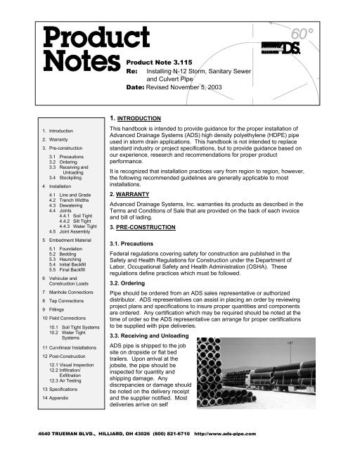
Installing N-12 Storm, Sanitary Sewer, and Culvert Pipe
Installing N-12 Storm, Sanitary Sewer, and Culvert Pipe
Installing N-12 Storm, Sanitary Sewer, and Culvert Pipe

Create successful ePaper yourself
Turn your PDF publications into a flip-book with our unique Google optimized e-Paper software.
Table 1 – Invert Adjustment for Wall Thickness<strong>Pipe</strong> Diameter in. (mm)Wall ThicknessInches feet mm<strong>12</strong>" (300 mm) 1.15" 0.10' 29 mm15" (375 mm) 1.30" 0.11" 33 mm18" (450 mm) 1.57" 0.13' 40 mm24" (525 mm) 1.86" 0.16' 47 mm30" (600 mm) 2.55" 0.21' 65 mm36" (750 mm) 2.85" 0.24' 72 mm42" (1050 mm) 3.15" 0.26' 80 mm48" (<strong>12</strong>00 mm) 3.00" 0.25' 79 mm60" (1500 mm) 3.40" 0.28' 86 mm4.2. Trench WidthsReferences for trenching practice are in AASHTOSection 30 <strong>and</strong> ASTM D2321. Both of thesespecifications provide guidelines for trench widthsapplicable to a variety of installation conditions.Trench widths may be varied based on thecompetency of the in-situ soil, backfill materials,compaction levels <strong>and</strong> loads. In general, thefollowing table provides recommended trench widthsfor most installations, to permit proper placement <strong>and</strong>compaction of backfill material in the haunches <strong>and</strong>around the pipe. However, the design engineer maymodify the trench widths based on an evaluation ofthe competency of the in-situ materials, the quality<strong>and</strong> compaction level of the backfill, the design loads<strong>and</strong> the compaction equipment to be used. In lieu ofthe engineer's recommendations or governingagency specifications, the following trench widths aresuggested.Nominal <strong>Pipe</strong> Diameter, inches(mm)Table 2 – Suggested Minimum Trench Widths<strong>Pipe</strong> OD, inches (mm)Minimum TrenchWidth, inches (mm)4" (100 mm) 4.78" (<strong>12</strong>0 mm) 21" (530 mm)6" (150 mm) 6.92" (176 mm) 23" (580 mm)8" (200 mm) 9.11" (233 mm) 25" (630 mm)10" (250 mm) 11.36" (287 mm) 28" (710 mm)<strong>12</strong>" (300 mm) 14.45" (367 mm) 31" (790 mm)15" (375 mm) 17.57" (448 mm) 34" (860 mm)18" (450 mm) 21.2" (536 mm) 39" (990 mm)24" (600 mm) 27.8" (719 mm) 48" (<strong>12</strong>20 mm)30" (750 mm) 35.1" (892 mm) 66" (1680 mm)36" (900 mm) 41.7" (1059 mm) 78" (1980 mm)42" (1050 mm) 47.7" (<strong>12</strong><strong>12</strong> mm) 83" (2110 mm)48" (<strong>12</strong>00 mm) 53.6" (1361 mm) 89" (2260 mm)60" (1500 mm) 66.3" (1684 mm) 102" (2590 mm)
Trenching should be completed in existing soils with sidewallsreasonably vertical to the top of the pipe. For positive projectionembankment installations, the embankment material should beplaced <strong>and</strong> compacted to a minimum of one (1') foot above the pipe<strong>and</strong> the trench excavated into the embankment. When excavationdepths or soil conditions require shoring or use of a trench box, thebottom of the shoring or trench box should be placed no lower thanthe top of the pipe. This prevents disruption of the backfill envelopewhen removing the shoring or trench box. If this practice cannot befollowed, consideration should be given to leaving the shoring inplace.4.3. DewateringExcessive groundwater hinders proper placement <strong>and</strong> compaction of bedding <strong>and</strong> backfill.ADS N-<strong>12</strong> pipe will float in st<strong>and</strong>ing water, therefore, it is imperative that a dry trench beprovided. It may be necessary to provide sump pumps, well points, deep wells, geofabrics,underdrains or a diversion ditch to insure a dry trench. A qualified engineer should beconsulted to determine dewatering methods.4.4. JointsADS offers a variety of joint options to satisfy specific project requirements. Threeperformance levels are commonly required for storm drain applications.4.4.1. Soil Tight JointsSoil tight joints are specified as a function of opening size,coupler length <strong>and</strong> backfill particle size. Split couplers may beused for pipe sizes up to 60" to provide a soil tight connection.The sides of the split couplers are "hinged" so they easily opento accept each end of the adjacent pipe sections. There arematching holes at the ends of the split coupler which allowsecuring the coupler with nylon ties.4.4.2. Silt Tight JointsSilt tight joints are specified where there is a high percentage of fines<strong>and</strong> groundwater potential. These joints are designed to guardagainst infiltration of soil at the joint. A bell <strong>and</strong> spigot design with anelastomeric rubber gasket meeting ASTM F-477 is generally specifiedfor silt tight applications. The ADS N-<strong>12</strong> ST IB pipe joint is designedto meet the silt tight requirements.4.4.3. Water Tight JointsWatertight joints are specified to meet a laboratorypressure test of 10.8 psi per ASTM D-32<strong>12</strong>. Thesejoints are designed to prevent infiltration of soil <strong>and</strong>exfiltration of storm water. The joints have a bell <strong>and</strong>spigot or bell–bell design <strong>and</strong> incorporate an ASTMF-477 elastomeric rubber gasket. ADS Pro-Link WT<strong>and</strong> ADS N-<strong>12</strong> WT IB pipe joints satisfy therequirements of watertight installations.
4.5. Joint AssemblySplit couplers are easily installed by laying theadjoining sections of pipe in the open splitcoupler <strong>and</strong> wrapping the coupler around thepipe. Nylon ties may then be fed through theholes in the end of the coupler to secure thecoupler to the pipe. The pipe <strong>and</strong> the inside ofthe coupler should be clean <strong>and</strong> free of dirt priorto securing the coupler.Bell <strong>and</strong> spigot or bell – bell couplers incorporating an elastomeric rubber gasket are eitheran in-line bell (N-<strong>12</strong> ST or WT IB), a welded bell (Pro-Link ST or WT) or a bell-bell (Pro-LinkWT). These couplers are easily installed by the following procedure which will insure thespecified performance:1. Thoroughly clean the bell <strong>and</strong> spigot ends,making sure they are free of mud <strong>and</strong> grit.Remove the protective shrink-wrap from thegasket. If the gasket has been removed,make sure the gasket seat is clean <strong>and</strong>reinstall the gasket by stretching it over thepipe <strong>and</strong> nesting it in the seat. Gasketsshould be installed with the marking facing thecoupler.2. Remove shipping collars (where provided)prior to lowering the pipe in the trench. Properly dispose of shipping collars outside thepipe trench. Do not install pipe with shipping collars on the pipe <strong>and</strong> do not dispose ofshipping collars in the trench.3. Lubricant is supplied for gasketed joint installation in the form of tubs. The lubricantshould be liberally applied to both the bell <strong>and</strong> spigot ends of the pipe. Care should betaken to insure lubricant is applied to the chamfered leading edge of the bell.4. Align the pipe <strong>and</strong> push the spigot home on grade. Joints should be installed with bellsfacing upstream for proper installation. Generally, pipes should be laid starting at thedownstream end <strong>and</strong> working upstream. Small diameter pipe (below 24") can usually beinstalled by pushing the joint home by h<strong>and</strong>. Larger diameters may necessitate using abar or equipment to push home. If a bar or equipment is utilized, a wood block should beused to prevent damage to the bell. When pushing the joint home, make sure beddingmaterial is not pulled into the bell by the spigot. Material such as small stones <strong>and</strong> s<strong>and</strong>pulled into the bell as the pipe is joined can cause leaks.5. EMBEDMENT MATERIALSEmbedment materials are those used for bedding, haunching <strong>and</strong> initial backfill as illustrated in Figure 1.AASHTO Section 30 <strong>and</strong> ASTM D-2321 classify soils using AASHTO <strong>and</strong> Unified soil classification,respectively. The following will describe soils using the ASTM D-2321 nomenclature with AASHTOdesignations noted.Class I – Angular crushed stone or rock, dense or open graded with little or no fines ( ¼ inch to1½ inches in size)
Class II – (GW, GP, SW, SP, GW-GC, SP-SM) Clean, coarse grained materials, such as gravel,coarse s<strong>and</strong>s <strong>and</strong> gravel/s<strong>and</strong> mixtures (1 ½ inches in size). (AASHTO classifications A1 & A3).Class III – (GM, GC, SM, SC) Coarse grained materials with fines including silty or clayey gravelsor s<strong>and</strong>s. Gravel or s<strong>and</strong> must comprise more than 50 percent of Class III materials (1½ inchesmaximum size). (AASHTO classifications A-2-4 & A-2-5).Class IV – (ML, CL, MH, CH) Fine grained materials, such as fine s<strong>and</strong> <strong>and</strong> soils containing 50percent or more clay or silt. Soils classified as Class IVa (ML or CL) have medium to lowplasticity <strong>and</strong> are not recommended in the embedment zone. Soils classified as Class IVb (MH orCH) have high plasticity <strong>and</strong> are not recommended for embedment materials.Class V – (OL, OH, PT) These materials include organic silts <strong>and</strong> clays, peat <strong>and</strong> other organicmaterials. They are not recommended for embedment materials.Note: All embedment materials should be free from lumps of frozen soil or ice when placed. Additionally,embedment materials should be placed <strong>and</strong> compacted at optimum moisture content.AASHTO SECTION 30 * ASTM D-2321 *These specifications are presented as a guide <strong>and</strong> are not a substitute for local agency/designerst<strong>and</strong>ards. Both specifications are illustrated to show similarities <strong>and</strong> ADS's recommendations arepresented in the text. Embedment materials should be specified with consideration given to design loads<strong>and</strong> the classification <strong>and</strong> suitability of native soils. For normal installations without live loads or deepcover heights, many native soils will be applicable. Also, using native soils minimizes the potential formigration of fines into the embedment material. Where native soils are not appropriate for embedmentmaterials or the loading conditions, an imported material should be considered.5.1. FoundationA stable foundation must be provided to insure proper line <strong>and</strong> grade is maintained.Unsuitable foundations must be stabilized at the engineer's direction. Unsuitable or unstablefoundations may be undercut <strong>and</strong> replaced with a suitable bedding material, placed in 6" lifts.Other methods of stabilization, such as geotextiles may be appropriate based on theengineer's judgement.
5.2. BeddingA stable <strong>and</strong> uniform bedding shall be provided for the pipe <strong>and</strong> any protruding features of itsjoints <strong>and</strong>/or fittings. The middle of the bedding equal to 1/3 of the pipe OD should be looselyplaced, with the remainder compacted to a minimum of 90 percent st<strong>and</strong>ard proctor density.Class I, II <strong>and</strong> III materials are suitable for use as bedding.5.3. HaunchingProper haunching provides a major portion of the pipe's strength <strong>and</strong> stability. Care must beexercised to insure placement <strong>and</strong> compaction of the embedment material in the haunches.For larger diameter pipes (> 30"), embedment materials should be worked under thehaunches by h<strong>and</strong>. Haunching materials may be Class I, II or III <strong>and</strong> must be placed <strong>and</strong>compacted in 8 inch maximum lifts, compacted to 90 percent st<strong>and</strong>ard proctor density.5.4. Initial BackfillInitial backfill materials are required to a minimum of ¾ of the pipediameter for proper structural performance of the pipe. TheAASHTO <strong>and</strong> ASTM specifications extend the initial backfill fromthe springline to 6 inches to <strong>12</strong> inches above the pipe to provideprotection for the pipe from construction operations duringplacement of the final backfill, <strong>and</strong> to protect the pipe from stonesor cobbles in the final backfill. For proper structural performanceof the pipe, the initial backfill need only extend to ¾ of the pipediameter. Class I, II, III or low plasticity Class IV materials may beused as initial backfill. However:Class I materials must be used in wet trenches if Class Ibedding <strong>and</strong> haunching materials are used.Class II materials must be compacted in 6 inch lifts to 90percent st<strong>and</strong>ard proctor density.Class III materials must be compacted in 6 inch lifts to 90 percent st<strong>and</strong>ard proctordensity. See note.Class IVa low plasticity materials (CL-ML) are not recommended since they must becompacted in thin lifts while at or near optimum moisture content to provide proper pipesupport. These materials may only be used under the direction of the Engineer.Class IVb high plasticity clays <strong>and</strong> silts <strong>and</strong> all Class V materials are not recommendedfor initial backfill.Note: Flooding or jetting as a procedure for compaction should only be used with theEngineer's approval <strong>and</strong> never with initial backfill material such as aggregate base orClass IV materials.Controlled Low Strength Materials (CLSM) or flowable fills are acceptable backfillmaterials. Several considerations should be accounted for when using CLSM backfill.Provisions to prevent floatation of the pipe during placement of the CLSM must be used.This can include anchoring the pipe by placing flowable fill at each joint <strong>and</strong> allowing thefill to partially cure prior to placing the flowable fill along the entire length of the pipe.Also, mechanical anchors such as bent rebar driven into competent soil or precastweights, may be used at each joint to prevent floatation. When using CLSM, the fillshould always be placed to completely encase the pipe.
5.5. Final BackfillThe final backfill should be the same material as the proposed embankment.Generally, the excavated material may be used as final backfill. Placement should be asspecified for the embankment. In lieu of a specification, the final backfill should be placed in<strong>12</strong> inch maximum lifts <strong>and</strong> compacted to a minimum 85 percent st<strong>and</strong>ard proctor density toprevent excessive settlement at the surface. Compaction should be performed at optimummoisture content.6. VEHICULAR AND CONSTRUCTION LOADSADS N-<strong>12</strong> pipes are designed to carry H-25 live loads (40,000 lbs. Axle – legal load) with <strong>12</strong> inches ofcover. This assumes a well compacted embedment <strong>and</strong> includes the subbase material for installationsunder pavement. For 60" N-<strong>12</strong> the minimum cover for H-25 loads is 2'-0".During construction, avoid heavy equipment loads (> 40,000 lbs. per axle) over the pipe. An additional <strong>12</strong>inches of temporary cover should be placed over the pipe for heavy construction load crossings.Hydrohammers or hoe-pak compactors may not be used over the pipe until at least 48 inches of coverhave been provided.7. MANHOLE CONNECTIONSConsideration should be given to the project performance specifiedwhen selecting manhole connections. When connecting to concretemanholes or inlets, grouting the pipe to the manhole or inlet using nonshrinkgrout provides a soil tight installation. A gasket placed in a pipecorrugation at the approximate center of the manhole or inlet wall willact as a water barrier. This water barrier should provide a silt tightinstallation. An ADS WaterStop Gasket can be used in a similar wayto achieve a water tight installation. Other water tight installations mayrequire flexible rubber connections such as rubber boots, "A-Loks", etc.ADS N-<strong>12</strong>/SDR- 35 adapters or the smooth exterior ADS manholeadapter pipe should be used with flexible rubber connections. Insert theADS N-<strong>12</strong>/SDR-35 or ADS manhole adapter into the flexible connectorusing a lubricant as recommended by the manufacturer of the flexibleconnector. The flexible connector should be sized to the OD of SDR-35PVC pipe. When connecting to manholes, insure backfill is placedunder the pipe adjacent to the manhole to prevent differentialsettlement.8. TAP CONNECTIONSTap connections may be accomplished using fabricated reducing fittings, saddle tees or "Insert-A-Tees".Fabricated reducing fittings are installed using normal installation procedures for the joints specified.Saddle tees are split couplers with an N-<strong>12</strong> stub welded onto the center of the coupler. A half circleapproximately 1" larger than the nominal stub diameter should be cut into each pipe end of the main line.The pipes should be aligned with the saddle tee wrapped around the pipe <strong>and</strong> secured with nylon ties."Insert-A-Tee" connections may be made at locations along the length of the pipe. Installation of an"Insert-A-Tee" should follow the manufacturer's recommendations. In general, the installation involvesmarking the location of the tap. A hole is cored using a core drill sized for the "Insert-A-Tee". Then, aneoprene boot <strong>and</strong> PVC stub are inserted in the hole <strong>and</strong> a gasketed ADS N-<strong>12</strong> pipe is inserted.9. FITTINGSADS offers a full complement of fittings. ADS st<strong>and</strong>ard fittings include tees, bends, wyes, reducers <strong>and</strong>end caps. Additionally, a full line of manifold fittings <strong>and</strong> components are available for underground storm
water management systems. All fittings are available with joints which are compatible with the pipe usedon the project, to provide a complete system. For a complete list of ADS st<strong>and</strong>ard fittings, contact yourADS representative for a fittings manual.Special fittings not included in ADS's fittings manual may be made by special order <strong>and</strong> an ADSrepresentative should be contacted for details.10. FIELD CONNECTIONSField connections may be necessary to complete pipe runs for short pipe lengths or for repairs to pipedamaged during construction. Field connections <strong>and</strong> repairs should be performed with couplerscompatible to the overall system. The following methods are applicable to both field connections <strong>and</strong>repairs. See Product Note 3.105 for more details on field cuts <strong>and</strong> connections.10.1 Soil Tight SystemsIf the damage is a hole or crack in the corrugation wall only <strong>and</strong> is less than one-quarter ofthe pipe diameter in area, <strong>and</strong> the pipe is not under pavement, clean the pipe, center a splitcoupler over the damaged area <strong>and</strong> secure snugly with nylon ties.If the damage exceeds the above criteria or if the pipe is under pavement, cut out thedamaged pipe, cut a replacement piece to fit, lay a split coupler under each exposed end,place the new pipe section in the trench <strong>and</strong> secure the coupling with nylon ties.10.2 Water Tight SystemsFor watertight systems, any damaged pipe should be removed <strong>and</strong> repaired using an ADSfield repair coupler. The vent tubes should be sealed appropriately. The pipe should be cutbeyond the damaged area <strong>and</strong> removed. A new section of pipe, cut to fit should be insertedwith a field repair coupler placed beneath each cut end of the pipe. The ends of the pipeshould be clean <strong>and</strong> free of debris. The protective film over the field coupler may then bepeeled back while adhering the coupler to the pipe. Once the coupler is in place, the tiedownb<strong>and</strong>s may be ratcheted tight to provide a watertight seal. The protective film on theoverlap seal can then be removed to complete the installation.NOTE: The above are guidelines. The final repair decision should be reviewed <strong>and</strong>determined by the project engineer.11. CURVILINEAR INSTALLATIONSADS N-<strong>12</strong> pipe can be laid on a curved alignment as a series of tangent(straight sections) deflected horizontally at each joint. However, the amountof deflection is dependent on the type of joint selected. Typically, ADS N-<strong>12</strong>ST <strong>and</strong> WT IB (in-line bell) pipe joints can only accommodate smalldeflection angles (< 1 o ) <strong>and</strong> maintain the silt-tight or water tight jointperformance for which they are designed. Split couplers will also permitsmall deflection angles (approximately 1 o to 3 o ). The ADS Pro-Link WT <strong>and</strong>ST joints (welded bells or bell-bell couplers) can accommodate deflectionangles (approximately 3 o ), however; water-tightness may be affected atlarger deflection angles. The following table may be used as a guide indetermining the radius of ADS pipe with a given joint type. The designershould contact an ADS representative before using any ADS pipe forcurvilinear installations to insure proper joint selection <strong>and</strong> performance.
Joint Type Max. D @*Limited availability.Radius (ft) per pipe length (ft)joint *10’ <strong>Pipe</strong> 13’ <strong>Pipe</strong> 20’ <strong>Pipe</strong>Diameter4"-36" Pro-link ST or WT 3 degree 197 ft 257 ft 395 ft(Welded Bells or Bell-Bell Couplers)42"-60" Pro-link ST (Welded 3 degree 197 ft 257 ft 395 ftBells or Bell-BellCouplers)4”-60” N-<strong>12</strong> ST & WT IB 1 degree X 753 ft 1159 ft<strong>12</strong>. POST –CONSTRUCTIONGenerally, no post construction is necessary for ADS pipe installations; however it is good practice toperform a visual inspection to insure proper line <strong>and</strong> grade have been achieved. It is important tounderst<strong>and</strong> that under normal conditions, any deflection will be realized within the first thirty (30) daysafter installation <strong>and</strong> generally within 2-3 days most deflection (approximately 90-95%) will be realized.This affords the inspector the opportunity to inspect the pipe shortly after installation, with the ability tonote deficiencies before the project is complete. The inspection should be performed after the pipe hasbeen laid <strong>and</strong> backfilled, but may be before final paving has been placed.The following outlines various inspection methods commonly specified for flexible pipes (plastic <strong>and</strong>metal).<strong>12</strong>.1. Visual InspectionA visual inspection will usually reveal improper line <strong>and</strong> grade as well as excessive deflection.For most projects, which specify a soil tight or silt tight joint performance, a visual inspectionis sufficient to insure a successful installation. Caution is advised when inspecting pipe orentering manhole or inlet structures to insure compliance with all OSHA regulations.<strong>12</strong>.2. Infiltration/ExfiltrationFor systems designed for watertight applications without specifying any ASTM specificationfor testing, an infiltration/exfiltration test is a simple <strong>and</strong> easy method of insuring proper jointperformance. For an infiltration/exfiltration test, a run of piping is tested by filling the systemwith water from structure to structure (manhole or inlets) <strong>and</strong> measuring the water levelimmediately after filling <strong>and</strong> at a later period of time (generally 24 hours). The drop in waterlevel can then be converted to gallons/ inch diameter/ mile /day <strong>and</strong> compared to thepermissible level established for the project. In the absence of a specified level, 200-gal/ in.dia./ mi./ day may be considered watertight. An acceptable ASTM specification for testinginfiltration/exfiltration is ASTM C969.<strong>12</strong>.3. Air TestingAfter the pipe has been laid <strong>and</strong> backfilled, each section of pipeline between manholes maybe tested by a low pressure air test. Individual joints may also be tested with appropriateequipment. This test is usually for systems where performance st<strong>and</strong>ards require watertightjoints. ASTM F-1417 may be used for air testing these systems <strong>and</strong> should be completedfrom structure to structure or for individual joints. Fabricated structures <strong>and</strong> fittings should notbe tested to avoid damaging these components.ASTM F-1417 specifies a 3.5 psi air pressure be held for a specified length of time based onthe pipe diameter with a maximum 0.5 psi pressure drop. Although the diameters listed inASTM F-1417 only include up to 36", linear interpolation for larger diameters is generallyacceptable.
13. SPECIFICATIONSThe following is a list of common material, design <strong>and</strong> performance specifications for ADS N-<strong>12</strong> pipe.This list is not all inclusive, but does include the most common applicable specifications.AASHTO M-252AASHTO M-294AASHTO Section 18AASHTO Section <strong>12</strong>AASHTO Section 30ASTM F 405ASTM F 667ASTM D 2321ASTM F 477ASTM F 1417ASTM C 969St<strong>and</strong>ard Specification for Corrugated Polyethylene Drainage TubingSt<strong>and</strong>ard Specification for Corrugated Polyethylene <strong>Pipe</strong>, 300 to 1500-mmDiameterSoil-Thermoplastic <strong>Pipe</strong> Interaction SystemsLRFD Specifications – Buried Structures <strong>and</strong> Tunnel LinersThermoplastic <strong>Pipe</strong>St<strong>and</strong>ard Specification for Corrugated Polyethylene (PE) Tubing <strong>and</strong> FittingsSt<strong>and</strong>ard Specification for Large diameter corrugated Polyethylene Tubing<strong>and</strong> FittingsSt<strong>and</strong>ard Practice for Underground Installation of Thermoplastic <strong>Pipe</strong> for<strong>Sewer</strong>s <strong>and</strong> Other Gravity-Flow ApplicationsSt<strong>and</strong>ard Specification for Elastomeric Seals (Gaskets) for Joining Plastic<strong>Pipe</strong>St<strong>and</strong>ard Test Method for Installation Acceptance of Plastic Gravity <strong>Sewer</strong>Lines Using Low-Pressure AirSt<strong>and</strong>ard Practice for Infiltration <strong>and</strong> Exfiltration Acceptance Testing ofinstalled Precast Concrete <strong>Pipe</strong> <strong>Sewer</strong> Lines14. APPENDIXThe following related documents should be consulted for additional information regarding the use of ADSN-<strong>12</strong>. These documents may be obtained from your ADS representative or by viewing our Web Site:www.ads-pipe.com.ADS Technical NotesTechnical Note 2.107 – <strong>Pipe</strong> FloatationTechnical Note 2.108 – Chemical ResistivityTechnical Note 2.109 – Flow CapacityTechnical Note 2.115 – Comparative <strong>Pipe</strong> StiffnessTechnical Note 2.116 – Abrasion ResistanceTechnical Note 2.<strong>12</strong>0 – <strong>Storm</strong> Water Detention/Retention System DesignTechnical Note 2.130 – Structural Performance of Corrugated PE <strong>Pipe</strong> using the Burns & RichardSolutionTechnical Note 2.160 – Installation of ADS N-<strong>12</strong> <strong>Pipe</strong> In Flowable FillTechnical Report 4.103 – Plastic <strong>Pipe</strong> DesignProduct NotesProduct Note 3.105 – Integral Bell TransitionProduct Note 3.106 – St<strong>and</strong>ard <strong>Pipe</strong> Perforations, N-<strong>12</strong>Product Note 3.107 – N-<strong>12</strong> Specification <strong>and</strong> Product Information