MDS NETio-TBTM Series - GE Digital Energy
MDS NETio-TBTM Series - GE Digital Energy
MDS NETio-TBTM Series - GE Digital Energy
Create successful ePaper yourself
Turn your PDF publications into a flip-book with our unique Google optimized e-Paper software.
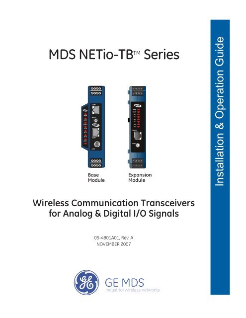
Invisible place holder<strong>MDS</strong> <strong>NETio</strong>-TB TM <strong>Series</strong>PWRLINKCOM1ETHDI-1DI-2DO-1DO-2COM2WeXPCOM1LINKBaseModuleExpansionModuleInstallation & Operation GuideWireless Communication Transceiversfor Analog & <strong>Digital</strong> I/O Signals05-4801A01, Rev. ANOVEMBER 2007
Table of Contents1 INTRODUCING THE <strong>MDS</strong> <strong>NETio</strong> SYSTEM................. 11.1 ABOUT THIS MANUAL...................................................................................................... 31.1.1 Conventions Used ...................................................................................................................31.2 PRODUCT DESCRIPTION................................................................................................ 31.3 HOW IT WORKS................................................................................................................ 51.3.1 I/O Operating Modes ...............................................................................................................51.3.2 Configuration Levels ................................................................................................................61.3.3 Module Profiles ........................................................................................................................61.4 CONNECTOR OVERVIEW................................................................................................ 71.5 DIN RAIL MOUNTING & REMOVAL................................................................................. 91.6 ACCESSORIES ...............................................................................................................102 CONFIGURING WIRELESS SYSTEMPARAMETERS.......................................................... 132.1 INTRODUCTION ............................................................................................................. 152.2 INITIAL SETUP................................................................................................................ 152.2.1 <strong>NETio</strong> Backplane Communication .........................................................................................162.2.2 Measure & Connect DC Power ..............................................................................................162.3 SET BASIC CONFIGURATION OF THE <strong>NETio</strong> BASE MODULE ................................... 172.3.1 Starting Information Screen ...................................................................................................182.3.2 Main Menu .............................................................................................................................202.3.3 Wireless Configuration Menu ................................................................................................202.3.4 TransNET Configuration ........................................................................................................212.3.5 WeXP Configuration Menu ....................................................................................................222.3.6 Wireless Expansion Module Configuration ............................................................................232.4 ASSIGNING MODULE IDs .............................................................................................. 242.4.1 ID Conflict List Menu .............................................................................................................262.4.2 Conflict (Resolution) Menu ....................................................................................................272.4.3 Configuring WeXP Wireless Expansion Modules ..................................................................272.4.4 I/O Module Configuration Menu .............................................................................................282.4.5 Module Menu .........................................................................................................................2905-4801A01, Rev. A <strong>MDS</strong> <strong>NETio</strong>-TB Installation & Operation Guide i
2.5 CHECK for NORMAL OPERATION ................................................................................. 293 I/O POINT CONFIGURATION .................................... 313.1 I/O POINT CONFIGURATION ......................................................................................... 333.2 I/O NETWORK MENU ..................................................................................................... 333.2.1 I/O Module Configuration Menu .............................................................................................343.2.2 Discrete Input Menu ..............................................................................................................353.2.3 Analog Input Menu ................................................................................................................363.2.4 Discrete Output Menu ............................................................................................................373.2.5 Analog Output Menu .............................................................................................................383.3 CONFIGURING <strong>NETio</strong> OUTPUTS for PROTOCOL CONTROL...................................... 393.4 MAPPING INPUTS TO OUTPUTS FOR SIGNAL EXTENSION & RE<strong>GE</strong>NERATION..... 393.4.1 Setting the Source Field for Mapping ....................................................................................403.5 FAILSAFE SETTINGS ..................................................................................................... 423.5.1 Configuring Failsafe Settings .................................................................................................423.5.2 Configuring Failsafe Timeout—Base Modules ......................................................................433.5.3 Configuring Failsafe Timeouts over WeXP ............................................................................433.6 I/O UPDATE REFRESH RATES ...................................................................................... 444 WIRING & TERMINATIONS ....................................... 454.1 I/O & POWER CONNECTIONS....................................................................................... 474.1.1 Module Dimensions ...............................................................................................................474.1.2 I/O Configurations .................................................................................................................474.2 I/O POINTS WIRING & TERMINATION........................................................................... 484.2.1 Analog Input Wiring (Current Signals) ...................................................................................484.2.2 Analog Output Wiring (Current Signals) ................................................................................494.2.3 Analog Input Wiring (Voltage Signals) ...................................................................................494.2.4 Discrete Points Wiring ...........................................................................................................504.2.5 Module Wiring Diagrams .......................................................................................................505 CONFIGURING THE SERIAL PORTS ....................... 595.1 Configuring the <strong>NETio</strong> Serial Port.................................................................................... 615.2 Configuring COM2 Payload Port...................................................................................... 62ii <strong>MDS</strong> <strong>NETio</strong>-TB Installation & Operation Guide 05-4801A01, Rev. A
6 PROTOCOLS .............................................................. 656.1 CONFIGURING MODBUS OPERATION......................................................................... 677 MAINTENANCE & SUPPORT FUNCTIONS ............ 697.1 INTRODUCTION ............................................................................................................. 707.2 <strong>NETio</strong> TransNET RADIO MAINTENANCE & SUPPORT................................................. 707.2.1 Performance, Statistics, RSSI Information ............................................................................707.2.2 Maintenance/Tools/Date and Time ........................................................................................717.3 WeXP & <strong>NETio</strong> MODULE MAINTENANCE ..................................................................... 727.3.1 View/Set Expansion Module WeXP RF Power ......................................................................727.3.2 Changing Base Module WeXP RF Output Power ..................................................................737.3.3 Changing WeXP RF Channel ................................................................................................747.3.4 WeXP RSSI and Backplane Communication Statistics .........................................................747.4 DEVICE, MODULE and I/O POINT DESCRIPTIONS ..................................................... 757.4.1 Changing the <strong>NETio</strong> Device Name ........................................................................................757.4.2 Changing <strong>NETio</strong> Module and I/O Point Names .....................................................................767.5 TECHNICAL SPECIFICATIONS ...................................................................................... 76General .......................................................................................................................................76<strong>NETio</strong> Base Module ....................................................................................................................77<strong>NETio</strong> Expansion Module Models...............................................................................................77Analog Input................................................................................................................................77<strong>Digital</strong> Inputs ...............................................................................................................................77Analog Outputs ...........................................................................................................................78<strong>Digital</strong> Outputs ............................................................................................................................78900 MHz Model Radio Specifications .........................................................................................782.4 GHz Model Radio Specifications ..........................................................................................78WeXP Radio Specifications - 802.15.4 .......................................................................................78Mechanical..................................................................................................................................79Agency Approvals .......................................................................................................................797.6 dBm-WATTS-VOLTS CONVERSION CHART ................................................................. 80Copyright NoticeThis publication is protected by U.S.A. copyright law. Copyright 2007, <strong>GE</strong> <strong>MDS</strong>, LLC. All rightsreserved.ISO 9001 Registration<strong>GE</strong> <strong>MDS</strong> adheres to the internationally-accepted ISO 9001 quality system standard.05-4801A01, Rev. A <strong>MDS</strong> <strong>NETio</strong>-TB Installation & Operation Guide iii
Related Materials on the InternetData sheets, frequently asked questions, application notes, information on firmware upgrades, andother valuable information can be found on the <strong>GE</strong> <strong>MDS</strong> Web site at www.<strong>GE</strong>mds.com.About <strong>GE</strong> <strong>MDS</strong>Over two decades ago, <strong>GE</strong> <strong>MDS</strong> began building radios for business-critical applications. Sincethen, we’ve installed more than 500,000 radios in over 110 countries. To succeed, we overcameimpassable terrain, brutal operating conditions and disparate, complex network configurations. Wealso became experts in wireless communication standards and system applications worldwide. Theresult of our efforts is that today, thousands of utilities around the world rely on <strong>GE</strong> <strong>MDS</strong>-basedwireless networks to manage their most critical assets.OPERATIONAL & SAFETY NOTICESFCC Transmitter IdentificationsAn <strong>MDS</strong> <strong>NETio</strong> Base Module can contain two internal FCC-approved transmitters:• FCC ID: E5<strong>MDS</strong>-EL806 “<strong>MDS</strong> OEM TransNET 900MHz FHSS transceiver”IC ID: 3738A-<strong>MDS</strong>EL806• FCC ID: OUR-XBEEPRO “2.4 GHz Zigbee module”IC ID: 4214A-XBEEPRO<strong>NETio</strong> Expansion Modules equipped with wireless expansion services (WeXP) contain one FCC-approved transmitter:• FCC ID: OUR-XBEEPRO “2.4 GHz Zigbee module”IC ID: 4214A-XBEEPRORF ExposureU.S. Installations: Professional installation required. The radio equipment described inthis guide emits radio frequency energy. Although the power level is low, the concentratedenergy from a directional antenna may pose a health hazard. For 900 MHz units, do notallow people to come closer than 23 cm (9 inches) to the antenna. For 2.4 GHz units, donot allow people to come closer than 5 cm (2 inches) to the antenna. These distances applywhether the transmitter is operated in indoor or outdoor environments.For units with the optional wireless expansion service (WeXP) installed, a minimum separationdistance of 23cm (9.05") must be maintained between the two antennas (Link andWeXP) when mounted in their final locations.More information on RF exposure is available on the Internet atwww.fcc.gov/oet/info/documents/bulletins.CSA/US NoticeThis product is available for use in Class I, Division 2, Groups A, B, C & D Hazardous Locations.Such locations are defined in Article 500 of the National Fire Protection Association (NFPA) publicationNFPA 70, otherwise known as the National Electrical Code.The transceiver has been recognized for use by the Canadian Standards Association (CSA). Thecertification for the transceiver is as a Recognized Component in hazardous locations, in accordancewith the CSA Certification STD C22.2 No. 213-M1987.iv <strong>MDS</strong> <strong>NETio</strong>-TB Installation & Operation Guide 05-4801A01, Rev. A
CSA/US Conditions of Approval:The transceiver is not acceptable as a stand-alone unit for use in the hazardous locations describedabove. It must either be mounted within another piece of equipment which is certified for hazardouslocations, or installed within guidelines, or conditions of approval, as set forth by theapproving agencies. The conditions of approval are as follows:1. The transceiver must be mounted in a separate enclosure suitable for the intended application.2. The antenna feedline, DC power cable and interface cable must be routed through conduit inaccordance with the National Electrical Code.3. Installation, operation and maintenance of the transceiver should be in accordance with thetransceiver's installation manual, and the National Electrical Code.4. Tampering or replacement with non-factory components may adversely affect the safe use ofthe transceiver in hazardous locations, and may void the approval.5. When installed in a Class I, Div. 2, Groups A, B, C or D hazardous location, observe the following:WARNING — EXPLOSION HAZARD— Do not disconnect equipment unless power hasbeen switched off or the area is known to be non-hazardous.Refer to Articles 500 through 502 of the National Electrical Code (NFPA 70) for further informationon hazardous locations and approved Division 2 wiring methods.FCC Part 15 NoticeThe transceiver complies with Part 15 of the FCC Rules. Operation is subject to the following twoconditions: (1) this device may not cause harmful interference, and (2) this device must accept anyinterference received, including interference that may cause undesired operation. This device isspecifically designed to be used under Section 15.247 of the FCC Rules and Regulations. Anyunauthorized modification or changes to this device without the express approval of MicrowaveData Systems may void the user’s authority to operate this device. Furthermore, this device isintended to be used only when installed in accordance with the instructions outlined in this manual.Failure to comply with these instructions may also void the user’s authority to operate this device.Manual Revision and AccuracyWhile every reasonable effort has been made to ensure the accuracy of this manual, productimprovements may result in minor differences between the manual and the product shipped to you.If you have additional questions or need an exact specification for a product, please contact ourCustomer Service Team using the information at the back of this guide. In addition, manualupdates can often be found on the <strong>GE</strong> <strong>MDS</strong> Web site at www.<strong>GE</strong>mds.com.Environmental InformationThe equipment that you purchased has required the extraction and use of natural resources for itsproduction. Improper disposal may contaminate the environment and present a health risk due tohazardous substances contained within. To avoid dissemination of these substances into our environment,and to diminish the demand on natural resources, we encourage you to use the appropriaterecycling systems for disposal. These systems will reuse or recycle most of the materials found inthis equipment in a sound way. Please contact <strong>GE</strong> <strong>MDS</strong> or your supplier for more information onthe proper disposal of this equipment.05-4801A01, Rev. A <strong>MDS</strong> <strong>NETio</strong>-TB Installation & Operation Guide v
vi <strong>MDS</strong> <strong>NETio</strong>-TB Installation & Operation Guide 05-4801A01, Rev. A
1INTRODUCING THE<strong>MDS</strong> <strong>NETio</strong> SYSTEM1 Chapter Counter Reset Paragraph1.1 ABOUT THIS MANUAL ........................................................... 31.1.1 Conventions Used .................................................................... 31.2 PRODUCT DESCRIPTION ..................................................... 31.3 HOW IT WORKS ..................................................................... 51.3.1 I/O Operating Modes ................................................................ 51.3.2 Configuration Levels ................................................................. 61.3.3 Module Profiles ........................................................................ 61.4 CONNECTOR OVERVIEW...................................................... 71.5 DIN RAIL MOUNTING & REMOVAL ...................................... 91.6 ACCESSORIES....................................................................... 1105-4801A01, Rev. A <strong>MDS</strong> <strong>NETio</strong>-TB Installation & Operation Guide 1
2 <strong>MDS</strong> <strong>NETio</strong>-TB Installation & Operation Guide 05-4801A01, Rev. A
1.1 ABOUT THIS MANUALThis guide provides installation and operating instructions for <strong>MDS</strong><strong>NETio</strong> <strong>Series</strong> products. It is arranged into the following chapters:• Chapter 1—Introducing the <strong>MDS</strong> <strong>NETio</strong> System (Page 3)• Chapter 2—Configuring Wireless System Parameters (Page 13)• Chapter 3—I/O Point Configuration (Page 31)• Chapter 4—Wiring and Terminations (Page 45)• Chapter 5—Serial or IP/Ethernet Configuration (Page 59)• Chapter 6—Maintenance & Support Functions (Page 69)1.1.1 Conventions UsedQuick Start Steps—How to Use Them...You will find Quick Start Step headings presented in the left-hand marginsof Chapters 2 and 3. These headings indicate essential steps for gettingthe <strong>NETio</strong> system up and running. If you only need to perform basicsetup and configuration, look for these headings and follow the instructionsgiven. The steps should be performed in sequence.Additional detail is provided for each menu screen to assist thoseneeding more information.Menu Navigation—Finding the MenuYou Need...To help show the path to a menu selection, navigation strings are usedin several places in this manual. For example, suppose you wished toaccess the I/O Module Configuration Menu. The navigation stringshown in the text would appear as follows:Main Menu>I/O Network>I/O Module ConfigurationBy following this order of menus, you will quickly reach the I/O ModuleConfiguration Menu.1.2 PRODUCT DESCRIPTION<strong>MDS</strong> <strong>NETio</strong> is an integrated, scalable family of wireless communicationproducts for analog and discrete I/O signals. It supports three primaryfunctions that can be implemented separately or concurrently:• I/O Signal Extension—This function allows acquiring, transmittingand regenerating I/O signals between control and monitoringdevices such as PLCs or RTUs.• Protocol Node—Allows direct addressing of I/O using a commercialprotocol such as MODBUS. Consult the factory for acomplete list of the protocols supported in the <strong>NETio</strong> ProtocolLibrary.• Payload Communication—Accommodates the serial connectionof a separate PLC, RTU or other peripheral device for wirelessconnectivity to host devices or systems.05-4801A01, Rev. A <strong>MDS</strong> <strong>NETio</strong>-TB Installation & Operation Guide 3
Invisible place holderExpansion Module(Optional)Base ModuleFigure 1-1. <strong>MDS</strong> <strong>NETio</strong>-TB Unit(Consisting of a Base Module & Optional Expansion Module)Basic <strong>NETio</strong>ArchitectureA <strong>NETio</strong> Unit consists of a Base Module and, if needed, one or more I/OExpansion Modules to achieve the I/O capacity required at a given location.The Base and Expansion Modules communicate with each other over aninternal power and communication bus. Optionally, Expansion Modulescan be wirelessly distributed up to 3,000 feet (914 meters) away fromthe Base Module if equipped with the WeXP option. WeXP is a completelyseparate 2.4 GHz 802.15.4 wireless network designed forshort-range communication. Actual range depends on the quality of the2.4 GHz transmission path.Figure 1-2 illustrates the “<strong>NETio</strong> Unit” concept in three differentarrangements; Base Module alone, Base Module connected with anExpansion Module, and Expansion Modules linked to the Base viaWeXP.PLC or RTU devices can optionally be connected at the Base Module’sserial port (COM2) for payload communication to host devices or systems.(Note—This does not apply with WeXP.)4 <strong>MDS</strong> <strong>NETio</strong>-TB Installation & Operation Guide 05-4801A01, Rev. A
Invisible place holder<strong>NETio</strong> Unit Concept• A <strong>NETio</strong> Unit• Always has a <strong>NETio</strong> Base Module• Optionally has one or more expansionmodules to meet users I/O count• Expansion Modules caneither connect physically toBase Module or via WeXP.• Is always a remote to a Master Radio orAccess PointWEXPUp to3,000 Feet/914 meters<strong>NETio</strong> Unit<strong>NETio</strong> Unit<strong>NETio</strong> UnitFigure 1-2. <strong>NETio</strong> “Unit Concept”1.3 HOW IT WORKS<strong>NETio</strong> reads analog and discrete input signals and generates analog anddiscrete output signals. In this guide, any analog or discrete signal isgenerically referred to as a “Point.”1.3.1 I/O Operating Modes“Signal Extender”Mode“Protocol Node”Mode<strong>NETio</strong>-TB supports two operating modes. The first is called SignalExtender mode. In this mode, an analog or discrete input point read bya <strong>NETio</strong> module at one location is transmitted to one or more <strong>NETio</strong>modules at other locations via WeXP and regenerated as an output.The second operating mode is called Protocol Node. In this mode, thedesired protocol can be selected from the <strong>NETio</strong> Protocol Library. The<strong>NETio</strong> Unit becomes “protocol aware” and you can monitor inputs andgenerate outputs using the selected protocol.Both modes can operate simultaneously. The only restriction is that<strong>NETio</strong> does not allow an output point to be generated by both protocoland signal extender modes. You must specify one or the other when configuringan output point.NOTE: <strong>NETio</strong> only supports one protocol for I/O while running inProtocol Node mode. Other protocols can be used however, forexternally-attached devices.05-4801A01, Rev. A <strong>MDS</strong> <strong>NETio</strong>-TB Installation & Operation Guide 5
1.3.2 Configuration LevelsThere are several configuration levels associated with a <strong>NETio</strong> Unitdepending upon the functionality that needs to be implemented.• <strong>NETio</strong> TransNET-class Radio Parameters• WeXP 2.4 GHz Parameters (As needed, if WeXP is used)• WeXP Network Address—Base Module and WirelessExpansion Modules.• <strong>NETio</strong> Module Activation (Required)• Unit ID—Base Module ID• Module ID—Expansion Module ID (if used)• I/O Points (Required)• I/O Point parameters such as signal type and range• Signal Extender Functions (As needed)• Protocol Node Functions (As needed)• Optional Payload Communication (As needed)• Support for an external RTU or PLC connected to <strong>NETio</strong>serial communication port.These Configuration Levels are further discussed in Chapters 2 and 3.1.3.3 Module Profiles<strong>NETio</strong> Base ModuleThe <strong>NETio</strong> Base Module operates in the license-free 902–928 MHzIndustrial, Scientific, and Medical (ISM) band. It has the following I/Ocapacity:• 1 Analog Input (AI) @ 4–20 mA, 0-5 V, 0-10 V• 1 Analog Output (AO) @ 4–20 mA• 2 Discrete Inputs (DI) @ 5–36 Vdc• 2 Discrete Outputs (DO) 36 Vdc rated at 2 A continuous load.Invisible place holderCOM2PWRWeXPLINKCOM1ETHCOM1DI-1DI-2DO-1DO-2LINKFigure 1-3. <strong>NETio</strong>-TB Base Module with WeXP Functionality6 <strong>MDS</strong> <strong>NETio</strong>-TB Installation & Operation Guide 05-4801A01, Rev. A
<strong>NETio</strong>-XMExpansion ModuleInvisible place holderMultiple <strong>NETio</strong>-XM Expansion modules can optionally attach to theBase Module if a higher I/O count is needed. No additional power orinterconnection wiring is required for Expansion Modules that are physicallyattached to the Base Module. Expansion Modules can also beequipped with WeXP 2.4 GHz functionality, which allows them to beinstalled up to 3,000 feet (914 meters) from a Base Module. There aresix Expansion Module configurations summarized in Table 1-1. ExpansionModules are available with or without WeXP capability.Table 1-1. Expansion Module Configurations(Shown with the WeXP Option present. Note that a Type 5 Module is not available.)Type 1NIOXM-1WType 2NIOXM-2WType 3NIOXM-3WType 4NIOXM-4WType 6NIOXM-6WType 7NIOXM-7WPWRPWRPWRPWRPWRPWRWeXPWeXPWeXPWeXPWeXPWeXPDI-1DI-1DO-1DI-1DI-1DI-1DI-2DI-2DO-2DI-2DI-2D0-1DO-1DI-3DO-3DI-3DO-1DO-2DO-2DI-4DO-4DI-4DO-2DO-3DI-5DO-5DI-6DO-6CONFIGCONFIGCONFIGCONFIGCONFIGCONFIGWeXPWeXPWeXPWeXPWeXPWeXP• 1 AnalogInput (0–5 V,0–10 V,4–20 mA)• 1 AnalogOutput(4–20 Ma)• 2 DiscreteInputs• 2 DiscreteOutputs• 6 DiscreteInputs• 6 DiscreteOutputs• 2 AnalogInputs(0–5 V, 0–10V, 4–20 mA)• 4 DiscreteInputs• 2 AnalogInputs—non-isolated(0–5 V)• 2 AnalogOutputs—non-isolated(0–5 V)• 2 DiscreteInputs• 2 DiscreteOutputs• 2 AnalogInputs—(4–20 mA)isolated• 1 DiscreteInputs• 3 DiscreteOutputs1.4 CONNECTOR OVERVIEWFigure 1-4 shows all of the interface connectors and LEDs present on a<strong>NETio</strong>-TB Base Module. Figure 1-5 shows this information for a<strong>NETio</strong>-XM Expansion Module. A review of these items will assist youin making the connections described later in this section.05-4801A01, Rev. A <strong>MDS</strong> <strong>NETio</strong>-TB Installation & Operation Guide 7
COM2◆ DCE Console/Terminal◆ 19,200 bps/8N1 (Default)◆ No Handshaking◆ RS/EIA-232TERMINATIONS +1–45–8LED PANEL◆ PWR —Primary Power◆ <strong>MDS</strong> entraNET Radio Link◆ COM1 —COM Port Activity◆ ETH —ETHERNET Port Activity◆ DI-1 —<strong>Digital</strong> Input 1 Active◆ DI-2 —<strong>Digital</strong> Input 2 Active◆ DO-1 —<strong>Digital</strong> Output 1 Active◆ DO-2 —<strong>Digital</strong> Output 2 ActivePWRLINKCOM1ETHDI-1DI-2DO-1DO-2TERMINATIONS9–1213–16–COM2WeXPCOM1LINK+–Invisible place holderPRIMARY POWER◆ 13.8 Vdc @ 350 mA(6–30 Vdc)◆ Negative Ground◆ 1 + / 2 –24 VDC POWER OUTPUT◆ 24.0 Vdc @ 40 mA◆ Isolated from Ground◆ Pins 3 (+) & 4 (–)WeXP RF CONNECTOR◆ Wireless Expansion◆ Antenna◆ 2.4 GHz (IEEE 802.15.4)COM1◆ DCE Console/Terminal◆ 19,200 bps/8N1 (Default)◆ No Handshaking◆ RS/EIA-232<strong>MDS</strong> entraNET RF CONNECTOR◆ 50Ω TNC connector◆ +30 dBm/1W Output (Max.)◆ –30 dBm Input (Max.)Figure 1-4. <strong>NETio</strong>-TB Base Module Interface Connectors & LEDsFigure 1-5 shows the interface connectors for a typical <strong>NETio</strong> ExpansionModule. The number and function of LEDs, as well as the presenceof the WeXP antenna connector and the 24 Vdc power output, is dependenton the model.TERMINATIONS1–45–8+–+–Invisible place holderPRIMARY POWER◆ 13.8 Vdc @ 350 mA(6–30 Vdc)◆ Negative Ground◆ 1 + / 2 –24 VDC POWER OUTPUT◆ 24.0 Vdc @ 40 mA◆ Isolated from Ground◆ Pins 3 (+) and 4 (–)PWRLED PANEL◆ Power◆ WeXP◆ <strong>Digital</strong> Input or Output ActiveWeXP RF CONNECTOR◆ Wireless Expansion◆ Antenna◆ 2.4 GHz◆ (IEEE 802.15.4)WeXPDI-1DI-2DI-3DI-4CONFIGWeXPCONFIGURATION◆ DCE Console/Terminal◆ 19,200 bps/8N1 (Default)◆ No Handshaking◆ RS/EIA-232TERMINATIONS9–1213–16Figure 1-5. Expansion Module Interface Connectors & LEDs(Typical Model Shown)Together, the <strong>NETio</strong> Base and Expansion modules offer deploymentalternatives that are uniquely scalable to a user’s I/O count, distance andlocation requirements.8 <strong>MDS</strong> <strong>NETio</strong>-TB Installation & Operation Guide 05-4801A01, Rev. A
The <strong>NETio</strong> Base Module can be purchased with two different levels ofservice:<strong>NETio</strong> Protocol Node—Supports access to the protocol libraryfor direct protocol addressability.<strong>NETio</strong> Complete—Adds concurrent payload communicationfor an attached RTU, PLC or other peripheral device, and signalextension via WeXP to protocol capabilities. Serial connectionsare supported. WeXP is also included for short-range linkage toWireless Expansion Modules installed up to 3,000 feet (914meters) away.Key OperatingFeaturesRugged PackagingRobust RadioOperationMultiple Services• Ability to read analog inputs and discrete inputs• Ability to generate analog outputs and discrete outputs• Protocol-addressable analog and discrete points via a serial connection• Analog and discrete signal regeneration between devices viaWeXP• <strong>NETio</strong> Wireless Expansion capability—WeXP• Serial communication for an external RTU or PLC<strong>MDS</strong> <strong>NETio</strong> modules are housed in compact and rugged high-impactcases that need only be protected from direct exposure to the weather.The modules are supplied with 35 mm DIN-rail brackets for quick andeasy installation.The transceivers are designed for frequency-hopping spread-spectrumoperation in the license-free 900 MHz or 2.4 GHz band. They can providereliable long distance communications over line-of-sight signalpaths. They employ digital signal processing (DSP) techniques for highperformance operation, even in the presence of weak signals or interference.Users with a mixture of equipment requiring serial data interfaces canemploy a combination of both <strong>NETio</strong> modules and <strong>MDS</strong> TransNETRemotes communicating with a common <strong>MDS</strong> TransNET MasterRadio.1.5 DIN RAIL MOUNTING & REMOVAL<strong>NETio</strong> Base and Expansion Modules are designed for direct mountingto a 35 mm DIN rail without the need for tools. To mount a module,simply hook the bracket over the top portion of the DIN rail, and thenpush the bottom of the radio in until it locks in place. Figure 1-6 showsthe <strong>NETio</strong> being attached to a DIN rail.05-4801A01, Rev. A <strong>MDS</strong> <strong>NETio</strong>-TB Installation & Operation Guide 9
Invisible place holderFigure 1-6. Mounting <strong>NETio</strong> Equipment to DIN Rail(Hook unit over top of rail, and push in at bottom)Removal from the DIN rail requires only a flat-blade screwdriver orother tool to pull down on the spring-loaded tab at the bottom of theradio’s mounting bracket (see Figure 1-7). With the tab held down,swing the bottom of the radio away from the rail, then lift the unit upslightly to fully release it from the mount.Invisible place holderFigure 1-7. Removal of <strong>NETio</strong> Equipment from DIN Rail(Pull down on tab and swing bottom of unit away from rail)1.6 ACCESSORIES<strong>MDS</strong> <strong>NETio</strong> equipment may be used with one or more of the accesso-10 <strong>MDS</strong> <strong>NETio</strong>-TB Installation & Operation Guide 05-4801A01, Rev. A
ies listed in Table 1-1. Contact the factory for ordering details.Table 1-1. AccessoriesAccessory Description <strong>MDS</strong> Part No.AC PowerAdapter KitOmni-DirectionalAntennasYagi Antenna(Directional)TNC Male-to-NFemale AdapterTNC Male-to-NFemale AdapterCableRJ-12 to DB-9Female AdapterRJ-45 to DB-9Female AdapterRJ-45 to RJ-45Straight-thruCable (CAT5)EIA-232Shielded DataCableFuseCoaxial CableAssemblyCoaxial CableAssemblyA small power supply designed for continuousservice. UL approved. Input: 120/220; Output:13.8 Vdc @ 2.5 ARugged antennas well suited for use at AccessPoint installations. Consult with your factorySales Representative for detailsRugged antennas well suited for use at Remoteinstallations. Consult with your factory SalesRepresentative for details.01-3682A02Contact factoryContact factoryOne-piece RF adaptor plug. 97-1677A161Short length of coaxial cable used to connectthe module’s TNC antenna connector to a TypeN connector commonly used on large diametercoaxial cables.Allows access to CONFIG port on ExpansionModules. Used if your configuration device isequipped with DB-9 connectors instead ofRJ-12.Allows access to COM1 on Base Modules.Used if your configuration device is equippedwith DB-9 connectors instead of RJ-45.Cable assembly used to connect an externaldevice to the transceiver. Both ends of thecable are wired identically.(Cable length ≈ 3 ft./1M)Shielded cable terminated with a DB-9 maleconnector on one end, and a DB-9 female onthe other end, 6 ft./1.8 m long.Small, board-mounted fuse used to protectagainst over-current conditions.SMA Male to N Male 50 Ohm RG-142B CoaxAssy. 12 in./30.48 cmSMA Male to N Male 50 OHM RG142B CoaxAssy. 24 in./61 cm97-1677A159(3 ft./1m)97-1677A160(6 ft./1.8m)73-2434A0273-2434A1297-1870A2097-1971A0329-1784A0397-2036A2397-2036A24Coaxial CableAssemblySMA Male to N Male 50 OHM RG142B CoaxAssy. 36 in./.91 m97-2036A25Coaxial CableAssemblySMA Female to SMA Right Angle CoaxAdapter97-2036A26Whip Antenna 2.4 GHz Antenna with SMA Male Connector 97-4278A1005-4801A01, Rev. A <strong>MDS</strong> <strong>NETio</strong>-TB Installation & Operation Guide 11
12 <strong>MDS</strong> <strong>NETio</strong>-TB Installation & Operation Guide 05-4801A01, Rev. A
2CONFIGURING WIRELESSSYSTEM PARAMETERS2 Chapter Counter Reset Paragraph2.1 INTRODUCTION 172.2 INITIAL SETUP 172.2.1 <strong>NETio</strong> Backplane Communication 182.2.2 Measure & Connect DC Power 182.3 SET BASIC CONFIGURATION OF THE <strong>NETio</strong> BASE MODULE192.3.1 Starting Information Screen 202.3.2 Main Menu 222.3.3 Wireless Configuration Menu 222.3.4 TransNET Configuration 232.3.5 WeXP Configuration Menu 242.3.6 Wireless Expansion Module Configuration 252.4 ASSIGNING MODULE IDs 262.4.1 ID Conflict List Menu 282.4.2 Conflict (Resolution) Menu 292.4.3 Configuring WeXP Wireless Expansion Modules 292.4.4 I/O Module Configuration Menu 302.4.5 Module Menu 312.5 CHECK for NORMAL OPERATION 3105-4801A01, Rev. A <strong>MDS</strong> <strong>NETio</strong>-TB Installation & Operation Guide 13
14 <strong>MDS</strong> <strong>NETio</strong>-TB Installation & Operation Guide 05-4801A01, Rev. A
2.1 INTRODUCTIONPrior to installation, it is recommended that the equipment be set up in abenchtop environment to become familiar with its operation and features.This also allows tests of various network designs and configurationsprior to installation. A benchtop test can be performed with anynumber of modules.This section describes the hardware setup and software configuration of<strong>NETio</strong>. Quick Start steps are provided to assist installers who only wishto perform basic setup and configuration tasks. Additional detail is providedfor each step, for those wishing to obtain more background. information.2.2 INITIAL SETUPThe following steps explain how to make connections to <strong>NETio</strong>, powerit up, and set basic configuration.Quick StartStep #1:Review power and module interconnection discussion below, thenproceed to Section 2.3.Figure 2-1 is a drawing of a benchtop arrangement for configuration andstaging of <strong>NETio</strong> equipment. The <strong>NETio</strong> modules may also be installedon DIN rails if desired (see “ DIN RAIL MOUNTING & REMOVAL” onPage 9).05-4801A01, Rev. A <strong>MDS</strong> <strong>NETio</strong>-TB Installation & Operation Guide 15
PWRLINKCOM1ETHDI-1DI-2DO-1DO-2ETHWeXPCOM1LINKPWRLINKCOM1ETHDI-1DI-2DO-1DO-2ETHWeXPCOM1LINKPWRWeXPDI-1DI-2DI-3DI-4CONFIGWeXPPWRWeXPDI-1DI-2DI-3DI-4CONFIGWeXPPWRWeXPDI-1DI-2DI-3DI-4CONFIGWeXPPWRWeXPDI-1DI-2DI-3DI-4CONFIGWeXPPWRWeXPDI-1DI-2DI-3DI-4CONFIGWeXPBase ModuleInvisible place holderCOM1 PortPC Running Terminal Session(19,2000 bps, 8N1)PC Running Terminal Program(19,2000 bps, 8N1)Base ModuleExp. ModuleExp. ModuleExp. ModuleExp. ModuleExp. Module(With WeXP)*COM1 PortOR:Base Module* As an alternative, WeXP-equipped Expansion Modulesmay be configured over the air via 2.4 GHz link afterthey have been configured with their WeXP NetworkAddress (See Section 2.3.7).Figure 2-1. Typical Benchtop Arrangement2.2.1 <strong>NETio</strong> Backplane CommunicationWhen a <strong>NETio</strong> Unit consists of a Base Module and Expansion Modules,as shown in Figure 2-1, all Expansion Modules should be connected tothe Base Module using the Backplane/power connector on the side ofthe modules. The configuration process is easiest if all modules areattached together via their Backplane/power connector.2.2.2 Measure & Connect DC PowerInput power applied to <strong>NETio</strong> must be within 6–30 volts DC and becapable of continuously providing a minimum of 11 Watts. (Typicalcurrent consumption is: 220 mA @13.8 Vdc for <strong>NETio</strong> Base Modules.Each module has screw terminations for power and I/O signals. Terminations1 and 2 are for power as shown in Figure 2-2. Strip the wireleads to 6 mm (0.25"). Be sure to observe proper polarity with the positivelead (+) on the left and negative on the right.16 <strong>MDS</strong> <strong>NETio</strong>-TB Installation & Operation Guide 05-4801A01, Rev. A
NOTE: When multiple modules are connected via the Backplane/powerconnector, all modules are powered via the BaseModule only. Do not connect power to each of the ExpansionModules.NOTE: It will take about 15-30 seconds for the <strong>NETio</strong> modules to beready for operation after power is connected.+–Invisible place holderPRIMARY POWER• Nominal 13.8 Vdc @ 350 mA(Range: 6–30 Vdc)• Negative Ground Only• Terminal 1 is Positive (+)• Terminal 2 is Negative (–)Figure 2-2. DC Power Input for <strong>NETio</strong> ModulesCAUTIONPOSSIBLEEQUIPMENTDAMA<strong>GE</strong>The modules must be used only with negative-groundsystems. Make sure the polarity of the power sourceis correct. The module is protected from reversepolarity by an internal diode and on-board fuse.2.3 SET BASIC CONFIGURATION OFTHE <strong>NETio</strong> BASE MODULEThe following instructions give a summary of the basic settings for a<strong>NETio</strong> Base Module.Quick StartStep #2:Console TerminalConnectionStart a HyperTerminal session to COM1 on the Base Module, and loginto <strong>NETio</strong>. Proceed to Section 2.3.1.The <strong>NETio</strong> Base Module is configured using a PC running Hyper Terminalor a console terminal (see Figure 2-3). Connect a PC to the <strong>NETio</strong>Base Module’s COM1 port and establish a HyperTerminal session usingthe following parameters: 19200 bps, 8 bits, no parity, one stop bit(8N1), flow control disabled, VT100 emulation.The COM1 port uses an RJ-45 connector. A DB-9 to RJ-45 adaptor withcable is supplied with each <strong>NETio</strong> Base Module.NOTE: The exact parameters given above must be used for consoleterminal communication. Improper settings are a commoncause of difficulty.05-4801A01, Rev. A <strong>MDS</strong> <strong>NETio</strong>-TB Installation & Operation Guide 17
PWRLINKCOM1ETHDI-1DI-2DO-1DO-2ETHWeXPCOM1LINKBase ModuleInvisible place holderCOM1 PortPC Running Terminal Session(19,2000 bps, 8N1)Figure 2-3. Local <strong>NETio</strong> Configuration SetupWith a PC connection made, log into the Base Module as follows:1. Press the ENTER key to receive the Login prompt. The COM1 LEDflashes to indicate data communications.2. At the Login prompt, enter the username (admin is the default username).Press ENTER .3. At the Password prompt, enter the password. (admin is the defaultpassword). Press ENTER . Upon successful log-in, the Starting InformationScreen appears.2.3.1 Starting Information ScreenUpon successful log-in the Starting Information Screen (Figure 2-4)appears. This screen provides a read-only overview of the BaseModule’s current operating conditions.Quick StartStep #3:Select G to go the Main Menu. Refer to Section 2.3.2, Main Menufor detailed information.18 <strong>MDS</strong> <strong>NETio</strong>-TB Installation & Operation Guide 05-4801A01, Rev. A
Invisible place holderFigure 2-4. Starting Information Screen—Local Console Session• Device Name—User-defined name for the unit (40 charactersmaximum).• Device Location—User-defined string commonly used to identifythe module’s location (40 characters maximum).• Unit—Shows the <strong>NETio</strong> Base Unit's unique Unit ID. This valuedefaults to the last four digits of the <strong>NETio</strong> Base Module’s serialnumber, but can be modified as desired.• Network Address—Shows the Network Address of the <strong>MDS</strong>TransNET network to which this Unit belongs. The NetworkAddress is essential for association to an <strong>MDS</strong> TransNET MasterRadio. All Units in a system must have the exact same NetworkAddress.• Radio Status—Shows the module’s TransNET radio associationstatus as follows:• Associated—Unit is operating normally and associated (communicating)with the TransNET Master Radio.• Alarmed—A alarming event has been logged and not cleared.Note: If an alarm is present when this screen is displayed, an“A)” will appear to the left of the Radio Status field. (The PWRLED will also flash.) Pressing A on your keyboard takes youdirectly to the Current Alarms screen.• Device Uptime—Elapsed time since the transceiver was powered-up.• Current Firmware—Version of firmware that is currently active inthe Unit.• Current User—Privilege level at which you are logged in.05-4801A01, Rev. A <strong>MDS</strong> <strong>NETio</strong>-TB Installation & Operation Guide 19
Quick StartStep #5:To configure the TransNET radio parameters, select A to go the<strong>NETio</strong> TransNET Configuration Menu (Section 2.3.4). Otherwise,proceed to Section 2.3.5.Invisible place holderFigure 2-6. Wireless Configuration Menu• TransNET Configuration—Select options for <strong>NETio</strong>TransNET-class radio parameters.• WeXP Configuration—Select options for WeXP operation (ifequipped with this feature).2.3.4 TransNET ConfigurationThe TransNET Configuration Menu allows access to all <strong>NETio</strong> TransNETradio-class parameters and provides a review of radio performancedata. The <strong>NETio</strong>-TB uses the same command line configurationfor a TransNET radio as those of a standard TransNET. Refer to the<strong>MDS</strong> TransNET manual (05-2708A01) for a complete list of commands.When finished entering commands, type ESC or clos to close theinterface.Quick StartStep #6:Complete TransNET radio configuration, then proceed to Section2.3.5.05-4801A01, Rev. A <strong>MDS</strong> <strong>NETio</strong>-TB Installation & Operation Guide 21
Invisible place holderFigure 2-8. WeXP Configuration Menu• Channel Number—The channel number can be set to any valuefrom 12 to 23.• WeXP Network Address—Unique WeXP network identifier. Werecommend using last four digits of Base Module’s serial number.• WeXP Power Level—Use space bar to select the desired RF Outputpower for WeXP radio (in dBm).• Expansion WeXP Ageout Time—Timeout period for WeXP communication.2.3.6 Wireless Expansion Module ConfigurationNOTE: Review this entire section before proceeding to Section 2.4,ASSIGNING MODULE IDs.Each Wireless Expansion Module must be configured with the uniqueWeXP Network Address used in the Base Module for wireless association(see Section 2.3.5). This can be accomplished in two ways:Method 1—Attach all wireless expansion modules to the appropriateBase Module via the Backplane/power connector. This provides accessto the Expansion Module(s) via the Base Module. Follow the remaininginstructions in this chapter for assigning module IDs. Beginning at Section2.4, you will assign the WeXP Address in Section 2.4.3.Method 2—Connect a PC to the configuration port (RJ-11 modular) onthe front of the Expansion Module and establish a HyperTerminal sessionas described in Section 2.3. This provides a command line interface.05-4801A01, Rev. A <strong>MDS</strong> <strong>NETio</strong>-TB Installation & Operation Guide 23
Quick StartStep #8:Using the command line interface, enter the following and press theReturn key:wexp netaddrRepeat this step for all Wireless Expansion Modules that are toassociate with a particular Base Module. When finished, proceed toSection 2.4.2.4 ASSIGNING MODULE IDsWhen power is applied to a <strong>NETio</strong> Base Module, an I/O Network isautomatically established for Expansion Modules. The I/O Network isone Base Module (or a Base Module plus Expansion Modules) connectedphysically via the Power/Communication Bus and/or wirelesslyvia WeXP. Note that only Wireless Expansion Modules whose WeXPNetwork Address matches the address in the Base Module (see Section2.3.5) will associate.The <strong>NETio</strong> Base Module automatically resolves the quantity, type andconnection method for Expansion Modules upon power-up and assignstemporary Module IDs until they are formally configured.Set Module IDFormally “activate” the Expansion Modules in a <strong>NETio</strong> Unit byassigning a permanent Module ID to each module.NOTE: Activation is done through the I/O Network Menu configurationscreens. Upon power-up, all <strong>NETio</strong> Module(s) will appear firstin the Unconfigured/Conflicting Module menu. Once a Module IDis assigned by the user, the Modules will appear on the I/ONetwork Menu.Figure 2-9 is an example of an operational network. If the menu displaysUNCONFIGURED/CONFLICTING MODULES, this means there are conflictsthat need to be resolved. If this menu option is not shown, then there areno conflicts and you can proceed directly to Section 2.4.3. Selecting theletter associated with a module takes you to its configuration screen.Quick StartStep #9:Select K to proceed to the Unconfigured/Conflicting Modules Menu(refer to Section 2.4.1), if shown. Otherwise, proceed to Section2.4.3, Quick Start Step 12.24 <strong>MDS</strong> <strong>NETio</strong>-TB Installation & Operation Guide 05-4801A01, Rev. A
Invisible place holderFigure 2-9. Example of I/O Network Menu• Location—Module’s “name” or description as defined by theuser. This entry is optional.• ID #—The Module ID used by this module.• Connection —The type of connection each Expansion Modulehas to the associated Base Module, for example:Base—This module is a Base Module.Wired—Connected directly to the Base Module via the Backplane/powerconnector.WeXP—Connected to the Base Module via the WeXP wirelessnetwork.• I/O Layout—The module’s I/O point (number and type) capacity.The Unconfigured and Conflicting Modules Menu is very similar to theNetwork Menu, but it lists only modules which are not configured or areimproperly configured.NOTE: In most cases, newly-installed Expansion Modules willinitially appear on the Conflicting/Unconfigured Modules list.05-4801A01, Rev. A <strong>MDS</strong> <strong>NETio</strong>-TB Installation & Operation Guide 25
Selecting the letter corresponding to a conflicting module brings you tothe Conflict Menu, Figure 2-11, where the Module ID and LocationField can be entered.2.4.2 Conflict (Resolution) MenuEach Module must be assigned a unique ID. Changing the ModuleName is optional. Once you have entered the ID, the module moves tothe I/O Network Menu.Quick StartStep #11:Select B and enter a unique Module ID. Note that Module IDs mustbe assigned to all modules in the Conflict List Menu. See Section2.4.1. Once completed, refer to Section 2.4.3.Figure 2-11. Conflict MenuUser-Alterable Parameters:• Location—Configurable name for the module.• Requested (Address) ID #—Unique Module ID number.Read-Only Parameters:• Serial #—Factory’s serial number of the module.• Connection Type—The connection method for this Expansion tothe associated Base Module. Options are: WeXP or Wired.2.4.3 Configuring WeXP Wireless ExpansionModulesOnce all module ID conflicts have been resolved, all modules willappear in the I/O Network Menu. You can change or modify the ModuleID at any time by selecting the letter associated with a particular module.The only exception is the Base Module ID, which is fixed at 0 (zero).05-4801A01, Rev. A <strong>MDS</strong> <strong>NETio</strong>-TB Installation & Operation Guide 27
The final step is to set the WeXP Network Address in any WirelessExpansion module that is part of this <strong>NETio</strong> Unit. Note that the WeXPNetwork Address must match the value set in the Base Module inChapter 2.Quick StartStep #12:If WeXP is used, configure the WeXP Network Address, if notalready configured in Section 2.3.6 Method 2. Otherwise, proceed toSection 2.5 for final checkout.NOTE: Wireless Expansion Modules show a “Connection” type of“wired” if they are temporarily attached via the Backplane/powerconnector. They will display “WeXP” oncethe WeXP Network Address is configured and the moduleis unattached.Select the letter for the Wireless Expansion Module that you wish toconfigure. Proceed to Section 2.4.4.Figure 2-12. Example of I/O Network Menu2.4.4 I/O Module Configuration MenuThe I/O Module Configuration Menu (Figure 2-13) is where all <strong>NETio</strong>Module parameters can be set or viewed, including I/O point parameters.Quick StartStep #13:Select A and go to the Module Menu (proceed to Section 2.4.5)28 <strong>MDS</strong> <strong>NETio</strong>-TB Installation & Operation Guide 05-4801A01, Rev. A
Invisible place holderFigure 2-13. I/O Module Configuration Menu2.4.5 Module MenuThe Module Menu (Figure 2-14) is where general <strong>NETio</strong> moduleparameters can be viewed or set.Quick StartStep #14:Select B and enter the WeXP Network Address to match theaddress entered in the Base Module (see Section 2.3.5 above). Next,proceed to Section 2.5.Invisible place holderFigure 2-14. Module Menu2.5 CHECK for NORMAL OPERATIONWhen all modules have been configured, you should be able to use allmodules in the I/O Network Menu. Note that you will only see Wireless05-4801A01, Rev. A <strong>MDS</strong> <strong>NETio</strong>-TB Installation & Operation Guide 29
Expansion Modules displayed with a connection type of WeXP if theynot attached via the Backplane/power connector.Figure 2-15. Example of I/O Network MenuObserve the Base Module LEDs on the faceplate for the proper indications.In a normally operating system, the following LED indicationsshould be seen:• PWR—Lit continuously• LINK—Lit continuously (if associated with an TransNET AP)• COM1—Blinks to indicate data communications with terminalIn a normally operating system, the following LED indications shouldbe seen within 30 seconds of start-up on the Wireless ExpansionModule:• PWR—Lit continuously• WeXP—Lit continuouslyIf the previous steps have been successfully completed, the I/O pointconfiguration can be set. These steps are described in CHAPTER-3 I/OPOINT CONFIGURATION beginning on Page 31.30 <strong>MDS</strong> <strong>NETio</strong>-TB Installation & Operation Guide 05-4801A01, Rev. A
3I/O POINTCONFIGURATIONter 3 .............................................................................................. Counter ResetChap-3.1 I/O POINT CONFIGURATION353.2 I/O NETWORK MENU353.2.1 I/O Module Configuration Menu 363.2.2 Discrete Input Menu 373.2.3 Analog Input Menu 383.2.4 Discrete Output Menu 393.2.5 Analog Output Menu 403.3 CONFIGURING <strong>NETio</strong> OUTPUTS for PROTOCOL CONTROL413.4 MAPPING INPUTS TO OUTPUTS FOR SIGNAL EXTENSIONAND RE<strong>GE</strong>NERATION413.4.1 Setting the Source Field for Mapping 423.5 FAILSAFE SETTINGS443.5.1 Configuring Failsafe Settings 443.5.2 Configuring Failsafe Timeout—Base Modules 453.5.3 Configuring Failsafe Timeouts over WeXP 453.6 I/O UPDATE REFRESH RATES4605-4801A01, Rev. A <strong>MDS</strong> <strong>NETio</strong>-TB Installation & Operation Guide 31
32 <strong>MDS</strong> <strong>NETio</strong>-TB Installation & Operation Guide 05-4801A01, Rev. A
3.1 I/O POINT CONFIGURATIONThis section describes how to configure I/O points in a <strong>NETio</strong> Unit. Thisprocess is required for each I/O signal connected to a <strong>NETio</strong> Unit. Theinstructions here assume that you have established a PC connection withthe unit as described earlier in this manual.This section also gives instructions for “mapping” an input to a particularoutput. This is required in cases where an input signal connected toone <strong>NETio</strong> Module must be regenerated as an output from a different<strong>NETio</strong> Module.Each I/O point has a unique address that corresponds to where it islocated in a <strong>NETio</strong> Unit. You use this address when mapping one pointto another in a Signal Extender function, or when selecting the point ina Protocol node.A point address consists of three fields:• Module ID—The number assigned to the <strong>NETio</strong> module.For Expansion Modules: The Module ID is set by the user (seeASSIGNING MODULE IDs on Page 24).• Point Number—This number references the physical terminationnumber of a particular I/O point on a <strong>NETio</strong> Module. It isautomatically assigned.Each I/O point connected to a <strong>NETio</strong> Unit has an address with theformat shown below. Each field is separated by a comma:,3.2 I/O NETWORK MENUThe I/O Network menu shows the Base Module and any ExpansionModules (if present) connected via the Backplane/power connector orWeXP. If there are a large number of modules in the network, it will benecessary to scroll down the screen to view all entries.I/O points are configured by selecting the module that a signal is wiredto and then selecting a particular I/O point. When a wireless expansionmodule is selected the WeXP LED blinks to indicate that it is beingaccessed for configuration.Quick StartStep #15:Select the letter associated with the module containing the I/O pointto be configured. Proceed to Section 3.2.1.05-4801A01, Rev. A <strong>MDS</strong> <strong>NETio</strong>-TB Installation & Operation Guide 33
Figure 3-1. Example of I/O Network Menu3.2.1 I/O Module Configuration MenuThe I/O Module Configuration Menu is where all <strong>NETio</strong> Module-specificinformation can be viewed or changed.Invisible place holderFigure 3-2. I/O Module Configuration Menu34 <strong>MDS</strong> <strong>NETio</strong>-TB Installation & Operation Guide 05-4801A01, Rev. A
Quick StartStep #16:Select the letter associated with a specific I/O point to be configuredand proceed as follows:If a Discrete Input is selected, proceed to Section 3.2.2.If a Discrete Output is selected, proceed to Section 3.2.4If an Analog Input is selected, proceed to Section 3.2.3If an Analog Output is selected, proceed to Section 3.2.53.2.2 Discrete Input MenuThis menu allows you to view and change the Point ID Tag for a discreteinput by selecting the letter A.Figure 3-3. Discrete Input Menu• Point ID Tag—Text to describe the use of this I/O point.• Value—The current state of this point.• Point Address— A composite of the Unit ID, Module ID andPoint (address) Number. The values are separated by commas.05-4801A01, Rev. A <strong>MDS</strong> <strong>NETio</strong>-TB Installation & Operation Guide 35
3.2.3 Analog Input MenuThis menu allows you to view and change the Input Range and/or thePoint ID Tag for an analog input.Invisible place holderThis menuallowsyou to review and revise many parameters for a analog point.Figure 3-4. Analog Input MenuUser-Alterable Parameters:• Point ID Tag—Text to describe the use of this I/O point.• Range Mode—User-configured field that sets the type ofinput. Options are determined by module type but can be4-20 mA, 0-5 volts, or 0-10 volts.Read-Only Parameters:• Value—The present value in A/D counts for this pointaddress.• Point Address—Address used to identify this input point. Formatis: Unit ID, Module ID, Point Number36 <strong>MDS</strong> <strong>NETio</strong>-TB Installation & Operation Guide 05-4801A01, Rev. A
3.2.4 Discrete Output MenuThis menu allows you to view and change various parameters for a discreteoutput point.Figure 3-5. Discrete Output MenuUser-Alterable Parameters:• Point ID Tag—Text to describe the use of this I/O point.• Source—The input point address to get this output's valuefrom. Format is: Module ID, Point Number (see Section3.4).• Force Mode—A convenience field that allows the user to forcean output value. Press the spacebar to cycle through the availablesettings as follows:Off—Force Mode disabled.High (1)—Force Mode enabled and output is turned on.Low (0)—Force Mode enabled and output is turned off.• Failsafe Mode—The way this output should fail if communicationsis lost. Press the spacebar to cycle through the optionsas follows:On—On or logic 1.Off—Off or logic 0.Last—Hold last value• Failsafe Timeout—Amount of time (in ms) that the communicationlink with a Source Point must be lost before enteringFailsafe Mode.Read-Only Parameters:• Point Address—Address used to identify this input point. Formatis: [Module ID, Point Number]• Value—The current state (logic high or logic low) of thispoint.05-4801A01, Rev. A <strong>MDS</strong> <strong>NETio</strong>-TB Installation & Operation Guide 37
3.2.5 Analog Output MenuThis menu allows you to review and revise many parameters for aanalog output point.Figure 3-6. Analog Output MenuUser-Alterable Parameters:• Point ID Tag—Text to describe the use of this I/O point.• Range Mode—User-configured field that sets the type ofinput. Options are determined by module type but can be4-20 mA, 0-5 volts, or 0-10 volts.• Source—The input point address to get this output's valuefrom. Format is: Module ID, Point Number (see Section3.4).• Failsafe Mode—The way this output should fail if communicationsis lost. Press the spacebar to cycle through the optionsas follows:High—Highest possible output for range.Low—Lowest possible output for range.Last—Last valuePreset—User specified value.• Preset Value—Preset value for Failsafe operation.• Force Mode—A convenience field that allows the user to forcean output value. Press the spacebar to cycle through the availablesettings.Off—Force Mode disabled.38 <strong>MDS</strong> <strong>NETio</strong>-TB Installation & Operation Guide 05-4801A01, Rev. A
High (1)—Force Mode enabled and output is turned on.Low (0)—Force Mode enabled and output is turned off.• Force Value—The value (in counts) to output when in ForceMode.• Failsafe Timeout—Amount of time (in ms) that the communicationlink with a Source Point must be lost before enteringFailsafe Mode.Read-Only Parameters:• Point Address—Address used to identify this input point. Formatis: Module ID, Point Number• Value—The present value in A/D counts for this pointaddress.3.3 CONFIGURING <strong>NETio</strong> OUTPUTSfor PROTOCOL CONTROLIn order for a protocol to set control outputs for either analog or discreteoutputs connected to <strong>NETio</strong> Modules, the Source variable for the particularoutput must be set to Protocol. To do this, Select the letter for the“Source” variable (shown in Figure 3-5 or Figure 3-6) to view the menushown in Figure 3-7. Enter p to enable protocol control as the source forthe output.Invisible place holderFigure 3-7. I/O Mapping Wizard3.4 MAPPING INPUTS TO OUTPUTSFOR SIGNAL EXTENSION ANDRE<strong>GE</strong>NERATIONOne of the primary uses of <strong>NETio</strong> is to regenerate Input signals connectedto <strong>NETio</strong> modules at one location as outputs from <strong>NETio</strong> modulesat a different location. This is accomplished by mapping.05-4801A01, Rev. A <strong>MDS</strong> <strong>NETio</strong>-TB Installation & Operation Guide 39
Figure 3-8 shows a simplified representation of mapping. A 4-20 mAanalog input is connected to the <strong>NETio</strong> Wireless Expansion Module (onthe left) with a Module ID of 0. This input is mapped to a 4-20 mAanalog output connected to the <strong>NETio</strong> Expansion Module with aModule ID of 1(on the right).To configure the mapping, enter the address of the Analog Input (in thisexample, 0, AI 1) in the Source field for the Analog Output (in thisexample, 1, AO 1).Invisible place holderFigure 3-8. I/O Mapping OverviewI/O signals can be mapped between <strong>NETio</strong> Modules that share the sameWeXP Network Address and/or <strong>NETio</strong>-TB Base Module. The only limitationis than an input can only map to an output of the same type(analog-to-analog and discrete-to-discrete).3.4.1 Setting the Source Field for MappingMapping is accomplished simply by setting the address of the inputpoint signal into the source field in an output point.Figure 3-9 shows the Analog Output Menu with the source field set to 3,AI 1. This means that this Analog Output will regenerate the signal connectedto AI 1 in Module ID 3.40 <strong>MDS</strong> <strong>NETio</strong>-TB Installation & Operation Guide 05-4801A01, Rev. A
Invisible place holderFigure 3-9. Analog Output MenuFigure 3-10 shows a simple representation of a <strong>NETio</strong> Unit that usesWeXP.Invisible place holderFigure 3-10. I/O Mapping Concept with WeXPTo map an Analog Input connected to Module ID 2 to the Analog Outputon the Base Module, follow these steps:1. Go to the Analog Output Menu for Analog Output # 1 on the BaseModule (see Figure 3-9), and select C to enter the source address.2. <strong>NETio</strong> prompts you for three entries as follows:a. The Module ID of the Source Signal. (In this example, the ModuleID is 2.)b. The Point number of the Source Signal. In this example, it isAI 1 for Analog Input #1.05-4801A01, Rev. A <strong>MDS</strong> <strong>NETio</strong>-TB Installation & Operation Guide 41
Note that pressing the spacebar will cycle through two AIchoices for Analog and six DI choices for Discretes. This is dueto the maximum capacity for Analog inputs and Discrete inputson any <strong>NETio</strong> Module.3.5 FAILSAFE SETTINGS<strong>NETio</strong> Failsafe settings allow configuration of the output signal’sbehavior in the event of loss of communication. By definition, anyoutput signal a <strong>NETio</strong> module has been configured to generate relies onone or more of these communication modes:1. WeXP—Wireless communication between Wireless ExpansionModules and a <strong>NETio</strong> Base Module within a <strong>NETio</strong> Unit.2. <strong>NETio</strong> Backplane—Wired communication between a Base Moduleand Expansion Modules using the <strong>NETio</strong> Backplane/power Connectors.When any one or more of these communication modes fails for a configurableperiod of time, an output will enter Failsafe mode and generatethe Failsafe value selected by the user. The user can accept the factorysettings or modify them, but Failsafe behavior is always activated for anoutput signal.3.5.1 Configuring Failsafe SettingsFigure 3-11 shows the Analog Output menu with a field for FailsafeMode.Invisible place holderFigure 3-11. Analog Output MenuFor an Analog Output the Failsafe Mode options are:HIGH—Set output to the highest value in the range.LOW—Set output to the lowest value in the range.LAST—Holds last value output prior to communication failure.42 <strong>MDS</strong> <strong>NETio</strong>-TB Installation & Operation Guide 05-4801A01, Rev. A
PRESET—Generate a preset value. When this option is selected,a variable field is presented where you can enter the preset value.For a Discrete Output the Failsafe Mode options are:HIGH—Output is set to logic 1.Continued...LOW—Output is set to logic 0.LAST—Output last state prior to communication failure.3.5.2 Configuring Failsafe Timeout—Base ModulesFigure 3-11 also shows a read-only field for Failsafe/WeXP Timeout. Thisfield defines the timeout period in milliseconds (ms). The Failsafe Timeoutis dictated by the WeXP timeout described in Configuring FailsafeTimeouts over WeXP below.3.5.3 Configuring Failsafe Timeouts over WeXPThe WeXP Failsafe Timeout values are set in a <strong>NETio</strong> Base Module andin the appropriate Wireless Expansion Module. They may be changed inthe Base Module by selecting C for the WeXP Configuration Menushown in Figure 3-12 (Main Menu>Wireless Configuration>WeXP Configuration).Invisible place holderFigure 3-12. WeXP Configuration MenuThe default value is 5000 ms (5 seconds) The value should not be setbelow 1000 ms (1 second).The WeXP Timeout value is set in Wireless Expansion Modules byselecting the Expansion Module from the I/O Network Menu thenselecting A for Configure Module. The Module Menu shown inFigure 3-13 is displayed.05-4801A01, Rev. A <strong>MDS</strong> <strong>NETio</strong>-TB Installation & Operation Guide 43
Invisible place holderFigure 3-13. Module MenuThe default WeXP timeout setting may be changed by selecting F fromthe menu. The default setting is 5000 ms (5 seconds). This value shouldnot be set lower than 1000 ms (1 second).3.6 I/O UPDATE REFRESH RATESWhen <strong>NETio</strong> Modules are configured to map input signals to outputs, itis important to know how fast the output signal is being refreshed.I/O that is mapped between Wireless Expansion Modules and a BaseModule via WeXP is updated at approximately 100 ms per module.Consequently, if there is one Wireless Expansion Module associatedwith a Base Module, then all I/O will update at the following rates:• (# of Wireless Expansion Modules x 100 ms)• ([1] Wireless Expansion Module x 100 = 100 ms)If there are four Wireless Expansion Modules associated with a BaseModule, the refresh rate for any one I/O point would be as follows:• 4 Wireless Expansion Modules x 100 = 400 ms44 <strong>MDS</strong> <strong>NETio</strong>-TB Installation & Operation Guide 05-4801A01, Rev. A
4WIRING & TERMINATIONS4 Chapter Counter Reset4.1 I/O & POWER CONNECTIONS ........................................... 674.1.1 Module Dimensions ............................................................... 674.1.2 I/O Configurations ................................................................. 674.2 I/O POINTS WIRING & TERMINATION................................ 684.2.1 Analog Input Wiring (Current Signals) ................................... 684.2.2 Analog Output Wiring (Current Signals) ................................ 694.2.3 Analog Input Wiring (Voltage Signals) ................................... 694.2.4 Discrete Points Wiring ........................................................... 704.2.5 Module Wiring Diagrams ....................................................... 7005-4801A01, Rev. A <strong>MDS</strong> <strong>NETio</strong>-TB Installation & Operation Guide 45
46 <strong>MDS</strong> <strong>NETio</strong>-TB Installation & Operation Guide 05-4801A01, Rev. A
4.1 I/O & POWER CONNECTIONSThis section explains how to connect the <strong>NETio</strong> modules to externalinterface equipment and make DC power connections. All connectionsto external devices are made at the screw terminals at the front cornersof each module.A label on the side of each enclosure shows the basic terminal descriptionsfor the module, I/O capacity and module type.Invisible place holderTerminations01–0405–08COM2PWRWeXPPWRLINKCOM1WeXPDI-1DI-2DI-3DI-4ETHDI-1CONFIGDI-2DO-1DO-2COM1LINKWeXPFigure 4-1. I/O Point Terminations(Termination assignments are dependent on module type)4.1.1 Module DimensionsDimensions for the Base and Expansion Modules are provided below:Base Module Dimensions14.6 H x 4.14 W x 11.4 D cm (5.75 H x 1.63 W x 4.5 D in.)Expansion Module Dimensions (all types)14.6 H x 3.00 W* x 11.4 D cm (5.75 H x 1.18 W* x 4.5 D in.)* Width does not include 3 mm (0.12 in.) projection for connector andmating pegs.4.1.2 I/O Configurations09–1213–16<strong>NETio</strong> modules are available in a variety of configurations dependingon the requirements of the particular application. Table 4-1 lists theavailable module types and shows the functions supported by each type.05-4801A01, Rev. A <strong>MDS</strong> <strong>NETio</strong>-TB Installation & Operation Guide 47
In addition, references are also given to show where detailed wiringinformation may be found in this manual.Table 4-1. I/O ConfigurationsModule Model I/O Type Functions Supported I/O Wiring Examples& TerminationsBase<strong>NETio</strong>NETIO-TB N/A 2DI, 2DO, 1AI, 1AO Figure 4-8 on Page 51Table 4-3 on Page 52Expansion<strong>NETio</strong>-XMNIOXM-1 1 2DI, 2DO, 1AI, 1AO Figure 4-9 on Page 52Table 4-3 on Page 52NIOXM-2 2 6DI Figure 4-10 on Page 53Table 4-4 on Page 53NIOXM-3 3 6DO Figure 4-11 on Page 54Table 4-5 on Page 54NIOXM-4 4 4DI, 2AI Figure 4-12 on Page 55Table 4-6 on Page 55NIOXM-6 6 2AI, 2AO, 2DI, 2DO Figure 4-9 on Page 52Table 4-3 on Page 52NIOXM-7 7 2AI, 1DI, 3DO Table 4-8 on Page 574.2 I/O POINTS WIRING &TERMINATIONThis section provides two views of wiring schemes for the <strong>NETio</strong> modules.The first is a simplified view with block diagrams organized bytype of I/O application. The second view is specific, with connectionsshown based on actual module types. These drawings do not reflect allpossible wiring schemes or applications. Please contact <strong>MDS</strong> TechnicalServices if additional guidance is required.4.2.1 Analog Input Wiring (Current Signals)2-Wire Transmitterw/External Power SupplyPOWERSUPPLYTRANSMITTERAIAI<strong>MDS</strong> <strong>NETio</strong>Base orExpansion2-Wire Transmitterw/<strong>NETio</strong> Power SupplyTRANSMITTER24 ISO24 ISOAI <strong>MDS</strong> <strong>NETio</strong>Base orAI ExpansionFigure 4-2. 2-Wire Transmitter Wiring48 <strong>MDS</strong> <strong>NETio</strong>-TB Installation & Operation Guide 05-4801A01, Rev. A
Invisible place holder3-Wire Transmitterw/External Power SupplyPOWERSUPPLYTRANSMITTERSignalAIAI<strong>MDS</strong> <strong>NETio</strong>Base orExpansion3-Wire Transmitterw/<strong>NETio</strong> Power SupplyTRANSMITTERSignal24 ISO24 ISOAI <strong>MDS</strong> <strong>NETio</strong>Base orAI ExpansionFigure 4-3. 3-Wire Transmitter WiringInvisible place holder4-Wire Transmitterw/External Power SupplyPOWERSUPPLYTRANSMITTERSupply SignalAIAI<strong>MDS</strong> <strong>NETio</strong>Base orExpansion4-Wire Transmitterw/<strong>NETio</strong> Power SupplyTRANSMITTERSupplySupplySignalSignal24 ISO24 ISOAI<strong>MDS</strong> <strong>NETio</strong>Base orAIExpansionFigure 4-4. 4-Wire Transmitter Wiring4.2.2 Analog Output Wiring (Current Signals)Analog Current Modew/External Power Supply<strong>MDS</strong> <strong>NETio</strong>Base orExpansionAOAOLOADPOWERSUPPLYAnalog Current Modew/<strong>NETio</strong> Power Supply24 ISO24 ISO<strong>MDS</strong> <strong>NETio</strong>AOBase orExpansionAOLOADFigure 4-5. 2-Wire Analog Current Mode Wiring4.2.3 Analog Input Wiring (Voltage Signals)Analog InputVoltage ModeVOLTA<strong>GE</strong>SOURCEAIAI<strong>MDS</strong> <strong>NETio</strong>Base orExpansionFigure 4-6. 2-Wire Analog Voltage Mode Wiring05-4801A01, Rev. A <strong>MDS</strong> <strong>NETio</strong>-TB Installation & Operation Guide 49
4.2.4 Discrete Points WiringSWITCHDiscrete Inputw/External Power SupplyPOWERSUPPLYDIDI<strong>MDS</strong> <strong>NETio</strong>Base orExpansionDiscrete Outputw/External Power Supply<strong>MDS</strong> <strong>NETio</strong>Base orExpansionDODOLOADPOWERSUPPLYFigure 4-7. 2-Wire Discrete Wiring4.2.5 Module Wiring DiagramsThe following diagrams are based on specific applications of <strong>NETio</strong>Modules.50 <strong>MDS</strong> <strong>NETio</strong>-TB Installation & Operation Guide 05-4801A01, Rev. A
Invisible place holderFigure 4-8. <strong>NETio</strong>-TB Base Module I/O WiringTable 4-2. <strong>NETio</strong>-TB Base Module I/O TerminationsFunctions: 2DI, 2DO, 1AI, 1AOTERM FUNCTION TERM FUNCTION TERM FUNCTION TERM FUNCTION01 POWER + 05 Ain + 09 Dout 1 + 13 Din 1 +02 POWER – 06 Ain – 10 Dout 1 – 14 Din 1 –03 24 ISO + 07 Aout + 11 Dout 2 + 15 Din 2 +04 24 ISO – 08 Aout – 12 Dout 2 – 16 Din 2 –05-4801A01, Rev. A <strong>MDS</strong> <strong>NETio</strong>-TB Installation & Operation Guide 51
Invisible place holderFigure 4-9. <strong>NETio</strong>-XM-1 Expansion Module I/O WiringTable 4-3. <strong>NETio</strong>-XM-1 Expansion Module I/O TerminationsFunctions: 2DI, 2DO, 1AI, 1AOTERM FUNCTION TERM FUNCTION TERM FUNCTION TERM FUNCTION01 POWER + 05 Ain + 09 Dout 1 + 13 Din 1 +02 POWER – 06 Ain – 10 Dout 1 – 14 Din 1 –03 24 ISO + 07 Aout + 11 Dout 2 + 15 Din 2 +04 24 ISO – 08 Aout – 12 Dout 2 – 16 Din 2 –52 <strong>MDS</strong> <strong>NETio</strong>-TB Installation & Operation Guide 05-4801A01, Rev. A
Figure 4-10. <strong>NETio</strong>-XM-2 Expansion Module I/O WiringTable 4-4. <strong>NETio</strong>-XM-2 I/O Configuration 2 Terminations,Functions: 6DITERM FUNCTION TERM FUNCTION TERM FUNCTION TERM FUNCTION01 POWER + 05 Din 1 + 09 Din 3 + 13 Din 5 +02 POWER – 06 Din 1 – 10 Din 3 – 14 Din 5 –03 24 ISO + 07 Din 2 + 11 Din 4 + 15 Din 6 +04 24 ISO – 08 Din 2 – 12 Din 4 – 16 Din 6 –05-4801A01, Rev. A <strong>MDS</strong> <strong>NETio</strong>-TB Installation & Operation Guide 53
POWER IN6–30 VdcInvisible place holderTERMINALS01–0405–08PWRWeXPDO-1DO-2DO-3DO-4DO-5DO-6CONFIGDiscrete Outputw/External Power SupplyWeXPDoutDout09–1213–16TERMINALSLOADPOWERSUPPLYFigure 4-11. <strong>NETio</strong>-XM-3 Expansion Module I/O WiringTable 4-5. <strong>NETio</strong>-XM-3 I/O Configuration 3,Terminal Functions: 6DOTERM FUNCTION TERM FUNCTION TERM FUNCTION TERM FUNCTION01 POWER + 05 Dout 1 + 09 Dout 3 + 13 Dout 5 +02 POWER – 06 Dout 1 – 10 Dout 3 – 14 Dout 5 –03 24 ISO + 07 Dout 2 + 11 Dout 4 + 15 Dout 6 +04 24 ISO – 08 Dout 2 – 12 Dout 4 – 16 Dout 6 –54 <strong>MDS</strong> <strong>NETio</strong>-TB Installation & Operation Guide 05-4801A01, Rev. A
POWER IN6–30 VdcInvisible place holder24V24VTERMINALS01–04POWERSUPPLYTRANSMITTERSIGAinAin05–08AinAinTRANSMITTERAnalog Input: Current or Voltage2-Wire Transmitterw/External Power SupplyPWRWeXPDI-1DI-2DI-3DI-4Analog Input: Currentw/<strong>NETio</strong>-Supplied PowerCONFIGWeXPDiscrete Inputw/External Power SupplyPOWERSUPPLYSWITCHDinDin09–1213–16TERMINALSFigure 4-12. <strong>NETio</strong>-XM-4 Expansion Module I/O WiringTable 4-6. <strong>NETio</strong>-XM-4 I/O Configuration 4,Terminal Functions: 4DI, 2AITERM FUNCTION TERM FUNCTION TERM FUNCTION TERM FUNCTION01 POWER + 05 Ain 1 + 08 Din 1 + 13 Din 3 +02 POWER – 06 Ain 1 – 10 Din 1 – 14 Din 3 –03 24 ISO + 07 Ain 2 + 11 Din 2 + 15 Din 4 +04 24 ISO – 08 Ain 2 – 12 Din 2 – 16 Din 4 –NOTE: There is no Type 5 Module offered for the <strong>NETio</strong> product line.05-4801A01, Rev. A <strong>MDS</strong> <strong>NETio</strong>-TB Installation & Operation Guide 55
Invisible place holderFigure 4-13. <strong>NETio</strong>-XM-6 Expansion Module I/O WiringTable 4-7. <strong>NETio</strong>-XM-6 Expansion Module I/O TerminationsFunctions: 2DI, 2DO, 2AI (V), 2A0 (V)Note: Analog inputs and outputs are not isolatedTERM FUNCTION TERM FUNCTION TERM FUNCTION TERM FUNCTION01 POWER + 05 Aout 1 09 Dout 1 + 13 Din 1 +02 POWER – 06 Aout 2 10 Dout 1 – 14 Din 1 –03 GROUND 07 Ain 1 11 Dout 2 + 15 Din 2 +04 GROUND 08 Ain 2 12 Dout 2 – 16 Din 2 –56 <strong>MDS</strong> <strong>NETio</strong>-TB Installation & Operation Guide 05-4801A01, Rev. A
For wiring information on Type 7 Modules, refer to Table 4-8 below,and the following sections in this manual:• Section 4.2.1, Analog Input Wiring (Current Signals) for connectinganalog inputs.• Section 4.2.4, Discrete Points Wiring for connecting discreteinput or output pointsTable 4-8. <strong>NETio</strong>-XM-7 Expansion Module I/O TerminationsFunctions: 1DI, 3DO, 2AI (I)TERM FUNCTION TERM FUNCTION TERM FUNCTION TERM FUNCTION01 POWER + 05 Ain 1 + 09 Dout 1 + 13 Din 1 +02 POWER – 06 Ain 1 – 10 Dout 1 – 14 Din 1 –03 GROUND 07 Ain 2 + 11 Dout 2 + 15 Dout 3 +04 GROUND 08 Ain 2 – 12 Dout 2 – 16 Dout 3 –05-4801A01, Rev. A <strong>MDS</strong> <strong>NETio</strong>-TB Installation & Operation Guide 57
58 <strong>MDS</strong> <strong>NETio</strong>-TB Installation & Operation Guide 05-4801A01, Rev. A
5CONFIGURING THESERIAL PORTS5 Chapter Counter Reset Serial Port .................................... 815.1.1 Configuring the <strong>NETio</strong> Serial Port ......................................... 815.1.2 Configuring the IP Ethernet Port ........................................... 835.2 Configuring COM2 Payload Port..................................................XX05-4801A01, Rev. A <strong>MDS</strong> <strong>NETio</strong>-TB Installation & Operation Guide 59
60 <strong>MDS</strong> <strong>NETio</strong>-TB Installation & Operation Guide 05-4801A01, Rev. A
5.1 Configuring the <strong>NETio</strong> Serial PortTo configure the <strong>NETio</strong> Serial Port (COM1), select D from the <strong>NETio</strong>Main Menu shown in Figure 5-1.Invisible place holderFigure 5-1. Main MenuThe COM1 Configuration Menu will be presented as shown inFigure 5-2 below.Invisible place holderFigure 5-2. COM1 Configuration Menu• Baud Rate—This menu item is used to set the data rate for theCOM1 port in bits-per-second. [1,200–115,200; 19200]• Format—This item allows the user to set the interface signalingparameters that will be used. Baud Rate (see above entryfor allowable range), Data bits, parity and stop bits may beset using this command. [7N1, 7E2, 7N2, 7O2, 7E1, 7O1, 8N1, 8N2,8E1, 8E2, 8O1, 8O2; 8N1]05-4801A01, Rev. A <strong>MDS</strong> <strong>NETio</strong>-TB Installation & Operation Guide 61
5.2 Configuring COM2 Payload PortThe <strong>NETio</strong> COM2 port is used for connecting a serial device (such as aPLC or RTU) for payload communication to a host system via a TransNETMaster radio.To configure the COM2 port, select item G from the Main Menu (seeFigure 5-1). The Payload/Configuration Menu is presented as shown inFigure 5-3.Invisible place holderFigure 5-3. Payload/Protocol Configuration MenuFrom the Payload/Protocol Configuration Menu, select item A to configureCOM2 and the TB Payload Configuration Menu is presented asshown in Figure 5-4.Invisible place holderFigure 5-4. TB Payload Configuration Menu62 <strong>MDS</strong> <strong>NETio</strong>-TB Installation & Operation Guide 05-4801A01, Rev. A
Current Mode—Shows the mode the COM2 port is currently in. Use thespacebar to toggle between Transparent Data Mode and Protocol LocalMaster Mode.InterGap Byte Count—Sets the number of bytes times that signify the endof a message.NOTE: Setting Protocol Local Master tells <strong>NETio</strong> to process amessage locally. It will not be transmitted over the air.05-4801A01, Rev. A <strong>MDS</strong> <strong>NETio</strong>-TB Installation & Operation Guide 63
64 <strong>MDS</strong> <strong>NETio</strong>-TB Installation & Operation Guide 05-4801A01, Rev. A
6 PROTOCOLS6 Chapter Counter Reset Paragraph6.1 CONFIGURING MODBUS OPERATION.............................. 8705-4801A01, Rev. A <strong>MDS</strong> <strong>NETio</strong>-TB Installation & Operation Guide 65
66 <strong>MDS</strong> <strong>NETio</strong>-TB Installation & Operation Guide 05-4801A01, Rev. A
6.1 CONFIGURING MODBUSOPERATIONA <strong>NETio</strong> Base Module will process MODBUS messages that comefrom one of two sources depending upon how the user has configured it.These sources are:Over the air from an TransNET Master radio—This method allows a<strong>NETio</strong> Base Module to wirelessly communicate with a MODBUSMaster device or system via the TransNET Master radio. The MODBUSMaster device is physically connected to the TransNET Master radio.From a local source—This method allows a <strong>NETio</strong> Base Module tocommunicate with a MODBUS Master device or system physically connectedto the COM2 serial port on the <strong>NETio</strong> Base Module.NOTE: For detailed instructions about addressing <strong>NETio</strong> includingthe MODBUS Memory Map and the MODBUS functionssupported, please download the MODBUS Protocoladdendum from the <strong>GE</strong> <strong>MDS</strong> website.From the <strong>NETio</strong> Main Menu (Figure 6-1) select item G, Payload/ProtocolConfiguration.Invisible place holderFigure 6-1. Main Menu3. In the Payload/Protocol Configuration Menu shown in Figure 6-2 selectitem B) MODBUS.05-4801A01, Rev. A <strong>MDS</strong> <strong>NETio</strong>-TB Installation & Operation Guide 67
Invisible place holderFigure 6-2. Protocol Configuration Menu(selection pending)4. In the MODBUS Protocol Menu (Figure 6-3), select A) to enter theMODBUS Slave Address. Next, select B) to enable the MODBUSprotocol.Invisible place holderFigure 6-3. Modbus Protocol Menu68 <strong>MDS</strong> <strong>NETio</strong>-TB Installation & Operation Guide 05-4801A01, Rev. A
7 MAINTENANCE &SUPPORT FUNCTIONS7 Chapter Counter Reset Paragraph7.1 INTRODUCTION ....................................................................... 947.2 <strong>NETio</strong> TransNET RADIO MAINTENANCE & SUPPORT........... 947.2.1 Modifying <strong>NETio</strong> TransNET RF Output Power ............................947.2.2 Performance, Statistics, RSSI Information ..................................957.2.3 Setting Encryption Approved Access Points and Passwords ......967.2.4 Maintenance/Tools/Date and Time ..............................................977.3 WeXP & <strong>NETio</strong> MODULE MAINTENANCE............................... 977.3.1 View/Set Expansion Module WeXP RF Power ............................987.3.2 Changing Base Module WeXP RF Output Power .......................987.3.3 Changing WeXP RF Channel ......................................................997.3.4 WeXP RSSI and Backplane Communication Statistics ...............997.4 DEVICE, MODULE and I/O POINT DESCRIPTIONS ............. 1017.4.1 Changing the <strong>NETio</strong> Device Name ...........................................1017.4.2 Changing <strong>NETio</strong> Module and I/O Point Names .........................1027.5 TECHNICAL SPECIFICATIONS.............................................. 102General...........................................................................................102<strong>NETio</strong> Base module........................................................................102<strong>NETio</strong> Expansion module models ..................................................103Analog Input ...................................................................................103<strong>Digital</strong> Inputs...................................................................................103Analog Outputs...............................................................................103<strong>Digital</strong> Outputs ................................................................................103900 MHz Model Radio specifications .............................................1042.4 GHz Model Radio specifications...............................................104WeXP radio specifications - 802.15.4.............................................104Mechanical .....................................................................................104Agency Approvals...........................................................................1047.6 dBm-WATTS-VOLTS CONVERSION CHART ......................... 10605-4801A01, Rev. A <strong>MDS</strong> <strong>NETio</strong>-TB Installation & Operation Guide 69
7.1 INTRODUCTIONThis chapter describes the various menus available for the maintenance,support and customization of <strong>NETio</strong>. The chapter is divided into the followingmajor sections:• <strong>NETio</strong> TransNET Radio Information• WeXP Radio Information (useful if <strong>NETio</strong> is equipped withWeXP functionality)• <strong>NETio</strong> Device and I/O Module customization7.2 <strong>NETio</strong> TransNET RADIOMAINTENANCE & SUPPORTAll <strong>NETio</strong> TransNET related configuration, maintenance and supportinformation is accessed through the <strong>NETio</strong> Main Menu shown inFigure 7-1.Invisible place holderFigure 7-1. <strong>NETio</strong> Main Menu7.2.1 Performance, Statistics, RSSI Information<strong>NETio</strong> Performance information and statistics are available from thePerformance Statistics Menu. (Figure 7-2) is shown. All communicationstatistics can be reached from this menu. To reach this menu, selectStatistics/Events>Performance Statistics.70 <strong>MDS</strong> <strong>NETio</strong>-TB Installation & Operation Guide 05-4801A01, Rev. A
Invisible place holderFigure 7-2. Performance Statistics MenuTo review TransNET radio information, select TransNET Radio Statistics.The menu shown in Figure 7-3 is presented.Invisible place holderFigure 7-3. TransNET Radio Statistics Menu7.2.2 Maintenance/Tools/Date and TimeThe Maintenance/Tools Menu (Main Menu>Maintenance/Tools) shown inFigure 7-4. It contains various selections for:• Version—Shows the firmware versions and which image is running.• Verify—Verifies the integrity of the firmware in the radio.• Reboot—Restarts <strong>NETio</strong> firmware.• Current Time—Shows the <strong>NETio</strong>’s date and time.05-4801A01, Rev. A <strong>MDS</strong> <strong>NETio</strong>-TB Installation & Operation Guide 71
Invisible place holderFigure 7-4. Maintenance/Tools Menu7.3 WeXP & <strong>NETio</strong> MODULEMAINTENANCEMost of the user-settable parameters for WeXP and Expansion Modulesare covered in earlier chapters of this guide. The few remaining parametersare accessed from the I/O Module Configuration Menu shown inFigure 7-5 (Main Menu>I/O Network>I/O Module Configuration).Invisible place holderFigure 7-5. I/O Module Configuration Menu7.3.1 View/Set Expansion Module WeXP RF PowerThe Module Menu (Main Menu>I/O Network>I/O Module Configuration>ConfigureModule) allows viewing or changing the WeXP’s RF output powerlevel. Figure 7-6 shows this menu.72 <strong>MDS</strong> <strong>NETio</strong>-TB Installation & Operation Guide 05-4801A01, Rev. A
To change the power level, select WeXP Power Level and use the spacebarto cycle through the available output power settings.Invisible place holderFigure 7-6. Module Menu7.3.2 Changing Base Module WeXP RF OutputPowerThe WeXP output power for a Base Module is configured from theWeXP Configuration Menu shown in Figure 7-7 (Main Menu>WirelessConfiguration>WeXP Configuration).Select WeXP Power Level and use the spacebar to cycle through the availablesettings.Invisible place holderFigure 7-7. WeXP Configuration Menu05-4801A01, Rev. A <strong>MDS</strong> <strong>NETio</strong>-TB Installation & Operation Guide 73
7.3.3 Changing WeXP RF ChannelThe WeXP RF channel for a Base Module is set using the WeXP ConfigurationMenu shown in Figure 7-7 (Main Menu>Wireless Configuration>WeXPConfiguration). To change the channel, select Channel Numberand enter any number between 12 and 23.7.3.4 WeXP RSSI and Backplane CommunicationStatisticsThe communications performance for WeXP and the <strong>NETio</strong> Backplanecan be viewed via the I/O Module Configuration Menu (Figure 7-5 onPage 72). To view the performance, select Module Performance/Statisticsfrom this menu. If this selection is made from a Base Module then themenu shown in Figure 7-8 is displayed. If the selection is made from aWireless Expansion Module then the menu shown in Figure 7-9appears.Invisible place holderFigure 7-8. I/O Module Statistics Menu74 <strong>MDS</strong> <strong>NETio</strong>-TB Installation & Operation Guide 05-4801A01, Rev. A
Invisible place holderFigure 7-9. I/O Module Statistics MenuSelecting Expansion WeXP Performance presents the screen shown inFigure 7-10.Invisible place holderFigure 7-10. Expansion WeXP Performance Menu7.4 DEVICE, MODULE and I/O POINTDESCRIPTIONS<strong>NETio</strong> allows users the ability to customize the names for a <strong>NETio</strong> Unit,Module and I/O Point. This is useful when the user wants to identifydevices or I/O Points by their location, type of service, or signal ID.7.4.1 Changing the <strong>NETio</strong> Device NameThe Owner, Device Name and Device Location can be modified in theDevice Menu shown in Figure 7-11 (Main Menu>Device).05-4801A01, Rev. A <strong>MDS</strong> <strong>NETio</strong>-TB Installation & Operation Guide 75
Invisible place holderFigure 7-11. Device Menu7.4.2 Changing <strong>NETio</strong> Module and I/O Point Names<strong>NETio</strong> Module Names are changed by selecting Location at the ModuleMenu shown in Figure 7-6 on Page 73.I/O Point Names are changed by selecting Point ID Tag in the I/O PointMenus, an example of which is shown in Figure 7-12.Invisible place holderFigure 7-12. Example of Point ID Tag Selection(This example shows Discrete Input Menu)7.5 TECHNICAL SPECIFICATIONSGeneral• Power: 6-30 Vdc76 <strong>MDS</strong> <strong>NETio</strong>-TB Installation & Operation Guide 05-4801A01, Rev. A
• Current Draw• Transmit: less than 600 mA (@13.8V)• Receive: less than 100 mA (@13.8V)• Sleep Mode: 10mA at 12 Vdc less than 1mA at 12 Vdc inShutdown Mode• Temperature: -40 to +70 degrees C<strong>NETio</strong> Base Module• <strong>NETio</strong>-TB:• I/O Capacity: 1 AI, 1 AO, 2 DI, 2 DO+ AI Type: Configurable as 4-20mA, 0-5 Vdc, 0-10 Vdc+ AO Type: 4-20 mA• Supports serial communication• Compatible with <strong>MDS</strong> TransNET Masters• Supports I/O Signal Extender functions or over WeXP towireless expansion modules• Two serial RJ45 connectors, one separate device<strong>NETio</strong> Expansion Module Models• <strong>NETio</strong>-XM1 capacity: 1 AI, 1 AO, 2 DI, 2 DO• AI Type: Configurable as 4-20mA, 0-5 Vdc, 0-10 Vdc• AO Type: 4-20mA• <strong>NETio</strong>-XM2 capacity: 6 DI• <strong>NETio</strong>-XM3 capacity: 6 DO• <strong>NETio</strong>-XM4 capacity: 2 AI, 4 DI• AI Type: Configurable as 4-20mA, 0-5 Vdc, 0-10 Vdc• <strong>NETio</strong>-XM6 capacity: 2 AI, 2 AO, 2 DI, 2 DO• AI Type: 0-5 Vdc• AO Type: 0-5 Vdc• <strong>NETio</strong>-XM7 capacity: 2 AI, 1 DI, 3 DO• AI Type: 4-20mAAnalog Input• Optionally power 4-20 mA loop.• Accuracy• Current: ± 12.2 uA• Voltage: ± 6.1 mV• A/D Resolution: 22 bit• Isolation: 1400 V input to power• Note that inputs on XM6 are not isolated<strong>Digital</strong> Inputs• Type: 5-36 Vdc with pulse counting• Isolation: 3000 V to chassis ground05-4801A01, Rev. A <strong>MDS</strong> <strong>NETio</strong>-TB Installation & Operation Guide 77
Analog Outputs• Accuracy• Current: ± 32 uA• Isolation: 1400 V output to power• D/A Resolution: 16 bits<strong>Digital</strong> Outputs• Capacity: 36 Vdc• FET Relay• Load Current: 2A continuous per output• Isolation: 3700 V to chassis ground900 MHz Model Radio Specifications• Data Rate: 106 Kbps over-the-air• Frequency Band: 902-928 MHz ISM band• Spreading Mode: Frequency Hopping Spread Spectrum• Range 1 :• Typical Fixed Range: 25 miles• Maximum Fixed Range: 60 miles• System Gain: 136 dB• Carrier Power: 0.1 to 1 watt (20 to 30 dBm)• Receiver Sensitivity: -106 dBm (1 x 10⁻⁶ BER) typicalWeXP Radio Specifications - 802.15.4• Frequency Band: 2.4 GHz to 2.4835 GHz• Modulation: OQPSK• Range: 3,000 feet (914 meters) typical; longer ranges with LOS• Carrier Power: 60 mW (18 dBm)• System Gain: 27 dBm• Receiver Sensitivity: -100 dBm (1% packet error rate)Mechanical• Case: High impact plastic• DIN Rail Mounting• Dimensions (Base Module): 14.6 H x 4.14 W x 11.4 D cm. (5.75H x 1.63 W x 4.5 D in.)• Dimensions (Expansion Module): 14.6 H x 3.00 W x 11.4 Dcm (5.75 H x 1.18 W* x 4.5 D in.)• Weight: 226 g (.5 lb.)Agency Approvals• FCC Part 15.247• IC - Industry Canada - RSS210• CSA Class 1 Div. 2 Groups A, B, C and D for hazardous locations(ANSI/UL equivalent) 278 <strong>MDS</strong> <strong>NETio</strong>-TB Installation & Operation Guide 05-4801A01, Rev. A
1. Typical fixed range calculation assumes a 6 dBd gainOmni-directional antenna on a 100 ft. tower at the AP, a 10 dBd gainYagi antenna on a 25 ft. mast at the Remote, with output powerdecreased to yield maximum allowable EIRP (36 dBm), a 10 dBfade margin, and a mix of agricultural and commercial terrain withline-of-sight transmission path.2. The transceiver is not acceptable as a stand-alone unit for use in thehazardous locations described above. It must either be mountedwithin another piece of equipment, which is certified for hazardouslocations, or installed within guidelines, or conditions of approval,as set forth by the approving agencies.05-4801A01, Rev. A <strong>MDS</strong> <strong>NETio</strong>-TB Installation & Operation Guide 79
7.6 dBm-WATTS-VOLTS CONVERSIONCHARTTable 7-1 is provided as a convenience for determining the equivalentvoltage or wattage of an RF power expressed in dBm.Table 7-1. dBm-Watts-Volts Conversion—for 50 ohm systemsdBm V Po+53 100.0 200W+50 70.7 100W+49 64.0 80W+48 58.0 64W+47 50.0 50W+46 44.5 40W+45 40.0 32W+44 32.5 25W+43 32.0 20W+42 28.0 16W+41 26.2 12.5W+40 22.5 10W+39 20.0 8W+38 18.0 6.4W+37 16.0 5W+36 14.1 4W+35 12.5 3.2W+34 11.5 2.5W+33 10.0 2W+32 9.0 1.6W+31 8.0 1.25W+30 7.10 1.0W+29 6.40 800mW+28 5.80 640mW+27 5.00 500mW+26 4.45 400mW+25 4.00 320mW+24 3.55 250mW+23 3.20 200mW+22 2.80 160mW+21 2.52 125mW+20 2.25 100mW+19 2.00 80mW+18 1.80 64mW+17 1.60 50mW+16 1.41 40mW+15 1.25 32mW+14 1.15 25mW+13 1.00 20mW+12 .90 16mW+11 .80 12.5mW+10 .71 10mW+9 .64 8mW+8 .58 6.4mW+7 .500 5mW+6 .445 4mW+5 .400 3.2mW+4 .355 2.5mW+3 .320 2.0mW+2 .280 1.6mW+1 .252 1.25mWdBm V Po0 .225 1.0mW-1 .200 .80mW-2 .180 .64mW-3 .160 .50mW-4 .141 .40mW-5 .125 .32mW-6 .115 .25mW-7 .100 .20mW-8 .090 .16mW-9 .080 .125mW-10 .071 .10mW-11 .064-12 .058-13 .050-14 .045-15 .040-16 .0355dBm mV Po-17 31.5-18 28.5-19 25.1-20 22.5 .01mW-21 20.0-22 17.9-23 15.9-24 14.1-25 12.8-26 11.5-27 10.0-28 8.9-29 8.0-30 7.1 .001mW-31 6.25-32 5.8-33 5.0-34 4.5-35 4.0-36 3.5-37 3.2-38 2.85-39 2.5-40 2.25 .1μW-41 2.0-42 1.8-43 1.6-44 1.4-45 1.25-46 1.18-47 1.00-48 0.90dBm mV Po-49 0.80-50 0.71 .01μW-51 0.64-52 0.57-53 0.50-54 0.45-55 0.40-56 0.351-57 0.32-58 0.286-59 0.251-60 0.225 .001μW-61 0.200-62 0.180-63 0.160-64 0.141dBm μV Po-65 128-66 115-67 100-68 90-69 80-70 71 .1nW-71 65-72 58-73 50-74 45-75 40-76 35-77 32-78 29-79 25-80 22.5 .01nW-81 20.0-82 18.0-83 16.0-84 11.1-85 12.9-86 11.5-87 10.0-88 9.0-89 8.0-90 7.1 .001nW-91 6.1-92 5.75-93 5.0-94 4.5-95 4.0-96 3.51-97 3.2dBm μV Po-98 2.9-99 2.51-100 2.25 .1pW-101 2.0-102 1.8-103 1.6-104 1.41-105 1.27-106 1.18dBm nV Po-107 1000-108 900-109 800-110 710 .01pW-111 640-112 580-113 500-114 450-115 400-116 355-117 325-118 285-119 251-120 225 .001pW-121 200-122 180-123 160-124 141-125 128-126 117-127 100-128 90-129 80 .1ƒW-130 71-131 61-132 58-133 50-134 45-135 40-136 35-137 33-138 29-139 25-140 23 .01ƒW80 <strong>MDS</strong> <strong>NETio</strong>-TB Installation & Operation Guide 05-4801A01, Rev. A
IN CASE OF DIFFICULTY...<strong>GE</strong> <strong>MDS</strong> products are designed for long life and trouble-free operation. However, this equipment, as withall electronic equipment, may have an occasional component failure. The following information will assistyou in the event that servicing becomes necessary.TECHNICAL ASSISTANCETechnical assistance for <strong>GE</strong> <strong>MDS</strong> products is available from our Technical Support Department duringbusiness hours (8:00 A.M.—5:30 P.M. Eastern Time). When calling, please give the complete model numberof the radio, along with a description of the trouble/symptom(s) that you are experiencing. In many cases,problems can be resolved over the telephone, without the need for returning the unit to the factory. Pleaseuse one of the following means for product assistance:Phone: 585 241-5510 E-Mail: TechSupport@<strong>GE</strong>mds.comFAX: 585 242-8369 Web: www.<strong>GE</strong>mds.comFACTORY SERVICEComponent level repair of this equipment is not recommended in the field. Many components are installedusing surface mount technology, which requires specialized training and equipment for proper servicing.For this reason, the equipment should be returned to the factory for any PC board repairs. The factory is bestequipped to diagnose, repair and align your radio to its proper operating specifications.If return of the equipment is necessary, you must obtain a Service Request Order (SRO) number. Thisnumber helps expedite the repair so that the equipment can be repaired and returned to you as quickly aspossible. Please be sure to include the SRO number on the outside of the shipping box, and on any correspondencerelating to the repair. No equipment will be accepted for repair without an SRO number.SRO numbers are issued online at www.<strong>GE</strong>mds.com/support/product/sro/. Your number will be issuedimmediately after the required information is entered. Please be sure to have the model number(s), serialnumber(s), detailed reason for return, "ship to" address, "bill to" address, and contact name, phone number,and fax number available when requesting an SRO number. A purchase order number or pre-payment willbe required for any units that are out of warranty, or for product conversion.If you prefer, you may contact our Product Services department to obtain an SRO number:Phone Number: 585-241-5540Fax Number: 585-242-8400E-mail Address: productservices@<strong>GE</strong>mds.comThe radio must be properly packed for return to the factory. The original shipping container and packagingmaterials should be used whenever possible. All factory returns should be addressed to:<strong>GE</strong> <strong>MDS</strong>, LLCProduct Services Department(SRO No. XXXX)175 Science ParkwayRochester, NY 14620 USAWhen repairs have been completed, the equipment will be returned to you by the same shipping methodused to send it to the factory. Please specify if you wish to make different shipping arrangements. To inquireabout an in-process repair, you may contact our Product Services Group using the telephone, Fax, or E-mailinformation given above.
<strong>GE</strong> <strong>MDS</strong>, LLC175 Science ParkwayRochester, NY 14620General Business: +1 585 242-9600FAX: +1 585 242-9620Web: www.<strong>GE</strong>mds.com


