TelTone-TLS3B-UM c19981109 - ElectronicsAndBooks
TelTone-TLS3B-UM c19981109 - ElectronicsAndBooks
TelTone-TLS3B-UM c19981109 - ElectronicsAndBooks
- No tags were found...
You also want an ePaper? Increase the reach of your titles
YUMPU automatically turns print PDFs into web optimized ePapers that Google loves.
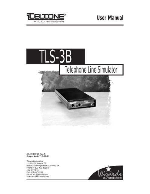
User ManualTLS-3BTelephone Line Simulator40-400-00032, Rev. ACovers Model TLS-3B-01Teltone Corporation22121-20th Avenue SEBothell, Washington 98021-4408 USAPhone: 1-800-426-3926 or425-487-1515Fax: 425-487-2288E-mail: info@teltone.comWebsite: www.teltone.com
This page intentionally left blank.
ContentsIntroduction ..........................................................................31. Connectors and Lights .....................................................42. How to Install the TLS-3B.................................................53. How to Operate the TLS-3B .............................................64. Caller ID ...........................................................................85. Programming the TLS-3B...............................................106. Programming Command Summary ................................147. Specifications .................................................................168. Warranty and Service .....................................................1840-400-00032, Rev. A 1
Regulatory Compliance:This equipment has been tested and found to comply with the limits for aClass A digital device, pursuant to part 15 of the FCC Rules. These limits aredesigned to provide reasonable protection against harmful interference whenthe equipment is operated in a commercial environment. This equipmentgenerates, uses and can radiate radio frequency energy and, if not installedand used in accordance with the instruction manual, may cause harmfulinterference in which case the user will be required to correct the interferenceat his own expense.Copyright © 1995 Teltone Corporation. Teltone is a registered trademark of Teltone Corporation.Teltone Corporation22121-20th Avenue SEBothell, WA 98021-4408Phone: 425-487-1515Fax: 425-487-22882 40-400-00032, Rev. A
TLS-3BIntroductionThe Teltone TLS-3B is a portable, two-line device that emulates thepublic telephone network. The TLS-3B is a tool for demonstrating telephoneinstruments and other telecommunications equipment such as faxmachines and modems. The TLS-3B’s small size and light weight make itideal for trade shows and other sales presentations, and for testingtelephone sets, key systems, and PBX installations.Like the public telephone network but on a smaller scale, the TLS-3B canprovide dial tone, audible ring and busy signals to the telephone or otherdevice connected to it. When a caller uses one phone or other device todial up the second phone, the TLS-3B sends ringing current to thesecond phone until it goes off-hook. The TLS-3B then establishes aconnection between the two phones. Either telephone can then initiate adisconnect sequence by going on-hook.Many of the TLS-3B’s features are programmable, including telephonenumbers, off-hook modes, signal delays, test tone frequencies and lineattentuation. The TLS-3B also provides Caller Identification information toboth lines, and lights a Visual Message Waiting indicator.In other words, the TLS-3B is a simple telephone network in a box. Whena telephone connection is not available, or when installing a temporarytelephone line would be costly, the TLS-3B provides all the signals andfunctions you will need to demonstrate or test your telephones, modems,and other telecommunications equipment.40-400-00032, Rev. A 3
1. TLS-3B Connectors and LightsThe front panel of the TLS-3B has two telephone line jacks, with a greenstatus indicator light for each line, and a green Power indicator light. Thepower input connector is on the rear panel.Status LightsWhen a telephone (or other device) connected to one of the Line connectorsis off hook, the corresponding Line indicator lights. The Line lightdims (not totally dark) when the TLS-3B decodes valid DTMF from theoff-hook device. If the off-hook device sends rotary dialing signals, theline indicator will flicker on and off during dialing.When the TLS-3B sends a ringing signal to a telephone attached to oneof the Line connectors, the corresponding Line indicator flickers on andoff rapidly.The green Power indicator alternates between full and half brightness(blink) when the TLS-3B is operating. (Single blink = Setup 1, doubleblink = Setup 2. See Section 5 for more information.) If the Power indicatoris dark, no power is connected to the TLS-3B. If it lights, but does notflicker, the TLS-3B’s internal processor is not working properly.Line JacksTwo Line connectors (RJ-11 modular telephone jacks) are located on thefront panel. These connectors mate with the plugs on standard modulartelephone cords.Power ConnectorThe power connector requires a 24-volt DC power source. A 120-VAC24-volt DC power pack is supplied with the TLS-3B. Do not use the TLS-3B with a power pack that supplies a different voltage. Use only with aClass 2 power supply!Figure 1TLS-3B Front and Rear Panels4 40-400-00032, Rev. A
2. How to Install the TLS-3BThe TLS-3B works with analog loop start telephone sets only. It will notwork with ground start, proprietary, or digital phone sets.Follow these steps to install the TLS-3B:1. Plug the connector at the end of the power pack cable into the connectoron the rear panel of the TLS-3B.2. Plug the power pack into a 120-volt AC wall outlet. The POWERindicator will light.3. Use a modular telephone cable to connect the telephones (or otherdevices such as modems or fax machines) to the Line 1 and Line 2connectors of the TLS-3B.4. Lift the handset of the telephone connected to Line 1. The Line 1indicator should light. Hang up and do the same thing for Line 2.Figure 2 shows a typical installation.WARNING: Do not try to connect the TLS-3B to the public telephonenetwork. Incoming ringing signals use voltages that can damage internalcomponents in the TLS-3B.WARNING: The TLS-3B generates a 100-volt ringing signal. Keep yourhands away from the plugs at the end of modular cables plugged into theTLS-3B when the other line is off hook.Installing a Call IdentifierIn order to use the TLS-3B’s Caller ID feature, you must use an externalcall identifier, or a telephone set with Caller ID built in. In most cases, thecall identifier goes between the TLS-3B and the telephone set, but followthe instructions supplied with the call identifier. When the call identifiermanual tells you to plug a cable into a wall outlet, connect it to the TLS-3B.Figure 2Typical TLS-3B Installation40-400-00032, Rev. A 5
3. How to Operate the TLS-3BThe TLS-3B has one talk path between the two lines. When a telephoneconnected to either line goes off-hook while the other is still on-hook, theoff-hook telephone receives dial tone. If a telephone is already off-hook,the second telephone will not receive dial tone (silence).The TLS-3B stores two separate configurations, called Setup 1 andSetup 2. This enables two different users to store settings they use often(for example, the sales staff might use the TLS-3B in one setup, andengineering the other). In Setup 1, the Power LED blinks once; in Setup 2it blinks twice. See Section 5 for more information.Each line has two programmable telephone numbers. Section 5 of theUser’s Guide contains instructions for setting the telephone numbers. Tocall the other telephone, lift the handset and dial one of the numbersassigned to the telephone you want to call. The TLS-3B recognizes bothrotary (pulse) and tone dialing.The default telephone numbers for the two lines are:Line 1 = 101 and 201 Line 2 = 102 and 202To call Line 2:(Primary) Dial 102(Secondary) Dial 202One long ring, repeated until answer2 seconds on, 4 seconds offTwo short rings (programmable)(800 mS on, 400 mS off, 800 mS on,4 seconds offTo call Line 1:(Primary) Dial 101(Secondary) Dial 201One long ring, repeated until answer2 seconds on, 4 seconds offTwo short rings (programmable)(800 mS on, 400 mS off, 800 mS on,4 seconds offWhen the other telephone rings, lift the handset to answer. The twotelephones are now connected. To break the connection, hang up eithertelephone.The Caller ID transmission sends the primary telephone number of thecaller’s line.6 40-400-00032, Rev. A
Calling Party SupervisionThe U.S. telephone network typically uses Calling Party Supervision,meaning that even though the called party hangs up, he may be reconnectedto the calling party when the phone is taken off-hook again. Thecalling party must hang up for the called party to be fully disconnectedbefore initiating a new call. The telephone network will timeout anddisconnect the call within 5-20 seconds, giving the called party dial tonewhen he goes off-hook again.The TLS-3B also provides Calling Party Answer Supervision. If the calledparty goes on-hook and comes off-hook again before the forced disconnector disconnect tone is sent, the call will be reestablished. However, ifthe calling party goes on-hook and then goes back off-hook again afterthe forced disconnect is sent, the call will not be reestablished.Forced DisconnectCutoff On Disconnect (COD) or Forced Disconnect, as it is also called, isa feature provided by the TLS-3B. COD is a break in loop current that issent to the off-hook telephone when the other party goes on-hook(hangs up). The COD pulse duration is programmable as explained inSection 5 (default is 850 ms). The COD delay (the time from on-hookuntil the COD pulse is sent) is also programmable, but only for the callingparty when the called party goes on-hook. When the calling party goeson-hook, the COD delay is always two seconds before the COD is issuedto the called party.Table 1LED IndicatorsOff-Hook ModesThe off-hook mode specifies what you hear when you lift the receiver onone of the telephones connected to the TLS-3B. The three off-hookmodes are Normal, which provides dial tone; Ringdown, which causesthe other telephone to ring; and Silence, which connects the telephone tosilence. The Normal mode is the default. Section 5 of this User’s Guidecontains instructions for setting the off-hook mode.Indicator State DescriptionLine 1/Line 2 ON Line is off-hookFlashing (fast on/off)Blinking (slow on/off)Half brightnessDim blinking betweenringsLine is ringingProgramming mode:Line is selected forprogrammingDuring dialing, indicatesthat a valid DTMF digit ispresentCaller ID is being sent tothe called phone numberPWR Single blink Setup 1Double blink Setup 240-400-00032, Rev. A 7
4. Caller IDThe TLS-3B provides optional Caller ID (FSK) signaling on both lines. Itsupports both Single Message Format (Date/Time/Number) and MultipleMessage Format (Date/Time/Number/Name). The Caller ID transmissionis sent during the first long silent interval after the first ringing cycle.A typical standard ringing period is composed of a two second ringingcycle and a four second silent interval. Distinctive ringing periods maybe several short ringing cycles followed by at least a three second silentinterval. The TLS-3B is capable of many different types of ringing cyclesand silent periods (see Programming section), but a silence period of atleast 3 seconds is required in order to send a Caller ID message.The display of the Caller ID information depends upon the type ofequipment connected to the TLS-3B, it may appear on the telephoneitself, in the display of a separate device, or on the video display of apersonal computer.Caller ID Date/TimeThe TLS-3B issues a Date/Time value of 01/01 1:05 for the initial callafter power is applied. Subsequent calls will increment the time by 5minutes. The Date/Time will be reset back to the initial value of 01/011:05 if power is cycled on the TLS-3B.Caller ID and Distinctive RingingSince there are circumstances such as privacy blockage, an out of areacall, or a transmission error, in which Caller ID is blocked, the TLS-3Bcan simulate these events.If you change the distinctive ringing cycles, remember that a threesecondsilence is required for the Caller ID information to be sent.Compatibility with Caller ID DevicesSince there are a variety of Caller ID devices, the appearance of theinformation and the amount displayed may differ slightly. For example,the format of the date and time may be displayed differently.Please note the following items when using Caller ID equipment:1. Some Caller ID devices cannot display the calling name and, therefore,do not accept the Multiple Message Format (default). If this is thecase with your device, use the Single Message Format instead.2. Caller ID will be sent during the first three-second silence in the ringcycle. If you change the distinctive ringing cycles, remember that athree-second silence is required for the Caller ID information to be sent.(If there is not at least a three-second silence, Caller ID will not be sent).3. Some Caller ID Devices require a seven-digit telephone number. Ifthis is the case with the device you are using, program the TLS-3B withseven-digit numbers.8 40-400-00032, Rev. A
Using Caller ID PrefixesCaller ID messages can be changed with one of three prefixes, enteredbefore the number you are dialing:✶67 = Private✶87 = Out of area call✶88 = Check sum errorFor example, dialing ✶67 102 will ring Line 2 (assuming the defaultphone numbers are used) and change the Caller ID message to aprivate message.Dialing ✶87 102 will change the Caller ID message to an “out of area”call. The Caller ID display will indicate that the call originated form anarea in which Caller ID is unavailable.Note: Depending on the type of Caller ID display you are using, if privateor out-of-area feature is invoked, the date and time will be shown, but notthe number or name.Dialing ✶88 102 will simulate a Caller ID checksum error. The Caller IDdisplay will indicate that an error occurred in Caller ID transmission.Note: Caller ID displays react differently to a checksum error. Someattempt to display the data, others display “line error”, and others ignorethe data. Also, some Caller ID displays require a seven or ten digitnumber. If this is the case with the device you are using, program theTLS-3B with seven or ten digit numbers as required.Visual Message Waiting IndicationVMWI (Visual Message Waiting Indication) is a FSK signal issued by theCentral Office when a customer has a recorded voice message waitingto be retrieved. This FSK burst is an on-hook signal that is sent after anOSI (Open Switching Interval) which is a period of silence after someaction. The TLS-3B can be used to simulate this signal (VMWI) by goingoff-hook on one of the lines and enteirng ✶50 to activate VMWI or ✶51 tode-activate VMWI for the other line.Note: Different manufacturers Caller ID equipment react differently tothis signal. See your equipment manual for details.Commands: ✶50 Activates VMWI✶51 De-activates VMWI40-400-00032, Rev. A 9
5. Programming the TLS-3BThe TLS-3B has a long list of features and functions that a user canconfigure from a touchtone telephone connected to either line. The TLS-3B will store two separate configurations in memory. This enables, forexample, two separate groups (such as Engineering and Sales) to set upand use the TLS-3B for their applications. When programming and usingSetup 1, the Power LED will blink once, when programming and usingSetup 2, the Power LED will blink twice.All programming commands begin with an asterisk (✶) and end with apound sign (#). You can cancel a command before it is complete, byentering an asterisk before the final pound sign. In some cases, asecond asterisk many be necessary to cancel the command. Theresponse from the TLS-3B will be three short tones.Many commands either enable or disable specific functions in the TLS-3B. In all of these commands, 0 disables the function, and 1 enables it.For example, the command ✶10#0# disables the hook-flash detectfunction. ✶10#1# enables the hook-flash detect function.Commands are broken into two types, System Functions that affect bothlines, and Individual Line Functions that affect only the line being programmed.Follow these steps to enter Programming Mode:1. Lift the handset on one of the telephones.2. When you hear dial tone, enter ✶✶99## for Setup 1 mode, or ✶✶98##for Setup 2 mode. You will hear three short beeps verifying properprogram mode access. The LED for the line selected will blink on and offat a slow rate indicating the programming mode and the Power LED willblink once for Setup 1 and twice for Setup 2.3. When you enter a programming command correctly, you will hearthree short tones (confirmation beeps). If you enter an incorrect command,you will hear alternating high and low tones (error beeps).SYSTEM COMMANDSProgramming ModeTo enter programming mode fromLine 1 or Line 2: ✶✶99## (Setup 1)✶✶98## (Setup 2)Reset✶00#0#*00#0#This command resets all options to the factory defaults, both Setup 1and Setup 2.Tone Following DisconnectThese commands define the type of tone a caller hears when the otherline disconnects:Dial ToneBusy SignalReorder SignalSilence✶04#0# (default)✶04#1#✶04#2#✶04#3#10 40-400-00032, Rev. A
Forced Disconnect (COD) Duration✶05#time#This command sets the time duration of the line break to the off-hookdevice. The time specifies the number of 50 mS increments. The rangeis from 0 to 100 (100 = 5 seconds). For example, to set disconnect to850 mS (default), use 17 X 50 = 850 mS).Cut-off on Disconnect Delay✶06#time#This command sets the amount of time after the called party hangs upuntil the calling party is sent the forced disconnect signal (COD). Thetime specifies the number of 100 mS increments. The range is from 11(1.1 seconds) to 200 (20 seconds) and the factory default is 2 seconds,i.e., ✶06#20#.Ringing FrequencyThis command defines the frequency of the signal that the TLS-3B willuse as a "RING".20 Hz ✶07#0# (default)25 Hz ✶07#1#Hook-flash DetectWhen Hook-flash detect is active, the TLS-3B will detect a switchhookflash after the other line has answered. The TLS-3B will return dial toneand allow the user to dial test numbers or one of the port numbers.Disable Hook-flash DetectEnable Hook-flash detect✶10#0# (default)✶10#1#Line AttenuationThis command defines the signal loss of the talk path from one line tothe other. This command also affects the level of the call progresssignals, e.g. Dial Tone, Busy, Reorder, and Ringback.Set attenuation to 6 dBSet attenuation to 16 dB✶09#0# (default)✶09#1#Test NumbersThese commands define the test telephone numbers. The name of thetone indicates the type of signal you will hear when you dial the number.Test numbers may be up to sixteen digits long. Valid digits are 0-9.Dial Tone Default = 83781 (Test 1) ✶60#number#Busy Signal Default = 83782 (Test 2) ✶61#number#Reorder Tone Default = 83783 (Test 3) ✶62#number#Ringback Tone Default = 83784 (Test 4) ✶63#number#Silence Default = 83785 (Test 5) ✶64#number#40-400-00032, Rev. A 11
INDIVIDUAL LINE COMMANDSIn order to enter one of these commands, you must first select eitherLine 1 or Line 2. The individual line command will affect only the lineselected.Select Line 1 ✶01#Select Line 2 ✶02#Note: It does not matter which line you use to enter the programmingmode or these programming codes.Primary Telephone Number✶11#number#This command sets the Primary Telephone Number (up to sixteen digits)for the currently selected line. Valid numbers are 0-9. The factory defaultprimary number for Line 1 is 101 and for Line 2 is 102.Secondary Telephone Number✶12#number#This command sets the Secondary Telephone Number (up to sixteendigits) for the currently selected line. Valid numbers are 0-9. The factorydefault secondary number for Line 1 is 201 and for Line 2 is 202.Secondary Number Ring Cadence ✶23#x#y#x#y#x#y# Whendialing the Secondary Telephone Number, the called telephone rings witha distinctive ringing pattern. x specifies the ringing time in 100 mSincrements (range is 0-30, where 30 = 3 seconds), and y specifiessilence in 100 mS increments (range is 0-63). The default cadence is 800mS on, 400 mS off, 800 mS on, and 4000 mS off. The factory default is✶23#8#4#8#40#0#0# .Dial tone Delay✶20#time#This command specifies the amount of time after the currently selectedline goes off hook before the TLS-3B sends dial tone. The time variablesets the duration in 100 mS increments and the range is 0 to 511. Thefactory default is 100 mS , i.e. ✶20#1#.Network Response Delay✶21#time#This command specifies the amount of time from the last dialed digit untilthe TLS-3B starts to send Ringback, Busy, or Reorder tone. The timevariable sets the duration in 100 mS increments and the range is 0 to511. The factory default is 200 mS, i.e. ✶21#2#.Second Dial Tone Number✶13#number#This command defines the telephone number (up to sixteen digits) thatinstructs the TLS-3B to issue a second dial tone. Valid numbers are 0-9.The factory default is 711.Second Dial Tone Delay✶22#time#This command specifies the amount of time from the last dialed digit ofthe Second Dial Tone Number (See function 13) until the TLS-3B returnsa second dial tone. The time variable sets the duration in 100 mS incrementsand the range is 0 to 255. The factory default is 500 mS , i.e.✶22#5#.12 40-400-00032, Rev. A
Busy SignalThis command defines the response to a busy condition. If the other lineis off-hook when you dial its number, the TLS-3B will return an audiblebusy indication, which may be either a busy signal or a reorder tone.Busy SignalReorder Tone✶30#0# (default)✶30#1#Non-Valid Number SignalThis command defines the non-valid number signal. When you dial anumber that is not programmed to ring the other line or reach a test tone,the TLS-3B returns an audible non-valid number signal, which may beeither a busy signal or a reorder tone.Busy SignalReorder tone✶31#0#✶31#1# (default)Off-Hook ModeThe off-hook mode specifies what you hear when you lift the receiver onone of the telephones connected to the TLS-3B. The three off-hookmodes are Normal, which provides dial tone; Ringdown, which causesthe other telephone to ring; and Silence, which connects the telephone tosilence. The Normal mode is the default. Use one of these commands toset the Off-Hook Mode:Normal (dial tone)RingdownPrimary Ringing CadenceSecondary Ringing CadenceSilence✶32#0# (default)✶32#1#✶32#2#✶32#3#Caller ID FormatThis command specifies the type of Caller ID/Visual Message WaitingIndicator (VMWI) message format the currently selected line will use.This option is controlled by the called line.No Caller ID/VMWISingle Message FormatMultiple Message Format✶50#0#✶50#1#✶50#2# (default)Caller ID NamesThis command selects the Caller ID name that the calling line will send.This option is controlled by the calling line.Line 1: Clinton Bob / Line 2: Reagan RickLine 1: Montana Jim / Line 2: Marino JimLine 1: Anderson Allen / Line 2: Jones JenniferSequence through all names and numbers✶51#0#✶51#1#✶51#2# (default)✶51#3#40-400-00032, Rev. A 13
6. Programming Command SummarySYSTEM COMMANDSProgramming Mode ✶✶99## (Setup 1)✶✶98## (Setup 2)Reset to Factory defaults✶00#0#✶00#0#Tone Following Disconnect✶04#X#Dial Tone (default) X=0, Busy Signal X=1, Reorder Signal X=2, SilenceX=3Forced Disconnect Duration (COD)✶05#time#Range = 0 to 100 in 50 mS steps (100 = 5 seconds). 850 mS (default),i.e. ✶05#17#.Cutoff on Disconnect Delay✶06#time#Range = 11 to 200 in 100 ms steps and the factory default is 2 seconds,i.e. *06#20#.Ringing Frequency20 Hz X = 0 (default), 25 Hz X = 1Hook-flash DetectDisable X = 0 (default), Enable X = 1✶07#X#✶10#X#Line Attenuation✶09#X#X = 0 attenuation = -6 dB (default), X = 1 attenuation = -16 dBTest Numbers Valid digits are 0-9.Dial Tone Default = 83781 (Test 1)✶60#number#Busy Signal Default = 83782 (Test 2)✶61#number#Reorder Tone Default = 83783 (Test 3)✶62#number# RingbackTone Default = 83784 (Test 4)✶63#number# Silence Default= 83785 (Test 5) ✶64#number#INDIVIDUAL LINE COMMANDSSelect Line 1 ✶01#Select Line 2 ✶02#Primary Telephone Number✶11#number#Range = 0-16 digits, factory default primary number for Line 1 is 101 andfor Line 2 is 102.Secondary Telephone Number✶12#number#Range = 0-16 digits, factory default secondary number for Line 1 is 201and for Line 2 is 202.Second Dial Tone Number ✶13#number# Range = 0-16 digits, valid numbers are 0-9. The factory default is 711.14 40-400-00032, Rev. A
Dial Tone Delay✶20#time#Range = 0 to 511 in 100 mS increments. The factory default is 100 mS.Network Response Delay✶21#time#Range = 0-511 in 100 mS increments. The factory default is 200 mS.Second Dial Tone Delay✶22#time#Range = 0-255 in 100 mS increments. The factory default is 500 mS.Secondary Number Ring Cadence ✶23#x#y#x#y#x#y# Defaultis 800 ms on, 400 ms off, 800 ms on, and 4000 ms off. The factorydefault is ✶23#8#4#8#40#0#0# .Busy SignalBusy Signal X = 0 (default), Reorder Tone X = 1Non-Valid Number SignalBusy Signal X = 0, Reorder Tone (default) X = 1✶30#X#✶31#X#Off-Hook Mode✶32#X#Normal (dial tone) X = 0 (default), Ringdown Primary # - X = 1,Ringdown Secondary # - X = 2, Silence - X = 3Caller ID/VMWI Format✶50#X#None X=0, Single Message Format X = 1, Multiple Message Format X=2(default)Caller ID NamesLine 1: Clinton Bob / Line 2: Reagan RickLine 1: Montana Jim / Line 2: Marino DonLine 1: Anderson Allen / Line 2: Jones JenniferSequence through all names and numbers✶51#0#✶51#1#✶52#2# (default)✶51#3#40-400-00032, Rev. A 15
7. SpecificationsPhysicalDimensions 5.5" x 1.5" x 9.0"Weight1 lb, 5 ozEnvironmentalOperating temperatureStorage temperature0° to +50° C @ 95% humidity,non-condensing-20° to +60° C long termElectricalPower inputOn hook voltageRinging voltage24 VDC nominal, 500 mA minimum-42 VDC nominal≥ 50 VAC RMS @ 20 Hz, @ 3 RENSignalingRing frequencyRing wave formDial tone delayNetwork response delayLine attenuationCall progress signalsDial toneRingbackBusyReorder20 or 25 HzRounded square wave0 - 511 mS in 100 mS increments.Default = 100 mS.0 - 511 mS in 100 mS increments.Default = 200 mS.-6 dB or -16dB350 + 440 Hz continuous440 + 480 Hz follows ringing cadence480 + 620 Hz 500 ms on/500 ms off480 + 620 Hz 250 ms on/250 ms offTone output level-19 dBm nominal w/low attenuation-24 dBm nominal w/high attenuationForced disconnect duration 850 mS ± 25 msLine impedance 900 Ω ± 20%Dialing requirementsRotary8 - 12 ppsDTMF tone on/off >40 msOn/off-hook detect 18 ma = off-hookOff-hook loop current >25 ma with 400 Ω total loop resistanceOn-hook detect>400 mS (switchhook flash disabled)>1100 mS (switchhook flash enabled)16 40-400-00032, Rev. A
Caller ID/VMWIOperation is per guidelines set in Bellcore Document TR-NWT-000030, Issue 2, Oct 92Output level:low attenuationhigh attentuationTransmission RateMark (Logic 1)Space (Logic) 0-17dBm +3 to -4dBm-28 dBm +3 to -4dBm1200 ± 12 baud1200 Hz ± 12 Hz2200 Hz ± 22 HzVisual Message Waiting Indicator (VMWI) will operate as specified inBellcore Document TR-NWT-001401, Issue 1, Sept 93 and FSD 01-02-2000.40-400-00032, Rev. A 17
8. Warranty and ServiceWarranty InformationTeltone warrants this product to be free from defects in material andworkmanship for a period of two years, given proper installation andusage. At its sole discretion, Teltone will repair or replace free of chargeany unit found to be defective during the warranty period. Units founddefective beyond the warranty period will be repaired or replaced at a flatrate.Return ProceduresIf a unit is found to be defective, contact Teltone Repair Order Entry at 1-800-426-3926 or 425-487-1515 to obtain a Material Return Authorization(MRA) number. When returning units, provide the following information:Unit model number, unit part number, and serial number• Teltone MRA number• All fault information available• Complete shipping and billing address• Repair purchase orderWhen returning a unit, ship it to:Teltone CorporationATTN: (write MRA number here)22121-20th Avenue SEBothell, WA 98021-4408Technical AssistanceFor technical assistance on this product, call Teltone Corporation at1-800-426-3926 or 425-487-1515 and ask for TLS Technical Support.18 40-400-00032, Rev. A




![[270].pdf 37407KB Sep 02 2010 09:55:57 AM - ElectronicsAndBooks](https://img.yumpu.com/50350834/1/185x260/270pdf-37407kb-sep-02-2010-095557-am-electronicsandbooks.jpg?quality=85)
![draaien, A Viruly 1935 OCR c20130324 [320]. - ElectronicsAndBooks](https://img.yumpu.com/49957773/1/190x252/draaien-a-viruly-1935-ocr-c20130324-320-electronicsandbooks.jpg?quality=85)


![20051110 c20051031 [105].pdf 35001KB Feb 18 2009 08:46:32 PM](https://img.yumpu.com/48687202/1/190x253/20051110-c20051031-105pdf-35001kb-feb-18-2009-084632-pm.jpg?quality=85)
