KL 60 Cable ladder - Vergokan
KL 60 Cable ladder - Vergokan
KL 60 Cable ladder - Vergokan
- No tags were found...

You also want an ePaper? Increase the reach of your titles
YUMPU automatically turns print PDFs into web optimized ePapers that Google loves.
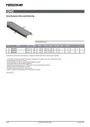
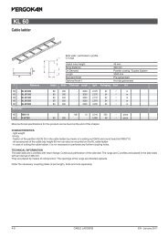
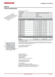
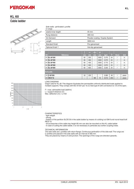
<strong>KL</strong><strong>KL</strong> <strong>60</strong><strong>Cable</strong> <strong>ladder</strong>Side walls : perforated L-profileC-rungsUseful inner heightRung distanceOn DemandLengthStandard finishOptional finish 145 mm300 mmPowder coating / Duplex System3000 mmPre-galvanisedHot-dip galvanisedHDReferenceCmmNmmKœLmm2mm kg/m u Stock UnitHD <strong>KL</strong> <strong>60</strong>*200 <strong>60</strong> 200 - 3000 2.370 24 P mHD <strong>KL</strong> <strong>60</strong>*300 <strong>60</strong> 300 - 3000 2.570 24 P mHD <strong>KL</strong> <strong>60</strong>*400 <strong>60</strong> 400 - 3000 2.770 24 P mHD <strong>KL</strong> <strong>60</strong>*500 <strong>60</strong> 500 - 3000 2.970 24 P mHD <strong>KL</strong> <strong>60</strong>*<strong>60</strong>0 <strong>60</strong> <strong>60</strong>0 - 3000 3.200 24 P mTo fix with:HD V <strong>60</strong>*200 50 200 - - 0.080 48 P pieceHD VM 6*10 - - M6 10 0.010 250 P pieceLOAD DIAGRAMGraph valid for <strong>KL</strong> <strong>60</strong>. This diagram illustrates the permissible uniformly distributed loads applied tomultiple supports. They comply with IEC 61537 par 10.3.3 test type III with connection to 1/5 of the span.F = max. admissible load (daN/m)L = support distance (m)Max. deflection (m) = L/100CHARACTERISTICS- light weight- strong- fixation of the partition SLOS 35 in the cable <strong>ladder</strong> by means of a sliding nut GM 6 and round head boltRB 6*10- all accessories of the cable tray height <strong>60</strong> mm can also be mounted on this <strong>KL</strong> cable <strong>ladder</strong>- in case of cutting the cable <strong>ladder</strong>, it is not necessary to perforate any further coupling holes.TECHNICAL INFORMATIONThe side walls are L-profiles with return flange. Continuous perforation of the side-wall. The rungs areC-profiles and placed in the side walls with an interval of 300 mm.They are placed by means of cold junction. The openings of the rungs are directed upwards.CABLE LADDERSEN - April 2012
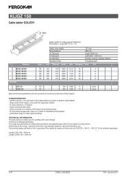
<strong>KL</strong><strong>KL</strong> 85<strong>Cable</strong> <strong>ladder</strong>Side walls : perforated L-profileC-rungsUseful inner heightRung distanceOn DemandLengthStandard finishOptional finish 170 mm300 mmPowder coating / Duplex System3000 mmPre-galvanisedHot-dip galvanisedHDReferenceCmmNmmKœLmm2mm kg/m u Stock UnitHD <strong>KL</strong> 85*200 85 200 - 3000 2.770 18 mHD <strong>KL</strong> 85*300 85 300 - 3000 2.970 18 mHD <strong>KL</strong> 85*400 85 400 - 3000 3.170 18 mHD <strong>KL</strong> 85*500 85 500 - 3000 3.370 18 mHD <strong>KL</strong> 85*<strong>60</strong>0 85 <strong>60</strong>0 - 3000 3.<strong>60</strong>0 18 mTo fix with:HD V 85*200 75 200 - - 0.130 48 P pieceHD VM 6*10 - - M6 10 0.010 250 P pieceLOAD DIAGRAMGraph valid for <strong>KL</strong> 85. This diagram illustrates the permissible uniformly distributed loads applied tomultiple supports. They comply with IEC 61537 par 10.3.3 test type III with connection to 1/5 of the span.F = max. admissible load (daN/m)L = support distance (m)Max. deflection (m) = L/100CHARACTERISTICS- light weight- strong- fixation of the partition SLOS <strong>60</strong> in the cable <strong>ladder</strong> by means of a sliding nut GM 6 and round head boltRB 6*10- all accessories of the cable tray height <strong>60</strong> mm can also be mounted on this <strong>KL</strong> cable <strong>ladder</strong>- in case of cutting the cable <strong>ladder</strong>, it is not necessary to perforate any further coupling holes.TECHNICAL INFORMATIONThe side walls are L-profiles with return flange. Continuous perforation of the side-wall. The rungs areC-profiles and placed in the side walls with an interval of 300 mm.They are placed by means of cold junction. The openings of the rungs are directed upwards.CABLE LADDERSEN - April 2012
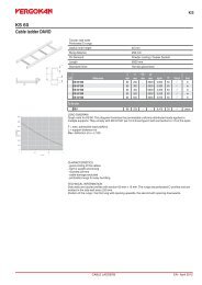
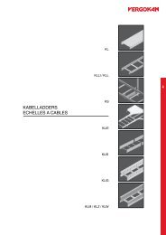
<strong>KL</strong>S<strong>KL</strong> <strong>60</strong>Rising cable <strong>ladder</strong> <strong>KL</strong>Side walls : perforated L-profileC-rungs 41*21 mmUseful inner heightRung distanceOn DemandMax. loadLengthStandard finishOptional finish 139 mm500 mmPowder coating / Duplex System114 kg/rung3000 mmPre-galvanisedHot-dip galvanisedHDReferenceCmmNmmKœLmm2mm kg/m u Stock UnitHD S<strong>KL</strong> <strong>60</strong>*200 <strong>60</strong> 200 - 3000 2.430 24 mHD S<strong>KL</strong> <strong>60</strong>*300 <strong>60</strong> 300 - 3000 2.670 24 mHD S<strong>KL</strong> <strong>60</strong>*400 <strong>60</strong> 400 - 3000 2.930 24 mHD S<strong>KL</strong> <strong>60</strong>*500 <strong>60</strong> 500 - 3000 3.070 24 mHD S<strong>KL</strong> <strong>60</strong>*<strong>60</strong>0 <strong>60</strong> <strong>60</strong>0 - 3000 3.330 24 mTo fix with:HD V <strong>60</strong>*200 50 200 - - 0.080 48 P pieceHD VM 6*10 - - M6 10 0.010 250 P pieceCABLE LADDERSEN - April 2012