KS 60 Cable ladder DAVID - Vergokan
KS 60 Cable ladder DAVID - Vergokan
KS 60 Cable ladder DAVID - Vergokan

You also want an ePaper? Increase the reach of your titles
YUMPU automatically turns print PDFs into web optimized ePapers that Google loves.
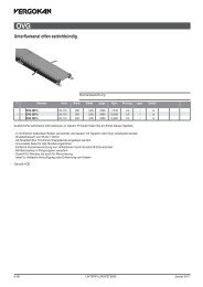
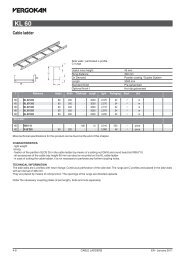
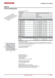
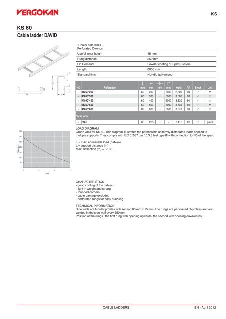
<strong>KS</strong><strong>KS</strong> <strong>60</strong><strong>Cable</strong> <strong>ladder</strong> <strong>DAVID</strong>Tubular side wallsPerforated C-rungsUseful inner heightRung distanceOn DemandLengthStandard finish45 mm250 mmPowder coating / Duplex System<strong>60</strong>00 mmHot-dip galvanisedHDReferenceCmmNmmKœLmm2mm kg/m u Stock Unit- <strong>KS</strong> <strong>60</strong>*200 <strong>60</strong> 200 - <strong>60</strong>00 2.800 <strong>60</strong> P m- <strong>KS</strong> <strong>60</strong>*300 <strong>60</strong> 300 - <strong>60</strong>00 3.080 <strong>60</strong> P m- <strong>KS</strong> <strong>60</strong>*400 <strong>60</strong> 400 - <strong>60</strong>00 3.320 <strong>60</strong> P m- <strong>KS</strong> <strong>60</strong>*500 <strong>60</strong> 500 - <strong>60</strong>00 3.530 <strong>60</strong> P m- <strong>KS</strong> <strong>60</strong>*<strong>60</strong>0 <strong>60</strong> <strong>60</strong>0 - <strong>60</strong>00 3.870 <strong>60</strong> P mTo fix with:- SSU 66 225 - - 0.410 20 P pieceLOAD DIAGRAMGraph valid for <strong>KS</strong> <strong>60</strong>. This diagram illustrates the permissible uniformly distributed loads applied tomultiple supports. They comply with IEC 61537 par 10.3.3 test type III with connection to 1/5 of the span.F = max. admissible load (daN/m)L = support distance (m)Max. deflection (m) = L/100CHARACTERISTICS- good cooling of the cables- light in weight and strong- rounded corners- cable damage excluded- perforated rungs for easy bundlingTECHNICAL INFORMATIONSide walls are tubular profiles with section <strong>60</strong> mm x 15 mm. The rungs are perforated C-profiles and arewelded in the side wall every 250 mm.Position of the rungs : the first rung with opening upwards, the second with opening downwards.CABLE LADDERSEN - April 2012
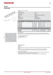
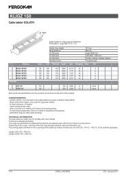
<strong>KS</strong><strong>KS</strong>R <strong>60</strong><strong>Cable</strong> <strong>ladder</strong> <strong>DAVID</strong> round rungsTubular side wallsRound rungsUseful inner heightRung distanceOn DemandLengthStandard finish33 mm250 mmPowder coating / Duplex System<strong>60</strong>00 mmHot-dip galvanisedHDReferenceCmmNmmKœLmm2mm kg/m u Stock Unit- <strong>KS</strong>R <strong>60</strong>*200 <strong>60</strong> 200 - <strong>60</strong>00 2.700 <strong>60</strong> m- <strong>KS</strong>R <strong>60</strong>*300 <strong>60</strong> 300 - <strong>60</strong>00 2.940 <strong>60</strong> m- <strong>KS</strong>R <strong>60</strong>*400 <strong>60</strong> 400 - <strong>60</strong>00 3.180 <strong>60</strong> m- <strong>KS</strong>R <strong>60</strong>*500 <strong>60</strong> 500 - <strong>60</strong>00 3.430 <strong>60</strong> m- <strong>KS</strong>R <strong>60</strong>*<strong>60</strong>0 <strong>60</strong> <strong>60</strong>0 - <strong>60</strong>00 3.670 <strong>60</strong> mLOAD DIAGRAMGraph valid for <strong>KS</strong>R <strong>60</strong>. This diagram illustrates the permissible uniformly distributed loads applied tomultiple supports. They comply with IEC 61537 par 10.3.3 test type III with connection to 1/5 of the span.F = max. admissible load (daN/m)L = support distance (m)Max. deflection (m) = L/100CHARACTERISTICS- good cooling of the cables- light in weight and strong- rounded corners- cable damage excludedTECHNICAL INFORMATIONSide walls are tubular profiles with section <strong>60</strong> mm x 15 mm.Rungs made of a Ø 19 mm tube.Connection between rungs and side walls by means of a double flange every 250 mm.CABLE LADDERSEN - April 2012