magnetic stirrers MCS66/MCS67 - FineMech
magnetic stirrers MCS66/MCS67 - FineMech
magnetic stirrers MCS66/MCS67 - FineMech

You also want an ePaper? Increase the reach of your titles
YUMPU automatically turns print PDFs into web optimized ePapers that Google loves.
IngenieurbüroM. Zipperer GmbHEtzenbach 16D-79219 StaufenInstruction Manual<strong>magnetic</strong> <strong>stirrers</strong> <strong>MCS66</strong>/<strong>MCS67</strong><strong>MCS66</strong>/67 - an innovation in microprocessor controlled <strong>magnetic</strong> <strong>stirrers</strong> microprocessor driven back-lit alphanumeric LC-Display fuzzy-logic and PID control Simultaneous display of temperature and speed PT100 sensor for temperature control safety temperature Soft motor start/stop adjustable safety temperature multistep timer functions RS232 interface for computer control switch off Timer (1 min - 99 days) membrane keypad
Table of Contents1.0 General Information ...................................................................................................................... 31.1 Unpacking the Instrument ................................................................................................ 41.2 Setting up the instrument ................................................................................................. 41.3 Glossary on LCD display .................................................................................................. 52.0 The Front Panel Controls .............................................................................................................. 62.1 Description of the front panel functions ........................................................................... 63.0 Stirring ......................................................................................................................................... 74.0 Hotplate function ........................................................................................................................... 74.1 Temperature control with an external PT100 probe - Probe Temp. ................................ 84.2 Temperature control without an external PT100 probe ................................................... 84.3 Setting the plate limit temperature - Plate Lim ................................................................. 84.4 Setting the Safety temperature - Safety Temp................................................................. 95.0 Timer controlled operation (standard timer) ................................................................................. 96.0 Multifunction Timer ....................................................................................................................... 106.1 Modifying the Timer Settings ........................................................................................... 116.2 Modifying the Timer Options ............................................................................................ 126.3 Starting the Multifunction Timer ....................................................................................... 126.4 Stopping the Multifunction Timer ..................................................................................... 126.5 Application Example ........................................................................................................ 137.0 Ramp controlled operation ............................................................................................................ 148.0 Description of the rear panel on the <strong>MCS66</strong>/67 ........................................................................... 159.0 Additional safety features ............................................................................................................. 169.1 Differential alarm - the safety power cut-out .................................................................... 169.2 Out of liquid check ........................................................................................................... 169.3 Failure of internal plate temperature sensor .................................................................... 169.4 Failure of external PT100 probe ...................................................................................... 169.5 Possible over-heating inside the <strong>MCS66</strong>/67 .................................................................... 1610.0 Changing basic settings .............................................................................................................. 1710.1 The Setup menu ............................................................................................................ 1710.2 The PID menu ................................................................................................................ 1910.3 The Calibrate menu ....................................................................................................... 2011.0 The serial interface ..................................................................................................................... 2111.1 Connection between PC and the <strong>magnetic</strong> stirrer ......................................................... 2111.2 Format of an RS232-Command .................................................................................... 2211.3 RS232 - COMMANDS <strong>MCS66</strong>/67 (Table 1) .................................................................. 2211.4 Format of the Controller Handshake .............................................................................. 2411.5 Writing parameters to the Controller .............................................................................. 2511.6 Reading parameters from the Controller ....................................................................... 2511.7 RS232-application example ........................................................................................... 2612.0 Error messages .......................................................................................................................... 2713.0 Maintenance ............................................................................................................................... 2714.0 Guarantee ................................................................................................................................... 2815.0 Technical Data ............................................................................................................................ 29version 1.04 page: 2
1.0 General InformationUnpack the instrument carefully and check to see that it is not damaged. It is important that any damageincurred in transport be reported at the time of unpacking. Notify your supplier and the carrier orforwarding agent immediately in case of such damage.Important Notice:Please read this instruction manual carefully before operating the instrument. Should you have anyadditional questions, after reading these instructions, concerning the setting up, operation or warrantyterms, please contact either your distributor or the manufacturer at the following address:Ingenieurbüro C A TM. Zipperer GmbHEtzenbach 16D-79219 StaufenTel. : (0) 7636-7803-0Fax. : (0) 7636-7803-45Safety Instructions:This instruction sheet does not purport to address all of the safety problems which might result from theuse of this instrument, chemicals, reagents, apparatus or equipment employed in any specific test orprotocols. It is the responsibility of the user to consult their authorized safety advisors and establishappropriate health and safety practices and then determine the application of regulatory limitations priorto use.Extreme caution should be exercised when handling corrosive, fuming, toxic and volatile or anyother potentially hazardous substances.1. Read the Operating Instructions thoroughly from cover to cover before beginning operation.Points of particular importance or safeguards, to be observed, should be highlighted ormarked for quick reference.2. Make sure that the voltage printed on the back of the unit corresponds to the voltage on yourmains.3. This Instruction Manual should be readily available to the operator and associatedpersonnel and be kept near the instrument, if possible.4. Only employ this instrument for the purpose intended by the manufacturer and particularlywithin the resistance limits of the instrument. If in doubt, contact your supplier or themanufacturer's factory representative at the phone number shown above.5. Always use the instrument in such a manner that neither the operator, nor any other personis endangered. Avoid splashes; use protective clothing, gloves and eye protection.6. Do not operate this instrument in environmentally unsafe areas and particularly in potentiallyexplosive atmospheres.7. Only use the manufacturer's authorized spare parts and accessories. Originalmanufacturers parts comply with strict tolerances and are produced to ensure reliability andextended service.8. In case of breakdown, do not attempt any type of repair. There are no parts inside theinstrument that should be serviced by the user. Repairs by the user may result in loss ofwarranty.version 1.04 page: 3
1.1 Unpacking the InstrumentUnpack the outer carton containing your instrument. If the carton exhibits any punctures, crushed sidewalls, chemical stains, water marks or other physical evidence that the contents may have beendamaged, notify your supplier and the carrier of the problem and ask for specific instructions.If there is no visible damage to the carton's exterior, open it in the normal manner. Please check that itcontains the following:1 <strong>MCS66</strong> / <strong>MCS67</strong> <strong>magnetic</strong> stirrer1 Instruction Manual1 PT100 temperature probe, if ordered with the <strong>MCS66</strong>/67Important Note:Assuming that the <strong>MCS66</strong>/67 and the PT100 probe have not been damaged and that all the above partswere identified, you can proceed with setting up the instrument after reading the instruction manual.This instrument has been designed with special materials and can be used for many tasks during dailylaboratory use. For materials which may come into contact with the system: See "Technical Data".Attention:The user must determine for himself the suitability of the instrument for the desired purpose. Shouldthere be any doubts always consult the distributor or manufacturer.1.2 Setting up the instrumentMake sure that the <strong>MCS66</strong>/67 is operated according to the conditions described in the sectionentitled Technical Data.Make sure that the voltage printed on the rear panel corresponds to the voltage from your mainspower supply.Attention:Do not allow the electrical power cable to touch the hotplate. The unit should be located on afire-proof surface.The unit is not to be used in potentially hazardous atmospheres or explosion-proof areas.version 1.04 page: 4
1.3 Glossary on LCD displayEDIT ARROW :Plate Temp.Plate Act.Probe SetProbe Act.TimerThis appears in the display when data input is required by selecting variouskeys. It stays on for three seconds, to allow the operator to set the values viathe up/down keys. Should the arrow disappear during data entry, just press thekey again.This function is for the following keys: Probe Temp. Plate Temp. Safety Temp. Timer RampThe hotplate temperature can be set in this mode.The display shows the actual hotplate temperature.The PT100 probe temperature can be set in this mode.The display shows the actual probe temperature.switch off time in days : hours : minutesDisplaying the System Info:press and hold the Display RPM key, whilst switching on the <strong>MCS66</strong>/67. The unitinitializes and then displays the system info screen. Press any key to displaythe next info.The System Info is shown on the LCD-display and contains the following information: total operation time (days:hours:minutes) number of times the <strong>MCS66</strong>/67 has been turned onversion 1.04 page: 5
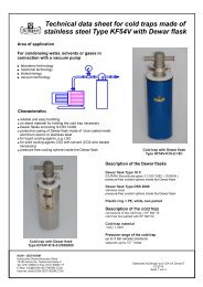
2.0 The Front Panel ControlsThe innovative keypad makes data entry easy and incorporates a 2-line alpha numeric LCD-displaywhich shows all relevant data. The entry and changing of settings is made via function keys and certainhot-keys.L CD -D i s p l a yu p -ke yd o w n -ke y(view of the <strong>MCS66</strong>/67 front panel)2.1 Description of the front panel functionsLCD displayPower On/OffMotor On/OffMotor RPMPlate ON/OFFPlate Temp.Probe Temp.Safety Temp.The LCD display shows all the relevant system dataPress this key to turn the unit on or off. When turning the unit off, alltemperature settings are stored in an EEPROM.Press this key to switch the stirring motor on or off.Press this key to initiate the edit arrow, which allows adjustment of themotor speed in connection with the up/down keys.Press this key to switch the hotplate on or off.Press this key to initiate the edit arrow, which allows adjustment of thetemperature via the up and down keys.Press this key to initiate the edit arrow, which allows adjustment of theprobe temperature via the up/down keys. The set temperature for theprobe is shown in the top line of the display. The actual probe temperatureis displayed in the bottom line.Press this key to initiate the edit arrow, which allows adjustment of thesafety temperature via the up/down keys. The temperature for the safetyprobe is shown in the top line of the display. The actual probe temperatureis displayed in the bottom line.version 1.04 page: 6
RampTimerIf required, pressing this key initiates the ramp function which will enablethe heating ramp function of the <strong>MCS66</strong>/67. The timer is calibrated toshow - days : hours : minutes.If required, pressing this key initiates the timer function which will shutdown the <strong>MCS66</strong>/67. The timer is calibrated to show - days : hours :minutes.3.0 StirringMake sure that the vessel to be used is permeable to <strong>magnetic</strong> field lines, e.g. glass, ceramic, stainlesssteel.N.B.:For optimum <strong>magnetic</strong> coupling use stirring bars of 20 - 80 mmpress Motor RPM to initiate the edit arrow, which allows adjustment of the motor speedin connection with the up/down keys.press Motor On/Off - key to switch the stirring motor on or off.The <strong>MCS66</strong>/67 has a motor soft-start feature which prevents liquid splashing andremoves the possible problem of de-coupling of the stirring bar.Attention:Avoid splashing of liquids by using a suitable vessel, lower liquid level, or by using a cover on top of thecontainer. Make sure that suitable protective clothing and eye-wear is used.This instruction sheet does not purport to address all of the safety problems which might result from theuse of this instrument, chemicals, reagents, apparatus or equipment employed in any specific test orprotocols. It is the responsibility of the user to consult their authorized safety advisors and establishappropriate health and safety practices and then determine the application of regulatory limitations priorto use.4.0 Hotplate functionFor the <strong>MCS66</strong>/67 <strong>magnetic</strong> stirrer, there are two modes of heating operation:heating with an external probe to control the liquid temperature (PT100)heating without an external probe (set the temperature of the hotplate)The desired temperature is set with the up/down keys. As long as the red "Heater" LED is either flashing,or on continuously, power will be applied, allowing the hotplate to reach the desired temperature. TheLED will go off when the set temperature has been reached. This LED is an additional visual signal toindicate whether the desired temperature has been reached.Warning: After switching off, the hotplate will stay hot.!! After use, always switch off the <strong>MCS66</strong>/67version 1.04 page: 7
4.1 Temperature control with an external PT100 probe - Probe Temp.For optimum results, we recommend the use of a external PT100 temperature probe, to preciselymonitor the temperature of the liquid being processed.By setting the PT100 probe temperature (ProbeSet) to monitor the liquid, the <strong>MCS66</strong>/67 automaticallyselects the optimum hotplate temperature to reach the desired liquid temperature in the fastest possibletime.connect the external PT100 probe to the socket marked PT100 at the rear of the <strong>MCS66</strong>/67press Power On/Off to switch the unit onpress Probe Temp. button to set the desired probe temperature (ProbeSet) with the up/down keys.press Plate Temp. button to set the maximum allowed hotplate temperature (PlateLim) for theheating process. This temperature should always be set as high as possible, to allow the <strong>MCS66</strong>/67fuzzy-logic control algorithms to select the optimum hotplate temperature freely. The PlateLimtemperature must always be set at least 10%-20% above the programmed probe-temperature !Otherwise the liquid can not reach the programmed temperature or the heat up time would becomeextremely long.put the PT100 probe into the vessel on the hotplate (immerse the PT100 tip at least 2cm into theliquid)press Plate On/Off to activate the hotplate (green control LED must be on).press Motor On/Off to switch on the stirring motor.Important Note:It is necessary to use only PT100´s with fully isolated tips, otherwise interference occur when the PT100tip touches any metal which is connected to earth, e.g. <strong>MCS66</strong>/67 casing, metal liquid container, etc.4.2 Temperature control without an external PT100 probepress Power On/Off to switch the unit onpress Plate Temp. button and then select the desired hotplate temperature with the up/down keyspress Plate On/Off to activate/deactivate the hotplatepress Motor On/Off to activate/deactivate the stirring motorN.B.:For normal operation, set the safety temperature and the plate limit temperature to their maximum values(320 °C) to achieve optimum regulation.Make sure that the plate limit temperature and the safety temperature are both set to appropriate valuesto prevent possible hazardous operation.If the probe temperature is set above the safety or plate limit temperature, the safety and the plate limittemperature will be automatically readjusted 10 % higher than the probe temperature.To set the safety or the plate limit temperature closer to the probe temperature, first adjust the probetemperature, then set the safety and the plate limit temperature.4.3 Setting the plate limit temperature - Plate LimSetting the plate limit temperature is only possible when using an external PT100 probe. To set thehotplate limit temperature: press Plate Temp.-key to initiate the edit arrow, which allows adjustment of the Plate temperature inconnection with the up/down keys (temperature measured at the hotplate).version 1.04 page: 8
4.4 Setting the Safety temperature - Safety TempIf the unit is operated with an external PT100 probe and the liquid temperature exceeds the safetytemperature (temperature measured with the external probe) the unit will shut down.Conversely, if the unit is operated without an external probe and the temperature measured at thehotplate (internal sensor) exceeds the safety temperature, the unit will also shut down. To set the safetytemperature:press Safety Temp.-key to initiate the edit arrow, which allows adjustment of the safety temperaturein connection with the up/down keys.5.0 Timer controlled operation (standard timer)The standard Timer function can be activated by once pressing the Timer key. The Edit arrow appears inthe display line and the time can be changed in increments of one minute with the up/down keys. If thetime is set to zero, the timer function is disabled. If, for example, a time of ten minutes is selected, the unitwill shut down after ten minutes. This standard Timer is used to automatically switch off the units after aprogrammed time has expired.The time entered has the following format: days : hours : minutesTherefore a reading like: 2: 5:45 is equal to five days, 5 hours and 45 minutes.This function is available for both stirring and heated stirring operation. press the Timer-key ounce to initiate the edit arrow, which allows adjustment of theTimer-settings in connection with the up/down keys.version 1.04 page: 9
6.1 Modifying the Timer SettingsTo modify the multifunction timer settings, press and hold the Timer key for more than three seconds.Press the up/down keys until 'Timer Settings' appears on the bottom line of the display, then press Timerkey to call up the timer-edit menu. Any other key exits the timer menu and resumes to normal operation.If the multifunction-timer is already running, the timer must be stopped prior to modifying the timersettings.From the timer edit-menu select the timer step (1-4) to edit (use up/down arrows). Then press the Timerkey to edit the desired multifunction timer step, or any other key to leave the timer-edit menu.The following settings can be modified in the Timer Settings menu for each timer step:settingexplanation[Tx] Exec. Time execution time of timer step x (1-4)Format: days:hours:minutes:seconds(0:0:0:0 will disable/skip the timer step)[Tx] Motor Rpmmotor speed of timer step x in rpmAn entry of 0 Rmp. will disable the motor[Tx] Plate Temp.hotplate temperature in °C for timer step xAn entry of 0°C will switch-off the hotplate.[Tx] Probe Temp.external probe temperature in °C for timer step xThis entry is only relevant if an external probe is connected ![Tx] Ramp [°C/min]temperature gradient of liquid temperature (external probe) for timerstep x in °C/h.To disable the ramping (=maximum heat up time), set the ramp-valueto 450°C/h.Default: 450°C/h = ramp disabled)This entry is only relevant if an external probe is connected !To skip a timer step, set its execution time to 0:0:0:0, this step would then not be evaluated during timerexecution.Note:Use the up/down keys to modify a setting. To confirm a setting press the Timer key. Any other keyreturns to the timer-edit menu and allows to select an other timer-step for edit.version 1.04 page: 11
6.2 Modifying the Timer OptionsTo modify the multifunction timer options, press and hold the Timer key for more than three seconds.Press the up/down keys until 'Timer Options' appears on the bottom line of the display, then press theTimer key to call up the timer-options menu. Any other key exits the timer-menu and resumes to normaloperation.The following options can be modified/defined in the timer-options menu:optionTimer cyclesexplanationwhen the last timer step of the 4 possible timer steps has beenexecuted, the <strong>MCS66</strong>/67 can automatically restart an other timercycle.This option defines how many cycles have to be executed.An entry of 0 for this option will let the timer cycle endlessly.Timer expired- Stand-BY- switch OFF- turn plate OFF- HOLD settingsThis option defines what to do after all timer cycles have beenexecuted:hotplate and motor switches off, unit stays on.the <strong>MCS66</strong>/67 shuts down (power off)The <strong>MCS66</strong>/67 stays on, but the hotplate is switched off, motor is leftunchanged with the settings of the last executed timer-step.The <strong>MCS66</strong>/67 holds the settings of the last executed timer-step(temperature and speed)6.3 Starting the Multifunction TimerTo start the multifunction timer, press and hold the Timer key for more than three seconds.Press the up/down keys until 'Start Timer' appears on the bottom line of the display.Press the Timer key to start the multifunction timer, or any other key to leave the timer-menu.Note:If the multifunction timer is running the Timer LED is blinking.6.4 Stopping the Multifunction TimerIf the multifunction timer is running (Timer LED is blinking), press the Timer key for more than threeseconds. Press the up/down keys until 'Stop Timer' appears on the bottom line of the display. PressTimer to stop the multifunction timer, or any other key to leave the timer-menu.version 1.04 page: 12
6.5 Application ExampleBy using two timer steps, the <strong>MCS66</strong>/67 can perform the following task:Settings of timer-step 1:setting explanation value[T1] Exec. Time execution time 90 minutes[T1] Motor Rpm motor speed 500 rpm[T1] Plate Temp. max. hotplate temperature 300 °C[T1] Probe Temp. probe temperature 150 °C[T1] Ramp [°C/min] temperature ramp 100 °C/hourSettings of timer-step 2:setting explanation value[T2] Exec. Time execution time 30 minutes[T2] Motor Rpm motor speed 700 rpm[T2] Plate Temp. max. hotplate temperature 300 °C[T2] Probe Temp. probe temperature 50 °C[T2] Ramp [°C/min] temperature ramp 200 °C/hourThe execution time of timer-steps 3 and 4 must be set to 0:0:0:0, to disable these steps.Multifunction Timer options:option explanation valuecycles number of cycles 1Timer expired END conditions HOLD settingsversion 1.04 page: 13
7.0 Ramp controlled operationThe ramp function allows for generating precise defined temperature gradients in the liquid. To haveaccess to the ramp function an external PT100 probe must be connected !The heating ramp function can be activated by pressing the Ramp key. The Edit arrow appears in thedisplay line and the desired maximum slope of the liquid temperature can be changed in increments of1°C/h with the up/down keys. If the ramp-value is set to 450°C/hour, the ramp function is disabled.This function is available for both stirring and heated stirring operation.press the Ramp-key to initiate the edit arrow, which allows adjustment of the ramp-setting inconnection with the up/down keys.Example:If, for example, a heating ramp of 50°C/hour is selected and the actual probe temperature at thebeginning is 100°C and the set temperature is 150°C, the unit will reach the set temperature in one hour.Note:- Ramp controlled operation is only possible when using an external PT100 probe.- The ramp function can also be used for slowly cooling down liquids.The ramp function only limits the maximum temperature increase/decrease per time. If the realtemperature in the liquid can follow the internal calculated temperature curve, depends of course also onother factors like: the heat capacity of the liquid, the room temperature... . Therefore if for example avessel with 6 liters of water should be heated to 90°C with a ramp-value of 400°C/h the unit of coursewould not be able to reach the programmed liquid temperature profile as the heat capacity is too high.version 1.04 page: 14
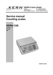
8.0 Description of the rear panel on the <strong>MCS66</strong>/67(rear view of the <strong>MCS66</strong>/67)On the rear panel of the <strong>MCS66</strong>/67, you will find 2 sockets and the mains cable.PT100 probeRS232 interfacemains power supplyconnection socket for the external PT100 probeconnection socket for the RS232 interface (remote control via PC)make sure that the voltage printed on the <strong>MCS66</strong>/67 corresponds to thevoltage from your mains.Connection of PT100 probe:514+9V23RTD PT100GROUNDImportant Note:It is necessary to use only PT100s with fully isolated tips, otherwise interference occur when the PT100tip touches any metal which is connected to earth, e.g. <strong>MCS66</strong>/67 casing, metal liquid container, etc.version 1.04 page: 15
9.0 Additional safety features9.1 Differential alarm - the safety power cut-outFailure of the stirring vessel could create a hazardous situation, so to solve this problem this instrumenthas a 'differential alarm' feature. The 'differential alarm' switches the unit off if the probe has fallen out ofthe liquid (e.g. failure of the stirring vessel, breakage of glass).The 'differential alarm' operates, if the temperature fall detected by the PT100 exceeds the differentialalarm sensitivity (see changing basic settings). Without a 'differential alarm', the unit will sense a too lowprobe-temperature which results in a fast rise of the hotplate temperature.If this function is not required, the 'differential alarm' can be switched off by pressing and holding theSafety Temp.-key, while switching the unit on.9.2 Out of liquid checkThe <strong>MCS66</strong>/67 monitors, whether the PT100 tip is immersed in the liquid in the vessel on the hotplate.The microprocessor checks whether the probe temperature changes in relation to the temperaturechanges of the hotplate. If the microprocessor detects no increase in the liquid temperature over acertain time, although the hotplate temperature is rising, a warning message is shown on the display, thehotplate is switched off and the <strong>MCS66</strong>/67 shuts down after a defined time (switch off time - basicsettings).N.B:This Safety feature is only available if the set temperature is a minimum of 10°C higher than the actualliquid temperature.The sensitivity of this liquid monitor can be defined in the basic settings of the <strong>MCS66</strong>/67 (Out of Liq.). Itmay be necessary to reduce the sensitivity level of this function, if the unit accidentally detects an Out ofLiquid situation, although the PT100 tip is fully immersed in the liquid. This could be necessary whenoperating with larger volumes of liquid, or with liquids that have a very high heat capacity.9.3 Failure of internal plate temperature sensorIf the internal plate temperature sensor breaks or the hotplate becomes warmer than 360°C the unit willimmediately shut down.9.4 Failure of external PT100 probeDisconnection or failure of the external PT100 probe will disable the heating of the hotplate. In case of afailure the unit shuts down immediately.9.5 Possible over-heating inside the <strong>MCS66</strong>/67If the temperature inside the <strong>MCS66</strong>/67 exceeds 95°C the unit will shut down immediately. This safetyfeature is fully "redundant". The unit either shuts down if the microprocessor measures a temperaturehigher than 95°C, or if the thermo-switch (inside the <strong>MCS66</strong>/67) detects a temperature higher than 95°C.version 1.04 page: 16
10.0 Changing basic settingsFor optimum adaptation of the <strong>MCS66</strong>/67 to all kinds of heating tasks and safety requirements, the unitprovides a setup-function were all relevant parameters can be adjusted.These global settings are stored in an EEPROM. To modify these settings press and hold the Timer key,while switching the unit on with the Power On/Off key.Choose one of the following menus, by pressing the up/down keys and then selecting the required menuby pressing Probe Temp.Setup MenuCalibrate MenuPID Adjustment10.1 The Setup menuThe following settings could be adjusted in the setup menu:ask for volumeIf the system should be used with different amounts of liquidand an optimum heating time is required the <strong>MCS66</strong>/67could ask the user for the process volume after power-up. Ifthis function is required set 'ask for volume' to YES (up/downkeys).possible settings : YES / NOSee also: PID-menu -> volumemax. Plate Temp. °CUser selectable maximum hotplate limit (max. 320°C)During normal operation, the hotplate setpoint can not be sethigher than this value.factory setting: 300°CDiff. Alarm SensitivityThe differential alarm sensitivity in °C per minute.If the PT100 probe temperature drop exceeds the differentialalarm sensitivity and the differential alarm was not disabledthe unit will shut down immediately.The monitoring circuit of the differential alarm is onlyevaluated whilst the hotplate is switched on.factory setting: 10 °C/minN.B.:Normally the differential alarm is enabled. To disable thedifferential alarm, press and hold the ´Safety Temp.´ key,while turning the unit on.Out of Liq.checkThe <strong>MCS66</strong>/67 detects whether the PT100-probe is in theliquid.(This safety feature is only enabled, if the difference betweenSET and ACT Temp. of the probe is greater than 10 °C)0 - disabled -> function disabled3 - normal -> normal sensivity7 - high -> highest sensitivitysensitivity range: 0 .. 7; factory setting: 3RS232 AdressRS232 BaudrateSlaveAdress of the <strong>MCS66</strong>/67 (serial interface)Baudrate of the serial interface (1200-4800 Baud)version 1.04 page: 17
switch off time switch off time in : hours : minutes : secondsTo increase the safety margin in case the hotplate overheats,it is often useful for the unit to continue with the stirringfunction and not to switch off immediately.Should the probe temperature measured by the PT100probe exceed the safety temperature and the unit switchesoff immediately, the switch off time could be set to help cooldown the liquid. In case of this failure, the hotplate switchesoff immediately and the stirring motor continues to run for theset time. After the switch off time has expired the unit willcompletely shut down.If however the sensor temperature still increases to morethan 25% above the safety temperature the unit willimmediately switch off and does not wait until the switch offtime has expired.factory setting: 0h 5min 0secExample:steps to set the max. Plate Temp.:press and hold the Timer key, whilst switching on the <strong>MCS66</strong>/67. The unitinitializes and then switches into the Set up menu.N. B.:The Timer key must be pressed down until the Setup menu is on the display.press the up/down keys until the Setup menu occurs on the displaypress the Probe Temp. key to select the setup menu.press the up/down keys until max. Plate Temp. occurs on the displaypress the Timer key to edit the max. Plate Temp.press the up/down keys to adjust the max. Plate Temp.press the Probe Temp. key to leave the setup menu.press the Probe Temp. when the units asks to save the setup parameters.press Power ON/Off to switch off the unitGeneral:When editing the basic parameters, the Probe Temp. button is used to select or to leave a menu, or toconfirm a selection. The Timer button is used to change a displayed value. The Setup-menu can only beleft by pressing the Power On/Off key !version 1.04 page: 18
10.2 The PID menuThe following settings could be used to adapt (tune) the system to an optimum heatingperformance.volume in mlthermal resistanceThis value reflects the heat capacity of the liquid in thevessel. An increase of this value will result in a faster heat uptime. If a too high value is entered (much higher than the realexisting amount of liquid) this can result in an overshoot andoscillation of the liquid temperature. A too low setting of thisvalue will result in a very slow reaction of the system and alonger than necessary heat up time(default) factory setting: 400 mlThis value reflects the degradation of energy from the liquidto ambient temperature. This means that if there is a lot ofenergy needed (which comes from the hotplate) to hold thedesired liquid (probe) temperature, there is a low thermalresistance presentIf, for example water should be heated to 99°C at normalambient conditions, this would need much more than onlydouble the energy to heat water to 50°C.The standard setting of this value, when operating not tooclose to the boiling point of the liquid is approx. : 380If, however, a temperature close to the boiling temperatureshould be controlled, this value should be decreased to lowervalues to achieve a faster heat up time. To control water at98°C a value of 75 for the thermal resistance gives goodresults.Attention: The value of the thermal resistance should only bereadjusted from 380 (default) when operating close to theboiling point of the liquid, otherwise an extreme temperatureovershoot can occur !version 1.04 page: 19
10.3 The Calibrate menuThe following programs can be used to calibrate the PT100 probes (two point calibration).PT100-A zero CalPT100-A highCalfactory Calibr.Calibration program for the PT100 probe (0°C)Calibration program for the PT100 probe (60°C..450°C)restoring the factory calibration for PT100 probesteps to calibrate the PT100 probe:connect the PT100 probe to the <strong>MCS66</strong>/67press and hold the Timer key, whilst switching on the <strong>MCS66</strong>/67. The unitinitializes and then switches into the Main-Menu.N. B.:The Timer key must be pressed down until the Main-Menu is on the display.press the up/down keys until 'Calibrate-Menu' appears in the displaypress the Probe Temp. key to select the Calibrate Menupress the up/down keys until 'PT100-A zeroCal' appears in the displaypress the Probe Temp. key to select the zero Calibration program for thePT100 probeput the PT100 probe into 0°C liquid (water and ice flakes)press any key, when readywhen temperature reading has stabilized press any keypress the up/down keys, to select whether the unit should store theCalibration data (turn to YES)press Probe Temp. to confirm your selectionpress the Probe Temp. key to call up the Calibrate Menu againpress the up/down keys until 'PT100-B highCal' appears in the displaypress the Probe Temp. key to call up the Calibration program for thePT100 probe (high point) select the highCal temperature by pressing the up/down keys e.g. to 100°C put the PT100 probe into 100°C liquid (e.g. boiling water) press any key, when ready when temperature reading has stabilized press any key press the up/down keys, to select whether the unit should store theCalibration data (turn to YES)press Probe Temp. to confirm your selectionN.B.:We recommend to leave the PT100 probes at least 1 minute in the ice water (0° C liquid) until thetemperature is stabilized.To calibrate at a higher highCal temperature (e.g. calibrating the <strong>MCS66</strong>/67 with oil) set the highCaltemperature to your desired value by pressing the up/down keys.To cancel a selected calibration program (PT100-A) press Plate Temp.Important: The calibration must be carried out in the above mentioned order. This means, the zerocalibration must be carried out ahead of the high calibration !version 1.04 page: 20
Restoring the factory calibration valuesSteps to restore the factory calibration settings of the PT100 probe:press and hold the Timer key, whilst switching on the <strong>MCS66</strong>/67. The unitinitializes and then switches into the Main-Menu.N. B.:The Timer key must be pressed down until the Main-Menu is on the display.press the up/down keys until 'Calibrate-Menu' appears in the displaypress the Probe Temp. key select up the Calibrate Menupress the up/down keys until 'factory Calibr.' appears in the displaypress the Probe Temp. key to select the factory Calibration program for thePT100 probes (PT100 and safety probe) press the up/down keys, to select whether the unit should store the factorysettings (turn to YES)press Probe Temp. to confirm your selection11.0 The serial interfaceThe serial interface (RS232) of the <strong>MCS66</strong>/67 facilitates remote access of all controller functions as wellas readout and change of all system parameters (e.g. hotplate temperature, probe temperature, setupparameters etc.)A special daisy chaining feature facilitates chaining multiple Controllers via their serial interfaces onlythrough one PC-interface (RS232)To setup a daisy-chain, the transmit line (TxD) of the PC is connected to the receive line (RxD) of the firstcontroller. The transmit line of this controller is then connected to the receive line of the next controller inthe chain. The transmit line of the last controller in the chain is returned to the receive line of the PC,which closes the link and forms the ring connection.To adress a specific controller in a daisy-chain, each controller carries a so called SlaveAdress, whichcan be any number from 1 to 255 (factory setting: 1)parameters of the serial interface (1200-4800,8,N,1):Baudrate:1200/2400 or 4800 Baud (see Setup-Menu)Databits:8 BitParity:noneStopbits: 111.1 Connection between PC and the <strong>magnetic</strong> stirrerThe RS232 socket at the <strong>magnetic</strong> stirrer has the following pinout.descriptiontransmit datareceive datagroundDIN stereo socket<strong>MCS66</strong>/67TxDRxDGNDGNDTxDRxDversion 1.04 page: 21
The following RS232-commands can be sent by any terminal program via the serial interface to aController (<strong>magnetic</strong> stirrer). For quick and programming Windows Software program is available asan optional extra, to give the user instant PC control (LabControl for Windows).11.2 Format of an RS232-CommandADR , CMDCODE , PARAMETERLIST Description:ADR:CMDCODE:PARAMETERLIST:CR:SlaveAdress of the desired <strong>magnetic</strong> stirrerCommand-code1 to 6 parameters separated by commasThe command string must be terminated by Carriage/Return11.3 RS232 - COMMANDS <strong>MCS66</strong>/67 (Table 1)CMD. Explanation Parameter list RangeCODERSS Read system status 1. Dummy parameter to initiate transfer-> Controller sends in handshake:01. actual systemstatus code1 -> in command mode, ready1WONRONSet Status (ON/OFF control) of- Motor- PlateRead status of:(The <strong>MCS66</strong>/67 <strong>magnetic</strong> strirrer has only one operationmode. This command is only implemented for compatibilityreasons)2. Error code255 no error1 Plate temp. > safety temp.2 Probe temp. > safety temp.11 Out of liquid1. Motor ON/OFF (0-> Off, 1-> On)2. Plate ON/OFF (0-> Off, 1-> On)1. Dummy parameter to initiate transfer1,2,11,2550/10/11-> Controller sends in handshake:- Motor- Plate1. Motor On/Off (0-> off, 1-> on)2. Plate On/Off (0-> off, 1-> on)RAC Read actual 1. Dummy parameter to initiate transfer0/10/11WSERSEWrite actual set values of:- Motor- Hotplate (plate)- external PT100 sensor (probe)Read actual set values of:-> Controller sends in handshake1. actual motor speed2. actual plate temperature3. actual probe temperature if connected, if not 'x' asreturn value)1. Setpoint of motorspeed in Rpm2. Setpoint of hotplate temperature in °C3. Setpoint of probe temperature in °C1. Dummy parameter to initiate transfer0..16000..3400..250, x0..16000..3400..2501WTR- Motor- Hotplate (plate)- external PT100 sensor (probe)Set / Write:-Timer- Ramp- Safety temperature-> Controller sends in handshake:1. Setpoint of motorspeed in Rpm2. Setpoint of hotplate temperature3. Setpoint of probe temperature1. Timer value in seconds. Set this value to 0 to disable thetimer.2. setting of the ramp in °C/h (a value of 450 disables theramp)3. Safety temperature in °C0..16000..3400..2500.. 25920001.. 45020.. 450version 1.04 page: 22
RTRRead settings of:1. Dummy parameter to initiate transfer1WSDRSD- Timer- Ramp- Safety temperatureWrite setup data:- max. Plate temperature- switch off time- Ask for volume at power up- Differential alarm sensitivity- Out of liquid check sensitivity- Thermal resistanceRead setup data:-> Controller sends in handshake:1. actual setting of the timer in seconds. If the timervalue is0, the timer is disabled.2. setting of the ramp in °C/h (a value of 450 signals thatthe ramp is disabled)3. Safety temperature in °C1. max. Plate temperature2. switch off time3. Ask for volume at power up4. Differential alarm sensitivity5. Out of liquid check sensitivity6. Thermal resistance1. Dummy parameter to initiate transferController sends in handshake:0.. 25920001..45020..45020..3401..0/15..1000..750..4001- max. Plate temperature- switch off time- Ask for volume at power up- Differential alarm sensitivity- Out of liquid check sensitivity- Thermal resistance- max. Plate temperature- switch off time (delay time to power down after an error)- Ask for volume at power up (0-> no, 1-> yes)- Differential alarm sensitivity- Out of liquid check sensitivity (0-> off, 7->max)- Thermal resistance (default=380)20..3401..0/15..1000..750..400WVO Write/Set volume 1. Volume in ml 10..10000RVO Read volume 1. Dummy parameter to initiate transfer1-> Controller sends in handshake:1. programmed volume in mlWT2 Start multifunction timer 1 parameter1. start / stopRCO Read connector status 1. Dummy parameter to initiate transfer10..1000011/01RKYread keyboard and returnkeycode-> Controller sends in handshake:1. Connector status0 - not assigned1 - Contactthermometer mode2 - PT100 probe connected3 - PT100 probe broken4 - Connector error1. Dummy parameter to initiate transfer-> Controller sends in handshake:keycode 0..255WKY send key value to keyboard buffer 1. Key code 0..255OFF Switch unit OFF 1. security parameter to initiate transfer 1234WSARTYSet RS232 slave-adress,+ renumber slaves1. New slave-adress of controller 0...255Read Type and Version of device 1. Dummy parameter to initiate transfer10..4-> Controller sends in handshake:1. name/type of device2. Version number of softwareWEE Write parameters to EEPROM 1. Parameter setting to be stored in EEPROM1-> Actual settings (setpoints...)2-> Setup parameters3-> restore factory calibrationtextnumber1..3version 1.04 page: 23
11.4 Format of the Controller HandshakeAfter receiving an RS232-command the <strong>MCS66</strong>/67 will :1. Send the received command to the next <strong>MCS66</strong>/67 (or back to the PC - daisy chaining)2. Answer with a handshake string, which is defined as follows:ADR , "HS", RETCODE , PARAMETERLIST CRExplanation:ADR:RETCODE:SlaveAdress of the Controller sending the handshakeErrorcode (see table 2 below)PARAMETERLIST: 0 to 6 parameters (see table 1), each parameter is separated by a comma ","CRthe handshake as any command, is terminated by ASCII-code 13 (CR)TABLE 2:Return Code Explanation ParameterlistOK command executed, no error see table 1UC unknown command nonePA wrong parameter numbernone(too few or too many parametersspecified)NA command is not allowed in actualoperation modeactual operationmodePR at least one parameter is out of nonerangePL at least one parameter is too long noneDF unknown data format noneversion 1.04 page: 24
11.5 Writing parameters to the ControllerIf, for example: the motor speed of the motor should be 1000 rpm the max hotplate temperature should be 150 °C, and the probe temperature (ext. PT100 probe) should be 100 °Cthe following command string has to be sent to the controller with slave-address 1:1,WSE,1000,150,100The Controller then sends the following two strings to the next Controller (or back to the PC):1,WSE,1000,150,1001,HS,OKThe first string is the Echo of the received command.The second string indicates that the command was accepted and will be executed.11.6 Reading parameters from the ControllerTo readout the actual stirring speed send the following command to the Controller with SlaveAdress 1.1,RSE,1The <strong>MCS66</strong>/67 then sends the following two strings to the next Controller (or to back the PC):1,RSE,11,HS,OK,1000,150,100The first string is the Echo of the received command.The second string indicates that the command was accepted and will be executed it also contains thefollowing information (see table 2): the programmed motor speed is equal to 1500 rpm the programmed hotplate temperature is equal to 150°C the programmed probe temperature is equal to 100°Cversion 1.04 page: 25
11.7 RS232-application exampleExample: The <strong>MCS66</strong>/67 should be programmed to operate with the following settings:motorspeed:1250 rpmmax. hotplate temperature: 250 °Cprobe temperature: 75 °Csafety temperature: 80 °Cthe unit should shut down after 50 minutesthe ramping function of the liquid temperature should be disabled(It is assumed, that the <strong>MCS66</strong>/67 carries the RS232-slave adress 1, and that an PT100 probe isconnected)To program the unit with the above mentioned settings, the following commands have to be sent to the<strong>magnetic</strong> stirrer:1,WSE,1250,250,751,WON,1,11,WTR,3000,450,80; program setpoints. (motor, plate, probe); switch hotplate and motor ON; 50min=3000sec, 450=ramp off, safety=80°Cversion 1.04 page: 26
12.0 Error messagesThe <strong>MCS66</strong>/67 hotplate <strong>magnetic</strong> stirrer has been designed especially to be set up to operate completelyunsupervised. Therefore, it has an on-board self diagnostic program that detects possible failures and,should one occur, the <strong>MCS66</strong>/67 shuts itself down. To enable the user to prevent the problemre-occurring, the <strong>MCS66</strong>/67 will display any of the following error messages as it is switched on again.Please read carefully the following table of error messages.Error message:Reason for shut down:hotplate failure the hotplate temperature has exceeded 360 °Cthe hotplate temperature sensor is broken or damagedPlate > Safetythe measured plate temperature was greater than the safety temperatureProbe > Safetythe measured probe temperature was greater than the safety temperatureTIMER expiredNo Liq. contactDifferential ErrProbe failureTriac failurePlate SensorFailthe timer has expired (timer key)The "Liquid detection" circuit of the <strong>MCS66</strong>/67 has detected a too slow change in the temperaturemeasured by the external PT100 probe, while a significant increase of the hotplate temperature wasmeasured and the plate was switched on. The sensitivity of this safety circuit can be changed or disabled inthe setup menu.When operating with extremely large volumes, it can be necessary to set the sensitivity of this alarm to avery low level or even disable it.Differential AlarmThe differential alarm was triggered (Temperature measured by the PT100 probe dropped too fastalthough the plate was switched on). This error can be triggered if the probe is taken out of hot liquid, whilethe plate is switched on. The sensitivity of the differential alarm circuit can be changed in the setup menu.The external PT100 probe has failed (e.g. broken or short circuit)This error message can also occur if the PT100 probe is disconnected while the unit is runningThe Triac for hotplate heating is damaged.This alarm is triggered if the hotplate temperature still increases fast, although the plate is switched off.This error can accidentally be triggered, if the hotplate is switched off during a fast heat up of the hotplate.To verify if the triac for heating has really blown out, switch the unit off and let it cool down. Then switch theunit on (Plate must stay turned off). If a triac failure message is not again displayed within two minutes, thetriac works ok.the hotplate temperature sensor is broken or damaged13.0 MaintenanceThe outer housing of the <strong>MCS66</strong>/67 consists of a coated aluminum casing, together with an anodizedaluminum hotplate and a chemically resistant splash-proof membrane key-pad and therefore is easilycleaned with warm water and any proprietary liquid laboratory detergent. Do not use steel wool or anysimilar plastic wool sponge to clean the unit.In case of malfunction do not attempt to repair the unit. There are no user-serviceable parts inthis instrument.The CAT <strong>MCS66</strong>/67 should only be opened and repaired by authorized service personnel. Any work onthe electronics in the unit should only be carried out by knowledgeable, trained personnel. Any attempt bythe user to repair the unit will immediately render the guarantee null and void. Please contact your localdistributor in the event of a problem.version 1.04 page: 27
14.0 GuaranteeThe manufacturer agrees to either repair, or replace, at the manufacturer's discretion, any defects inmaterials or workmanship which develop within 12 months of the delivery of this product to the originaluser. In the event of replacement, the replacement unit will be guaranteed for the remainder of theoriginal twelve (12) month period or ninety (90) days, whichever is longer.If this product should require service, contact your local distributor or manufacturer for necessaryinstructions.This guarantee will not apply if the defect or malfunction was caused by accident, neglect, unreasonableuse or fitness for a particular purpose, which extend beyond the description and period set forth herein.The manufacturer's sole obligation under this guarantee is limited to the repair or replacement of adefective product and the manufacturer shall not, in any event, be liable for any incidental orconsequential damages of any kind, resulting from use or possession of the product.Attention:The user has to determine, if the instrument is suitable for his specific application. If there are any furtherqueries, contact your local dealer or the manufacturer direct.version 1.04 page: 28
15.0 Technical DataType <strong>MCS66</strong>/67Electrical power requirementsDisplayHotplateHeating powerSpecifications110/230 Volts; 50/60 Hz (see <strong>MCS66</strong>/67 rear panel)bright, backlit LCD display, showing all relevant system data<strong>MCS66</strong>: anodized Aluminum<strong>MCS67</strong>: Ceran hotplate<strong>MCS66</strong>: 500 watts<strong>MCS67</strong>: 600 wattsMotor specification microprocessor controlled soft start logic steplessly adjustable, 50 - 1600 rpm split-pole, 40 wattsTemperature control microprocessor controlled - fuzzy logic adjustable hotplate temperature programmable hotplate temperature programmable PT100 probe temperature programmable safety temperature programmable temperature ramp rate 1°C/hour to 450°C/hourMultistep safety systemSwitch-off time delayMeasuring sensor for mediumdetects and protects against the following hazardous situations:self test of all safety functions after switching onhotplate failure (hotplate exceeds max. allowed temperature)probe failure (disconnection or break of PT100 probe)detection of out-of-liquid condition, e.g. stirring vessel breaksdifferential safety cut-out (external probe senses an extreme fall intemperature of liquid being stirred)triac failureprogrammable switch-off time delay of stirring function, should thehotplate shut down, to allow the liquid to cool down more quickly.platinum resistance temperature probeAuxiliary functions two point calibration for external PT100 probes user programmable maximum hotplate temp. (20-320°C)setting accuracy 0.5 °CTemperature deviation with PT100probeMagnetic stirring barPermissible ambient temperaturePermissible humiditySafety class acc. to DIN 40050Case dimensionsHotplate dimensionsWeight 0.3 °Cmax. length: 80 mmmax. diameter: 10 mm5 - 40 °C within operating area, e.g. fume cupboard80 % RHIP42210 x 145 x 105 mm140 mm 2.6 KgRevNr: 1.00.01version 1.04 page: 29