Advanced Materials and Processes for Large, Lightweight, Space ...
Advanced Materials and Processes for Large, Lightweight, Space ...
Advanced Materials and Processes for Large, Lightweight, Space ...
- No tags were found...

You also want an ePaper? Increase the reach of your titles
YUMPU automatically turns print PDFs into web optimized ePapers that Google loves.
AMPTIAC is a DOD In<strong>for</strong>mation Analysis Center Administered by theDefense In<strong>for</strong>mation Systems Agency, Defense Technical In<strong>for</strong>mation Center
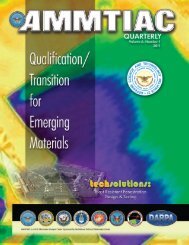
temperatures without increasing their figure or finish distortions).They could be employed in systems such as the JamesWebb <strong>Space</strong> Telescope (Figure 1), which is envisioned to replacethe Hubble <strong>Space</strong> Telescope.TRADITIONAL MATERIALS AND PROCESSESMonolithic Glass MirrorsSilica-based glasses have been used <strong>for</strong> hundreds of years asboth the optical <strong>and</strong> structural substrate <strong>for</strong> mirrors. Glassmakes a good optical substrate due to its low softening point,low hardness, <strong>and</strong> its absence of a grain structure (amorphous).This allows it to be <strong>for</strong>med, ground, <strong>and</strong> polished into complexshapes with precise figure (≅ λ/20 RMS *,† ) <strong>and</strong> very smoothsurface finishes (as low as ≅ 3Å RMS). Once the figure <strong>and</strong>finish requirements are met <strong>for</strong> a particular application, themirror is then coated with a very thin metal film whichprovides its reflective characteristics.Another benefit <strong>for</strong> using glass in mirror designs is that itsamorphous structure allows <strong>for</strong> a wide variation in chemistries.Varying the chemical composition of the elements contained inthe glass is a method used to adjust the coefficient of thermalexpansion (CTE) to values approaching zero at various usetemperatures. These mirror glasses provide dimensional stability(of the mirror figure) with respect to the thermal variationsof the environment. A brief review of glass chemistry showshow this was made possible.Silica-based glass is an inorganic material with a metastableamorphous structure (no long range order). Most glasses areproduced by supercooling their liquids to a rigid conditionwithout crystallization. Some glasses are prepared withoutcooling from the liquid state such as vapor grown or solutiongrown glasses. In either case, the atoms of a silicate glass <strong>for</strong>m acontinuous framework of silicon <strong>and</strong> oxygen atoms tetrahedronallybonded together at their corners. The bonds arestrong, but they have large variations in the Si-O-Si bond angle.Such a r<strong>and</strong>om network is not necessarily uni<strong>for</strong>m, <strong>and</strong> localvariations in density <strong>and</strong> structure are to be expected. Thisvariability in local density <strong>and</strong> bond angle allows the absorptionof thermally inducted vibrational energy through transversemodes of vibration <strong>and</strong> the adjustment of bond angles, resultingin a low CTE.Corning Glass uses a vapor growth process <strong>and</strong> a chemicalcomposition employing fused silica (SiO 2 ) <strong>and</strong> 7% (by weight)Titania (TiO 2 ) to produce its Ultra Low Expansion (ULE) glass[2]. One of the contractors under Air Force (AF) sponsorshiprecently produced this composition by a sol-gel approach [3].The CTE of a glass can also be tailored by the homogeneousprecipitation of negative CTE crystalline phases throughoutthe glass matrices. This is the case with Zerodur glass [4], aglass–ceramic system containing Li 2 O, Al 2 O 3 , <strong>and</strong> SiO 2 (LAS)with a small amount of TiO 2 . ULE <strong>and</strong> Zerodur both sufferfrom very low thermal conductivity, strength, modulus, <strong>and</strong>fracture toughness. Since they can be polished to a complicatedfigure with a very smooth surface finish, glasses such as ULE<strong>and</strong> Zerodur are good optical surfaces. However, since theyboth possess poor mechanical properties they may not be thebest material choice <strong>for</strong> a space-based mirror.To surmount the a<strong>for</strong>ementioned shortcomings in mechanicalproperties, thick <strong>and</strong> heavy mirror designs have typicallybeen used along with good h<strong>and</strong>ling <strong>and</strong> mounting practices.Reliability <strong>and</strong> robustness were assured in space-based systemsby encasing mirror systems into metallic tube structures.However, in future airborne <strong>and</strong> space-based mirror systems,where weight <strong>and</strong> size are constrained by payload requirements,this shielded approach, <strong>and</strong> high areal density design may notbe feasible. Non-shielded, low areal density designs may berequired to meet system goals; <strong>and</strong> robustness must be providedby either new structural substrate materials (with highmodulus, strength, <strong>and</strong> fracture toughness) or with new hybriddesigns.Metallic MirrorsBecause they are easily <strong>for</strong>med, machined, polished, h<strong>and</strong>led,<strong>and</strong> are relatively inexpensive, metals like aluminum <strong>and</strong>nickel have been used as mirror materials in terrestrial applications<strong>for</strong> years. Additionally, most metals are inherently highlyreflective, so they do not require coatings to yield high broadb<strong>and</strong>reflectivity. Un<strong>for</strong>tunately, they generally have high CTEsat ambient temperatures, which limit their applications.However at cryogenic temperatures below 70°K, beryllium hasa near zero CTE. This along with its low density, high stiffness,<strong>and</strong> cryogenic-thermal conductivity make it a desirable mirrormaterial <strong>for</strong> highresolutioninfraredimaging. Beryllium’sutility is compromisedby its highcost, toxicity, slowmachineability, <strong>and</strong>anisotropic behaviordue to its hexagonalcrystal structure.Processing by st<strong>and</strong>ardmetallic hotworking methodssuch as <strong>for</strong>ging <strong>and</strong>rolling results in texturingthat cannotCourtesy of NASAFigure 2. A 1.4 Meter Beryllium Mirror.be homogenized through recrystallization. This textured grainstructure results in an anisotropic modulus <strong>and</strong> thermal expansionbehavior of the mirror substrate. Only powder processessuch as hot isostatic pressing, vacuum hot pressing, sintering, orvacuum plasma spray will yield a r<strong>and</strong>omly oriented grainstructure that shows isotropic behavior (Figure 2).[5, 6, 7]Metals can also be used to create the optical substrate, whichis the polished material directly between the reflective surface<strong>and</strong> the structural substrate. Several manufacturers have usedpolycrystalline silicon as an optical substrate (also known as amirror cladding). Its isotropic behavior (diamond cubic structure),low density <strong>and</strong> CTE, high thermal conductivity <strong>and</strong>excellent polishability make it a good c<strong>and</strong>idate <strong>for</strong> an opticalsubstrate [8]. Polycrystalline silicon can be fabricated usingmelt/solidification, sintering, plasma spraying, physical vapordeposition (PVD), <strong>and</strong> chemical vapor deposition (CVD).Highly polishable single crystal silicon from the electronicsindustry has also been used as an optical substrate material on68The AMPTIAC Quarterly, Volume 8, Number 1
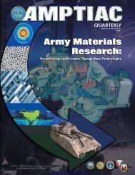
a flat mirror, but its size is limited to approximately 12 inchesby single crystal growth methods. A detriment to the use ofsilicon is that it has a low modulus <strong>and</strong> an affinity <strong>for</strong> atomicoxygen, which may limit its applicability <strong>for</strong> certain missions.NEW MATERIALS AND PROCESSESIncreasing the size of mirrors <strong>for</strong> space applications requiresthat new materials <strong>and</strong> processes be developed to reduce theareal density as compared to monolithic glass <strong>and</strong> metallicmirrors. One approach that has been under development <strong>for</strong>quite some time involves the use of monolithic glass sheets thatare bonded to a lightweight honeycomb core. Since an internalhoneycombed structure is used, this approach allows <strong>for</strong> thesame per<strong>for</strong>mance as a monolithic glass mirror but at a greatlyreduced weight. Another approach that has seen quite a bit ofdevelopment uses monolithic silicon carbide fashioned usingvarious fabrication techniques. Both of these methods arediscussed further in the following sections.<strong>Lightweight</strong> Monolithic Glass MirrorsSignificant ef<strong>for</strong>t has been made over the past twenty years toreduce the weight of airborne <strong>and</strong> space-based glass mirrors.These ef<strong>for</strong>ts were driven by needs to reduce launch costs,decrease thermal mass (to equilibrate temperatures in shortertimes), <strong>and</strong> to minimize the weight <strong>and</strong> complexity of thesupport <strong>and</strong> h<strong>and</strong>ling equipment.The Hubble <strong>Space</strong> Telescope mirror was a lightweightdesign. It was produced using a frit bonding process to joinindividual ULE glass plates to create an open-faced honeycombedcore structure[5]. The core was then frit bondedbetween two ULE glass face-sheets to produce a lightweightmirror blank. The mirror blank was ground, polished, <strong>and</strong>vapor coated with aluminum to create a visible light reflectivesurface. This mirror is 2.4 m (8 ft) in diameter <strong>and</strong> weighs 828kg (1820 lbs). It has an areal density of approximately 200kg/m 2 . The major problems encountered in building this mirrorwere thermal distortions <strong>and</strong> uneven stresses in the plates<strong>and</strong> joints. Additionally, the processing method was extremelylabor intensive, time-consuming, <strong>and</strong> expensive.Many programs have attempted to overcome the processingdifficulties experienced while building the Hubble mirror <strong>and</strong>to develop methods/processes to substantially reduce the arealdensity to less than that of the Hubble mirror. Most recently,the <strong>Advanced</strong> Mirror Systems Demonstrator (AMSD) program(run by NASA’s Marshall <strong>Space</strong> Flight Center), a jointly fundedef<strong>for</strong>t by the Air Force, NASA, <strong>and</strong> the NationalReconnaissance Office (NRO), attempted to advance the stateof-the-artin large, lightweight mirrors[5, 9].In the AMSD program, an abrasive water jet (AWJ) millingtechnique was used to fabricate thin-walled, open-ended,honeycomb core structure out of bulk ULE glass (Figure 3).The front <strong>and</strong> back faceplates were attached using a lowtemperature fusion bonding process; producing a honeycombs<strong>and</strong>wich-type design. A 1.4-meter wide hexagonal mirrorsegment is shown in Figure 4. This lightweight glass mirror segmentwas then attached to a carbon fiber-rein<strong>for</strong>ced compositereaction structure with 16 actuators. This total mirror systemhas an areal density of about 12 kg/m 2 . However, the contractorsappear to have reached the lower limit in areal density thatone can expect <strong>for</strong> a monolithic glass mirror. Any additionalreductions would have to come though hybrid materialapproaches, new materials, or composites. The AMSDCourtesy of NASAFigure 3. ULE HoneycombCore Produced by AWJMilling in the AMSDProgram.Figure 4. Kodak’s 1.4 Meter <strong>Lightweight</strong> Glass Mirror Segment.Courtesy of NASAThe AMPTIAC Quarterly, Volume 8, Number 1 69
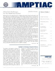
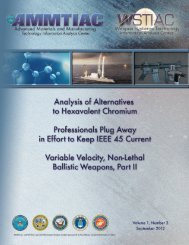
1000Fracture ToughnessSpecific StiffnessThermal Stability1001010.1AlBeSiC/MgFracture Toughness is in MPa-m 0.5 , SpecificStiffness is in Units of GPa-cc/gm, <strong>and</strong>Thermal Stability[§] (k/α) in W/m-ppm.C/AlSi-foamSinter-SiCC/SiCSi-SiC/SiCULEZerodurC/PyrexHM-C/EpoxyHD-C FoamFigure 5. A Comparison of Parameters <strong>for</strong> a Variety of Mirror Substrate C<strong>and</strong>idate <strong>Materials</strong>.contractors were also very successful in reducing the cost <strong>and</strong>fabrication time of a glass mirror to half that of a comparableHubble mirror.Silicon Carbide-Based MirrorsSilicon Carbide (SiC)-based materials are promising <strong>for</strong> use asstructural substrates in large mirrors because of their high specificstiffness (high modulus <strong>and</strong> low density) <strong>and</strong> their lowthermal distortion susceptibility (low thermal expansion <strong>and</strong>high thermal conductivity) (Figure 5). However, there aremany different types of SiC-based materials, <strong>and</strong> each willpolish differently producing variability in surface figure <strong>and</strong>finish. This variability comes from the differences in hardness<strong>and</strong> modulus between the phases present, their crystallography,<strong>and</strong> morphology.Pure SiC can be grouped into two crystalline <strong>for</strong>ms: 1) alpha(α-SiC), which has a rhombohedral or hexagonal structure <strong>and</strong>is produced when the <strong>for</strong>mation or processing temperatureexceeds 2000°C; <strong>and</strong> 2) beta (β-SiC), a face-centered cubicphase that is <strong>for</strong>med by processes that occur below 2000°C.The best surface finish <strong>for</strong> crystalline SiC would be expectedfrom a dense, fine equiaxed grain, single-phase, β-cubic structurebecause its hardness, strength, modulus, <strong>and</strong> thermalexpansion behavior should be isotropic <strong>and</strong> the grain shapeequiaxed.The highest density, smallest grain size, single-phase β-SiC isproduced by controlled re-nucleation using a CVD process.Since the deposition rates are rather slow, β-SiC is mainly used<strong>for</strong> depositing thick coatings or claddings (the optical substrate)onto less expensive, less dense, sintered, or siliconized (excesssilicon) SiC based materials (the structural substrate). The polishabilityof CVD β-SiC cladding material is limited by its highhardness. Too high a pressure on the polishing tool causes quilting-typeprint-through effects on lightweight honeycomb corestructures, while too low a pressure increases the polishing timemaking it uneconomical.However, β-SiC mirrors can be fashioned through othertechniques. <strong>Lightweight</strong>, near net-shaped β-SiC mirrors areproduced by taking a special grade of graphite <strong>and</strong> machiningit to the desired structure followed by conversion of thegraphite to silicon carbide through a gas phase reaction. Thisreaction process has a very small but predictable dimensionalchange. The as-converted β-SiC structure has approximately20% porosity. This mirror substrate is then cladded with CVDβ-SiC to make a 100% β-SiC mirror. It is then polished usingconventional optical polishing.Sintering of pure alpha (α-SiC) particles to full density is difficultunless both sub-micron powders <strong>and</strong> sintering aids areused. Powders <strong>and</strong> binders are usually mixed <strong>and</strong> isostaticallypressed at room temperature into a green body[‡] blank. Thegreen body can then be machined into an oversized geometrythat is predicted by sintering shrinkage models. The oversized,machined green body part is then sintered above 2100°C,resulting in approximately 17% linear shrinkage. The sinteredSiC component is approximately 97% dense <strong>and</strong> contains 98to 99% α-SiC, depending upon the amount of sintering aidsused. Sintered SiC produced by Boostec in France[10] has amorphology consisting of 5 µm grain size with 3% porosityshowing up as 1 to 2 mm voids along particle boundaries. A1.3 m sintered SiC demonstration mirror has been produced<strong>for</strong> the first near-IR telescope [11].For optical applications at shorter wavelengths, sintered SiCis coated with CVD SiC <strong>and</strong> the blank is ground, polished, <strong>and</strong>etched by an ion plasma beam. This Boostec-sintered (α-SiC)technology has recently been acquired in the USA by Coors Tekin Boulder, Colorado [12].Two-phased, siliconized-SiC is produced by several methods.The first method uses slip cast (α-SiC) powders followedby sintering until they are approximately 60 to 80% dense.This pre<strong>for</strong>m is then infiltrated with silicon metal by either gas70The AMPTIAC Quarterly, Volume 8, Number 1
phase deposition or liquid infiltration to fill the open porosity.The second method involves slip casting SiC with carbonparticulates in a polymer binder that decomposes to a carbonnetwork upon vacuum calcination. The calcined SiC/C bodyis then exposed to either Si vapor or molten Si to convert thecarbon phase to SiC through a reaction bonding process. Anyremaining porosity is then filled with silicon metal. Thismethod is used by several manufacturers to produce mirrorsubstrates <strong>and</strong> optical support components. Both methodsproduce a two-phased (SiC+Si) continuous structure that isintertwined. The latter process is used to produce siliconizedα-SiC mirrors [13, 14].NEW RESEARCH DIRECTIONSThere are many other approaches that are being considered <strong>for</strong>developing space-based mirrors. Some of these approaches aresimilar to the lightweight monolithic glass mirror discussedabove, in that a lightweight core is used to reduce the total massof the mirror. Included in these emerging technology approachesare glass mirrors with a lightweight core fashioned from glassmicroballoons bonded together with glass deposited using solgeltechniques. Other methods involve using various types offoam materials or composites. The following sections discussthese approaches.<strong>Lightweight</strong> Glass MirrorsSol Gel <strong>and</strong> Microballoon Arrays: The Air Force ResearchLaboratory’s <strong>Materials</strong> <strong>and</strong> Manufacturing Directorate(AFRL/ML) is sponsoring research to create near zero CTEglass sol-gels <strong>for</strong> use as bondingagents, surface coatings, <strong>and</strong>claddings. Additionally, theyare fabricating near zero CTEglass microballoons that can bebonded by sol-gel depositedCourtesy of NASAFigure 6. Near Zero CTE GlassSpheres.glass, thus <strong>for</strong>ming a microballoonarray (Figure 6).<strong>Lightweight</strong> glass mirrors willbe fabricated by bonding ULEglass face-sheets to cores madefrom microballoon arrays. This design should result in low arealdensity mirrors that are more robust than current honeycombweb designs. The sol-gel chemistry approaches could also allow<strong>for</strong> the incorporation of nano-particles or nano-fibers toincrease the tensile strength, modulus, <strong>and</strong> fracture toughnessof the glass. Sol-gels could also be used to build up glasscladdings on glass ceramic composite mirrors or mirrors madeof other materials. Near zero CTE glass micro-balloons couldalso be used <strong>for</strong> CTE control <strong>and</strong> strengtheners <strong>for</strong> polymerbasedcomposites.Mirrors Constructed from FoamsAn open cell foam structure can provide structural support to adense facesheet without sagging, hence eliminating distortionsas seen in web-based mirror architectures. Foams also allow <strong>for</strong>a substantial decrease in mirror weight. Foams have been producedout of a variety of materials including aluminum, silicon,silicon carbide, <strong>and</strong> carbon. Foams can also be <strong>for</strong>med by theintermixing of hollow spheres of glass with a polymer matrix,thus making a substance referred to as syntactic foam. Belowyou will see examples of these types of materials.Silicon Foams: Silicon foam can be produced by several methods,including a displacement reaction between carbon foam<strong>and</strong> SiO vapor.SiO g + C foam → Si foam + CO gIt can also be produced by the diffusion of carbon through achemical vapor infiltrated silicon surface coating that has beendeposited onto the ligaments of open cell carbon foam. The latterprocess has been used to convert machined carbon foampre<strong>for</strong>ms into net-shaped silicon foam pre<strong>for</strong>ms[7, 15]. Thesurface of the silicon foam is then coated with silicon particulateslurry or by CVD silicon until the surface pores are closedoff. A fully dense optical silicon substrate is then applied usingCVD, <strong>and</strong> the surface is polished to the appropriate figure <strong>and</strong>finish.Glass/Ceramic Syntactic Foams: Composite materials madefrom glass, ceramic, or polymer microballoons with polymerresin matrices, broadly known as syntactic foams, are showinggreat promise <strong>for</strong> space-based mirror systems. Essentially, theyare highly filled polymer systems where the fill material is madeup of very small hollow spheres (2-100 µm diameter). Ceramic<strong>and</strong> glass microballoons are of special interest <strong>for</strong> use in mirrorsystems. These types of microballoons can have very low CTE<strong>and</strong> are relatively stiff compared to their bulk densities.Syntactic foams typically have low densities. Most advertisedsyntactic foams, however, are essentially nonporous since allinterstitial spaces between microballoons are filled with resin. Asignificant portion of the density of the composite is made upof resin. For a low density, lightly loaded mirror, the resin’s onlypurpose in the composite is to serve as a binder of sufficientstructural integrity <strong>for</strong> the expected mechanical <strong>and</strong> thermalload. Any more resin would increase the density <strong>and</strong> CTE, aswell as the cure shrinkage of the whole composite. Recentresearch at AFRL/ML has developed a methodology to producesyntactic foam composites with very low resin content, henceminimum density[16].Figure 7. Carbon Foam Examples.a) Carbon foam.b) Carbon foam s<strong>and</strong>wich withordinary composite laminate facesheetstop-coated with a layer ofmulti-walled nanofibers embeddedin a polymer matrix.Carbon foams: An exciting new material with potential applicationsto space-based mirrors is carbon foam. There are a varietyof manufacturers that produce a wide range of carbon foamproducts. These foams can be tailored (density <strong>and</strong> morphology)to some degree during manufacturing to display moderatestiffness, moderate compressive strength, low density, low CTE,low or high thermal conductivity, <strong>and</strong> high or low electricalThe AMPTIAC Quarterly, Volume 8, Number 1 71
esistivity. They typically show in-plane isotropy on a plane perpendicularto the foaming direction [17]. Research is currentlyunderway to engineer a better microstructure to improve thecompressive, tensile, <strong>and</strong> shear strengths of these foams.Additionally, work is ongoing to identify methods <strong>for</strong> closing offthe porous surfaces, adding a polishable substrate, strengthenattachment locations, <strong>and</strong> protecting the surfaces from atomicoxygen. Possible solutions to this problem include functionallygrading the materials, adding a facesheet to cover up the pores,or adding a cladding material to fill up the surface pores. Figure7 shows two examples of carbon foam, including one withfacesheets of ordinary composite laminate with a topcoat ofmulti-walled nanofibers bonded by an epoxy matrix. Hybridmirror designs using low CTE glass sols as the close-off <strong>and</strong>optical substrate materials are also being considered.Figure 8. A 2-Meter PolymerMatrix Composite Mirror Produced<strong>for</strong> NASA JPL.Composite MirrorsOrganic Matrix Composite Mirrors: Organic matrix compositesmade with conventional carbon fibers have been considered<strong>for</strong> use in space-based mirrors <strong>for</strong> quite some time. Theyexhibit many properties that are extraordinarily good <strong>for</strong> mirrorsystems. They have a high specific stiffness <strong>and</strong> dependingon fiber choice, they canhave good in-plane thermalconductivity. Most importantly,carbon fiber compositescan also be designedwith near zero CTE <strong>for</strong> aspace-based mirror. Manyproblems exist, however,with using these materials<strong>for</strong> mirrors. Polymer resinsystems can be sensitive toa variety of environmentalfactors that put into questiontheir long-term stability.Highly uni<strong>for</strong>m <strong>and</strong>consistent raw materials(composite prepreg –uncured fiber/matrixsheets) can be difficult to achieve. Finally, the multiphasenature of the composite causes a fiber-print-through phenomenon,which deleteriously affects the surface finish of theoptic**. It is important to note that this problem affects allclasses of composite materials, not just organic matrix composites.A large PMC mirror (with an areal density of 10kg/m 2 ) produced <strong>for</strong> NASA Jet Propulsion Laboratory (JPL) isshown in Figure 8.Ceramic Matrix Composite Mirrors: The desirable features ofCMC mirrors are that their CTEs <strong>and</strong> areal densities are lowwhile their strength, modulus, <strong>and</strong> fracture toughness are high.High strength <strong>and</strong> fracture toughness will be needed <strong>for</strong> durability<strong>and</strong> robustness in unshielded space-based mirror systems,such as the James Webb Telescope <strong>and</strong> the <strong>Space</strong>-Based Laser.Survivability <strong>and</strong> longevity requirements will dem<strong>and</strong> fieldedmirrors be made of highly durable <strong>and</strong> stable materials.There<strong>for</strong>e, as a community we need to continue to invest inscaling up these compositemirrors to very large sizes whileassuring thermal-mechanicalstability.Many DOD <strong>and</strong> NASAorganizations have sponsorednumerous businesses to developcarbon <strong>and</strong> SiC fiber-rein<strong>for</strong>cedSiC <strong>and</strong> siliconized SiC matrixcomposites. These ceramicmatrix composites (CMCs)have been fabricated in bothcontinuous <strong>and</strong> discontinuousfashion by numerous companies using a variety of processingroutes. As in glass composites, carbon fiber rein<strong>for</strong>cementsallow <strong>for</strong> CTE <strong>and</strong> strength tailorability, but polishability problemsarise when a weak carbon interfacial coating is depositedon the fibers to promote crack deflection <strong>and</strong> improve fracturetoughness. Polishability is improved by adding a thick claddingof dense CVD β-SiC to <strong>for</strong>m an optical substrate.Many processes can be used to fabricate structural CMCsubstrates using chopped carbon fibers coated with a carboninterfacial layer <strong>and</strong> bonded together in a SiC matrix. Forexample, AIBG <strong>and</strong> ECM from Germany, molds a mixture ofSiC <strong>and</strong> C particles, polymer binder, <strong>and</strong> chopped carbonfibers (with <strong>and</strong> without interfacial coatings) into a blank. Themirror blanks are then heat treated under vacuum to <strong>for</strong>m aporous graphitized green body. The green body is easilymachined into a lightweight shape using st<strong>and</strong>ard CNCmilling equipment. It is then infiltrated under vacuum withliquid silicon to <strong>for</strong>m a C/SiC composite structure. [6,7],(Figure 9). It is claimed that there is no noticeable shrinkage inthe infiltration/conversion process with virtually no residualstresses left in the mirror. The composite is then rough ground<strong>and</strong> cladded with slurry to <strong>for</strong>m a SiC+Si surface layer that ispolished to a surface roughness of 2 nm. Other fabricationmethods use chemical vapor infiltration to densify a pre<strong>for</strong>m ofcarbon or silicon carbide fibers. These composites are then cladwith either CVD β-SiC, PVD Si, or melt replication with Si to<strong>for</strong>m the optical substrate.Metal Matrix Composite Mirrors: Continuous <strong>and</strong> discontinuouscarbon fiber-rein<strong>for</strong>ced magnesium <strong>and</strong> aluminummatrix composites are currently being studied as possiblemirror structural substrates[7,18,19].As previouslymentioned, the volumefraction of carbon fibers canbe varied to tailor the netCTE in a composite material.It can also increase theCourtesy of NASAFigure 9. The Back Side of the500 mm C/SiC Mirror with anAreal Density of 8 kg/m 2.Courtesy of NASAFigure 10. Three-Inch DiameterC/Al <strong>and</strong> C/Mg Mirrors.strength, modulus, thermalconductivity, <strong>and</strong> fracturetoughness of the base material.Carbon-rein<strong>for</strong>ced aluminum<strong>and</strong> magnesium matrix composites are highlymachineable to a lightweight configuration without warpage.These structural substrates are then coated with a CVD-Si72The AMPTIAC Quarterly, Volume 8, Number 1
cladding <strong>and</strong> polished to a surface roughness of 10 angstromsRMS (Figure 10).CONCLUSIONSFor many situations, monolithic glass remains the material ofchoice <strong>for</strong> mirrors, due to its ease of fabrication, high precisionon curvature, roughness amplitudes much less than the wavelengthrange of light, <strong>and</strong> very low distortions arising fromthermal fluctuations due to low thermal expansion. TheAMSD program has shown that monolithic glass mirrordesigns can be lightened to around 15 kg/m 2 <strong>and</strong> their costreduced substantially compared to Hubble-based technology.However, many believe that current glass technology is fastapproaching its theoretical limit, <strong>and</strong> that any further substantialreduction in areal density would require hybrid mirrordesigns. It is anticipated that an order of magnitude increase infracture toughness, compared to monolithic glass, would berequired in large segmented mirror designs <strong>for</strong> unshieldedspace-based applications. The high fracture toughness is desiredto avoid catastrophic mirror failure due to assembly accidents<strong>and</strong> micrometeoroid impact damage.The future needs of the Air Force <strong>and</strong> the Department ofDefense will also require reductions in lead times, processingcosts, <strong>and</strong> launch load/weights. New materials <strong>and</strong> processingmethods <strong>for</strong> providing mirrors are needed. Mirror structuralsubstrates made out of advanced composite materials (metal,ceramic, <strong>and</strong> polymer), foams, <strong>and</strong> microsphere arrays do allow<strong>for</strong> CTE <strong>and</strong> modulus tailorability, low-density, high strength,stiffness, <strong>and</strong> toughness. Small-size mirror structural substrateshave been fabricated from these new emerging materials, butscaling to 2- or 3-meter segments will require new resources,both in time <strong>and</strong> funding. Producing the surface finish <strong>and</strong> figurerequirements needed <strong>for</strong> visible quality optics from thesemulti-phase complex systems will be difficult. New methods ofpolishing, replication, <strong>and</strong> sol-gel or polymer spinning will berequired to produce quality optical substrates. Finally, researchwill be required to produce uni<strong>for</strong>m, stress free reflective coatings<strong>and</strong> dielectric stacks on such large mirror systems.In this article we have addressed the majority of existing mirrortechnologies as well as the current research areas <strong>and</strong> theirrelated technologies. While not all-inclusive, our discussionhighlights the important issues relating to constructing largemirrors <strong>for</strong> use in space. For additional in<strong>for</strong>mation on specificprograms <strong>and</strong> materials approaches we refer the reader to thereferences.NOTES AND REFERENCESFor further in<strong>for</strong>mation on this topic, please <strong>for</strong>ward inquiriesto the authors at either Lawerence.Matson@wpafb.af.mil orDavid.Mollenhauer@wpafb.af.mil.* λ denotes the wavelength of incident electromagnetic radiation(mainly visible light in the case of optical mirrors)† Root Mean Square (RMS) – a statistical averaging functionthat characterizes the relative roughness of a surface.§ Thermal Stability (k/α) is defined as the thermal conductivity(k) divided by the coefficient of thermal expansion (α). InSI units, k is expressed in W/m-K, α in ppm/K.‡ Powder ceramics (<strong>and</strong> powder metals) are frequentlyprocessed by pressing them into a pre<strong>for</strong>med shape known as ablank, or a green body. Green bodies are subsequently processedto final <strong>for</strong>m by densifying them (typically by sintering or vitrification).**Fiber print-through is caused by a mismatch in propertiesbetween the fibers <strong>and</strong> the resin matrix binding them together.The resin will shrink upon cure while the fibers do not changeshape. The resin shrinkage <strong>and</strong> CTE/CME mismatch combineto <strong>for</strong>m valleys in the resin-rich zones between adjacent fibers,resulting in significant surface roughness. This fiber printthroughphenomenon affects a composite mirror whether itwas polished or replicated except in the case where the use temperatureis exactly the same as the manufacturing/or polishingtemperature.[1] Private communication with Dr. Robert Jungquist ofBrashear LP; 615 Epsilon Drive, Pittsburgh, PA 15238[2] Optical <strong>Materials</strong>, Vol. 1; Edited by S. Musikant; MarcelDekker Inc.; New York, 1990[3] Air Force Research Laboratory, <strong>Materials</strong> DirectorateContract F33615-01-C-5800 with MSNW Inc., San Marcos,CA[4] Schott Glass Technologies, Inc. Zerodur Glass Ceramics,Doryea, PA (1982)[5] NASA Tech Days website at http://optics.nasa.gov/tech_days/tech_days_2002/index.html[6] Private communications with Steve Kendric of BallAerospace <strong>and</strong> Technologies. ‘skendric@ball.com’[7] “AFRL Workshop on <strong>Advanced</strong> Mirrors <strong>for</strong> DODApplications” Sept. 2002, Kirtl<strong>and</strong> AFB, NM[8] R.B. McIntosh, Jr. <strong>and</strong> R.A. Paquin, “Chemical-mechanicalpolishing of low-scatter optical surfaces”. Applied Optics 19, p.2329 (1980)[9] Stahl P., Presentation at the Optical Society of AmericaConference, Optical Fabrication <strong>and</strong> Testing Session, TucsonAZ, 2002[10] “Silicon Carbide Technology <strong>for</strong> <strong>Large</strong> Submillimeter<strong>Space</strong> Based Telescopes”, by F. Safa, F. Levallois, M. Bougoin,<strong>and</strong> D. Castel, International Conference of <strong>Space</strong> Optics.ICSO97, Toulouse, Dec. 1997[11] “Silicon Carbide Technology <strong>for</strong> Submillimeter <strong>Space</strong>Based Telescope”, by F. Safa, F. Levallois, M. Bougoin, <strong>and</strong> D.Castel; 48th International Astronautical Congress, Turin,October 1997[12] Private communications with Eric Davenport of CoorsTek, Boulder Colorado. [edavenport@CoorsTek.com][13] Private communications with Mark Earley of Xinetics Inc.Devens MA[14] M.A. Earley <strong>and</strong> S.M. Daigneault, “Silicon De<strong>for</strong>mableMirror Technology,” Proceedings of the Topical Meeting onHigh Power Laser Optical Components, Oct 1989. Report No.NWC TP 7080 Dec. 1990[15] Private communications with William Goodman ofSchafer Corporation, Albuquerque NM. ‘wgoodman@schaferalb.com’The AMPTIAC Quarterly, Volume 8, Number 1 73
[16] D.H. Mollenhauer <strong>and</strong> W.R. Ragl<strong>and</strong>, “Analytical/Experimental Examination of Syntactic Foams <strong>for</strong> ReplicatedMirrors,” Proceedings of the American Society <strong>for</strong> Composites18th Technical Conference, Gainesville FL, Oct. 19-22, 2003[17] S. Sihn, <strong>and</strong> B.P. Rice, “Characterization of Compressive<strong>and</strong> Shear Properties of Carbon Foam <strong>and</strong> Its Core Applicationin S<strong>and</strong>wich Construction,” Proceedings of the AmericanSociety <strong>for</strong> Composites 17th Technical Conference, 2002[18] Private communications with James Cornie of MetalMatrix Cast Composite of MA. ‘jcornie@mmccinc.com’[19] J. Cornie, “A Review of Recent Metal Matrix CompositeTechnology Spin-offs from MDA Projects”. DefenseManufacturing Conference DMC-2002, Dallas TX, Dec. 2002Dr. Lawrence E. Matson is the Direction Leader <strong>for</strong> both the <strong>Materials</strong> <strong>and</strong> Manufacturing Directorate’s <strong>Materials</strong>Characterization Facility <strong>and</strong> the ML Mirror Team. His current mirror research is focused on producing materials <strong>for</strong>a replicated, hybrid/composite mirror system. This includes fabricating both replicated nano-laminate/foilfacesheets from low coefficient of thermal expansion (CTE) materials <strong>and</strong> nano-sized, negative CTE dispersiods tobe used as CTE tailoring agents <strong>for</strong> mirror structural substrates <strong>and</strong> bonding agents. He holds a BS from WrightState University, an MS from the Ohio State University, <strong>and</strong> a PhD from the University of Dayton.Dr. David H. Mollenhauer’s technical career has largely focused in the area of experimental mechanics. Hereceived a BS in Aerospace Engineering in 1990 from Texas A&M University. As part of the Air Force Palace Knightprogram, he received his MS in Engineering Mechanics from Virginia Tech in 1992, <strong>and</strong> subsequently earned hisPhD there in 1997. During his tenure at AFRL, he developed a state-of-the-art photomechanics laboratory at the<strong>Materials</strong> <strong>and</strong> Manufacturing Directorate. Using moiré interferometry, he has extensively examined the surfacebehavior of drilled <strong>and</strong> molded holes in laminated composites; <strong>and</strong> quantitatively measured the micromechanicalbehavior of model composite systems. The results of his work spawned great interest in a newly developed compositeanalysis method, known as BSAM. Contact in<strong>for</strong>mation: david.mollenhauer@wpafb.af.mil.Recent US PatentsThe following is a list of patents issued by the United States Patent <strong>and</strong> Trademark Office in the areas of materials <strong>and</strong> space. Theyare organized into subject areas. Interested readers can obtain further in<strong>for</strong>mation by accessing the Patent Office’s website:http://www.uspto.gov.SPACECRAFT STRUCTURES6,679,456 <strong>Space</strong>craft protected by a coating includingpyroelectric/ferroelectric particles, <strong>and</strong> thecoating material6,695,261 Shock isolation system <strong>for</strong> spacecraft fairingPOWER6,689,949 Concentrating photovoltaic cavity converters <strong>for</strong>extreme solar-to-electric conversion efficiencies6,706,962 Hybrid solar cells with thermal depositedsemiconductive oxide layer6,717,045 Photovoltaic array module design <strong>for</strong> solar electricpower generation systemsSENSORS6,717,228 Infrared image sensor with temperature compensationelement6,678,048 In<strong>for</strong>mation-efficient spectral imaging sensor with TDI6,682,638 Film type solid polymer ionomer sensor <strong>and</strong> sensor cell6,714,345 Semiconductor optical amplifier providing high gain,high power <strong>and</strong> low noise figure6,704,138 Low-noise, high-power optical amplifier6,717,544 Radar sensorLAUNCH6,695,256 Cryogenic propellant depletion system <strong>for</strong> alaunch vehicle6,685,141 X-33 aeroshell <strong>and</strong> bell nozzle rocketengine launch vehicleTHERMAL MANAGEMENT6,689,471 Thermal management device <strong>and</strong> method of makingsuch a device6,711,904 Active thermal management of semiconductor devicesTHERMAL PROTECTION6,716,539 Dual microstructure thermal barrier coating6,689,470 Thermal protection system6,691,505 Fiber-rein<strong>for</strong>ced rocket motor insulationROCKET6,711,901 Rocket motor nozzle assemblies having vacuumplasma-sprayed refractory metal shell throat inserts,methods of making, <strong>and</strong> rocket motors including same6,705,076 Rocket thrust chamber6,701,705 Gas-walled rocket nozzle6,679,965 Low density composite rocket nozzle components<strong>and</strong> process <strong>for</strong> making the same from st<strong>and</strong>arddensity phenolic matrix, fiber rein<strong>for</strong>ced materials6,673,449 Net molded tantalum carbide rocket nozzlethroat <strong>and</strong> method of makingCRYOGENICS6,681,589 <strong>Space</strong> suit backpack using solid adsorbents <strong>for</strong>cryogenic oxygen storage, freeze out of carbondioxide <strong>and</strong> moisture, <strong>and</strong> ice heat sink74The AMPTIAC Quarterly, Volume 8, Number 1