AMMTIAC-WSTIAC Journal, Vol. 1, No. 2 - Advanced Materials ...
AMMTIAC-WSTIAC Journal, Vol. 1, No. 2 - Advanced Materials ...
AMMTIAC-WSTIAC Journal, Vol. 1, No. 2 - Advanced Materials ...
- No tags were found...

Create successful ePaper yourself
Turn your PDF publications into a flip-book with our unique Google optimized e-Paper software.
システム 構 成 図JECCクラウドプラットフォーム1お 客 様 毎 の専 用 仮 想 環 境2 柔 軟 に 容 量 拡 張が 可 能3お 客 様 環 境 のActiveDirectoryと連 携 可 能VPNA 社 様 B 社 様 C 社 様4セキュアなVPN 接 続も 標 準 サービスサービス 内 容サーバスペック項 目サーバスペックOSActiveDirectory仕 様仮 想 専 有 サーバ(システム 管 理 権 限 のユーザをお 渡 し 致 します)CPU:2コア メモリ:2GBWindows Server 2008 R2データ 管 理スナップショットバックアップボリューム・シャドウ・コピー・サービス(Windows 機 能 )特 定 時 点 のデータ 状 態 を 保 存 する 機 能 です。ユーザ 誤 操 作 等 によるファイル 削除 時 に、お 客 様 自 身 でフォルダ、ファイル 単 位 のデータ 復 旧 を 行 うことが 出 来 ます。ストレージ 機 能 を 利 用 したDisk to Diskによるデータ 領 域 のバックアップセキュリティ ウイルススキャン サーバ 上 に 保 管 されたファイルのリアルタイムスキャンウイルス 検 知 時 はお 客 様 の 管 理 者 様 へ 通 知 致 します。運 用 管 理 監 視 サーバ・H/Wの 故 障 監 視ネットワーク契 約 等お 客 様 拠 点 NW弊 社 DCNW最 低 利 用 期 間解 約お 客 様 既 存 のインターネット 環 境 ※1を 利 用 します。また 弊 社 とのVPN 接 続 用 の 機 器 ※2をお 貸 出 しします。UCOMインターネット 回 線 (1Gbitベストエフォート)1ヵ 月解 約 希 望 日 の1ヶ 月 前 までに 通 知※1: 外 部 に 対 してhttps(443)で 通 信 出 来 る 必 要 があります。※2:VPN 機 器 はメイン・ 予 備 機 ( 障 害 時 の 切 り 替 え 用 )の 計 2 台 お 貸 出 し 致 します。お 問 い 合 わせは 下 記 窓 口 までお 願 い 致 します。【お 問 い 合 わせ 窓 口 】日 本 電 子 計 算 機 株 式 会 社 Tel:03-3216-3723経 営 企 画 部 ニュービジネス 開 発 課 E-mail:itpf-support@jecc.com
Richard A. LaneChristopher FinkChristian Grethlein<strong>AMMTIAC</strong>Rome, NYReport PreviewThis article is excerpted from a recently published <strong>AMMTIAC</strong> report on the analysis of alternatives to using corrosion preventatives containinghexavalent chromium. In the area of corrosion prevention and control, <strong>AMMTIAC</strong> serves as the DoD’s central source of engineering andtechnical data; as well as research and development information on metals, ceramics, polymers and composites. <strong>AMMTIAC</strong> is a chartermember of the Corrosion Prevention and Control Integrated Product Team (CPC IPT) under the Office of Corrosion Policy and Oversight(CPO), and <strong>AMMTIAC</strong> has supported the CPO’s mission since it was stood up in 2003. In addition to this publication, <strong>AMMTIAC</strong>has authored the handbook, Corrosion Prevention and Control: A Program Management Guide for Selecting <strong>Materials</strong>, constructed acorrosion literature database containing nearly 9,000 publicly released documents available online, and has performed additional projectsin corrosion prevention.INTRODUCTION AND BACKGROUNDProtecting the Nation’s weapon systems and military infrastructurefrom the scourges of corrosion is a constant and ongoing challenge.For many decades, the “Gold Standard” in corrosion preventionand control has been the use of preventativecompounds containing chromates,specifically those formulated from HexavalentChromium, which is also commonly referred to as CrVI. CrVIbasedcompounds have a long history of success in protectingdurable assets, both in industry and in the DoD, and there is anextensive knowledgebase on these compounds from decades ofjudicious application. While an industry staple, CrVI is, however,a known carcinogen which can pose serious health and safety risksCrVI is the “Gold Standard”material in corrosionto workers and also adversely impactthe environment. In recent years, theEnvironmental Protection Agency(EPA) and the Occupational Safety andCrVI is also a strong carcinogen.The Services are directedto minimize its useThe <strong>AMMTIAC</strong> <strong>WSTIAC</strong> <strong>Journal</strong>, <strong>Vol</strong>ume 1, Number 2 3health Administration (OSHA) have enacted stricter regulations,forcing reductions in its use. New military policy memoranda havecalled for minimizing CrVI use, as a consequence of stricter USand European regulations on human exposure and environmentalcontamination. It is important to point out that these policy memorandaare NOT a ban against using CrVI. However, a waiver isnow required for any new use of CrVI in the Department ofDefense. Alternative materials have been developed for someapplications, with many more potential compounds still in development.However, none of the existing alternatives perform as wellor as economically as CrVI. Thus, the use of alternatives bringsrisk to program managers who must meet performance, cost,schedule, and safety requirements. Program offices are left with thedaunting and unenviable task of minimizing the use of CrVI withoutsignificantly impacting program objectives. PMs and theirstaffs would benefit most by instituting a regimented approach toevaluate candidate alternative materials for the particular component/systemat hand; only using CrVI in cases where no alternativeis adequate for the given application. This structured approachwill need to be documented and will formthe justification required for the DefenseAcquisition Board (DAB). PMs do havetechnical authorities within their respectiveServices for guidance, as well as the OSD Office of CorrosionPolicy and Oversight to help with this monumental task.<strong>AMMTIAC</strong>’s guidebook presents the impacts associated withimplementing alternatives, along with a decision flow chartprocess, to aid program managers and their staff in deciding whenand where to use CrVI versus alternatives. It also covers resourcesavailable to PMs and the necessary measures program managersneed to obtain a waiver to use CrVI.Designing corrosion resistance into new systems upfront, earlyin the acquisition phase, will lead to lower life cycle costs (LCCs),resulting in more effective corrosion management, also withincreased system safety and availability. The Defense ScienceBoard (DSB) has determined that a 30% cost avoidance can beachieved in military systems by incorporating corrosion engineeringprinciples in the design of new systems. 1PMs must weigh alternativesto CrVI, but must do so carefullyand thoroughlySpending more funds up front toaccount for corrosion and degradationof systems will pay off over time. Therewill likely be trade-offs in performanceversus corrosion resistance; but if those trade-offs are known in theacquisition phase, a corrosion prevention and control strategy thatreflect balanced priorities may be implemented to properly manageand minimize corrosion, whatever the chosen path.THE DILEMMA OF HEXAVALENT CHROMEThe controversy surrounding CrVI is emblematic of the largerissue of balancing the Defense needs of the Nation against thedesire for a cleaner environment and a safer workplace. The twohttp://ammtiac.alionscience.comhttp://wstiac.alionscience.comCrVI has NOT been banned,but its minimization is encouragedby policy
aims, while not necessarily opposites, are exclusive of one another,and on many occasions, the drive to meet one aim is contraryto meeting the other. Program offices, and ultimately the PMs,are the ones who must navigate through this sea of conflictingrequirements to arrive at a solution that sufficiently meets bothinterests. On the one hand, CrVI has beenwidely used across the military for decades toalloy metals, treat metal surfaces, and as aconstituent in primers for coating systems.There presently exist no other materials with the protective capabilitiesof CrVI. Unfortunately, CrVI is also a known carcinogen.As its toxicity and environmental impact have become betterunderstood, stricter Environmental, Safety, and OccupationalHealth (ESOH) regulations have been enacted. The stricter regulationsplace pressure on industry to eliminate CrVI altogether,Program Offices must balanceDefense needs againstESOH regulationsavoiding costly procedures, training,and safety liabilities. However, withoutmature alternatives that perform atthe level of CrVI, the DoD will continueto need to use CrVI for applications where no alternative isdetermined to be acceptable. In such cases, the PM must obtaina waiver to use CrVI. Using alternatives to CrVI, while necessary,comes with a high degree of risk. It is incumbent upon programoffices to mitigate these risks through diligent testing and evaluationof potential alternatives.Why do We Need to Minimize CrVI?Hexavalent chromium has been determined to be a significantcancer risk, causing lung cancer from toxic vapors in manufacturingand maintenance sectors. Skin lesions can occur when contactingchromium powders in industrialapplications, and it also poses a significantinhalation risk. It is an environmental hazardwhich has been determined to causecancer and birth defects when potable water systems are contaminated.Table 1 provides a comparison of the cancer risk of CrVIto other known carcinogens. As such, stricter regulations haveThe DoD still needs CrVI forapplications with no acceptablealternativeCrVI or Alternative: The PMmust provide a justificationfor either decision to theacquisition boardTable 1. Cancer Risk of CrVI in Comparison to Other KnownCarcinogens. 2Material Cancer Risk (per 1000) Rulemaking DateAsbestos 6.7 June 1986Benzene 10 September 1987Formaldehyde 0.0056 – 2.64 December 1987Cadmium 3 – 15 September 19921,3 – Butadiene 1.3 – 8.1 <strong>No</strong>vember 1996Methylene Chloride 3.6 January 1997CrVI 10 – 45 February 2006Table 2. CrVI Occupational Exposure Limits. 2Country Occupational Exposure Limit (µg/m 3 )United States• New OSHA (2006) 5• Previous OSHA 52European Union, France, 50Germany, UK, Finland, China,India, JapanSweden 20Denmark 5been implemented by OSHA in 2006 regarding the permissibleexposure limit (PEL), as listed in Table 2.Exposure to CrVI is a risk in processing and manufacturingnew materials, as well as maintaining systems. Protective clothingand high-volume air ventilation systems are regularly employed tocontain human exposure in work settings where CrVI is present.Once incorporated into the base material of a CPC product, suchas a primer or a coating, CrVI poses minimal exposure risk, as itis non-friable. It is when CrVI is made friable via a removal operationthat the free particles of CrVI pose a serious inhalation risk.The two greatest opportunities for exposure are at the depot level:depainting operations (primarily for aircraft), and welding ofstainless steels (shipbuilding). Both these operations can produceTable 3. CrVI Functions and Applications.Product CrVI Application/ Purpose Application Substrate SpecificationsProcessAnodizing Chromic Acid Bath Wear and corrosion Aircraft Aluminum MIL-A-8625F,resistance, paintType I, Type IBadhesionHard Chrome Electro-deposition Wear protection, Aircraft, vehicles, gun MIL-STD-1501,Plating repair/rebuild worn barrels, hydraulic MIL-C-20218componentsactuators, landing gearChromate Sealant Incorporated into Water barrier, Electronics, vehicle MIL-PRF-81733,sealant composition corrosion inhibitor panels, fuel tanks, MIL-S-8802radomes, fasteners,tactical sheltersChromate Primer Incorporated into Corrosion protection Aircraft skins, Aluminum, steel MIL-F-7179, MIL-P-53022,primer Al airframes, MIL-PRF-23377,Steel airframesMIL-PRF-85582Chromate Pretreatment bath, Self-healing coating, Aircraft skins, Al, Mg MIL-DTL-81706, MIL-C-5541,Conversion wipe, spray sealant for electro- Al structures, MIL-M-45202, MIL-A-8625,Coating plated and anodized Mg gearboxes, MIL-C-3171, MIL-C-17711,coatings, adhesion fasteners, electrical MIL-M-45202surface for paintsand sealantsconnectorsThe <strong>AMMTIAC</strong> <strong>WSTIAC</strong> <strong>Journal</strong>, <strong>Vol</strong>ume 1, Number 2 4http://ammtiac.alionscience.comhttp://wstiac.alionscience.com
ated to meet the new application requirements. For example,using an alternative coating system on an interior may requiremold resistance, or similarly, using the alternative on an applicationwhere stress loads vary will require mechanical testing of thecomponent to provide reliable data for design allowables. Subjectmatter experts (SMEs) should be employed to establish the testingand evaluation criteria for components/systems. Lastly, theuse of alternatives will likely require new procedures resulting intraining of personnel and updating technical manuals (TMs) andtechnical orders (TOs).POLICIES AND REGULATIONSIt will be increasingly difficult in the future for program officesto include CrVI-containing compounds as part of their overallcorrosion prevention strategy. This is due in large part to thenumerous changes in ESOH regulationsimplemented over the past decade.Recent DoD policies have added to thisstricture, by first requiring the Services to more aggressivelyimplement corrosion prevention and control measures in Defensesystems and infrastructure, and then subsequently directingComponents to minimize, to the degree possible, the use of CrVIin military assets. These new policies push for using alternativesto CrVI as the new default, and only using CrVI in cases whereno alternative is acceptable. This section summarizes relevantpolicies and regulations.It will be increasingly difficult forProgram Offices to use CrVIThe 2003 Wynne MemorandumCongress passed a provision as part of the 2003 DefenseAuthorization Act, 10 USC Sec. 2228, which mandated that theDoD institute formal steps to minimize the impact of corrosion toDoD systems and infrastructure.On <strong>No</strong>vember 12, 2003, then-Principal Deputy Undersecretaryof Defense for Acquisition,The DoD is required by law to takeeffective steps to minimize the impactof corrosion on Defense assets.Technology, and Logistics (PDUSD/AT&L) Michael W. Wynneissued a memorandum to the Secretaries of the MilitaryDepartments directing that corrosion prevention and controlplanning be an integral part of the initial design and acquisitionprocess, subject to the Defense Acquisition Board (DAB) review.This memorandum set the stage for reduced life cycle costs of newsystems by designing-in corrosion resistance.The 2009 Young MemorandumOn April 8, 2009, John J. Young Jr., then-Director, DefenseResearch and Engineering (DDR&E), issued a memorandum tothe Secretaries of the Military Departments calling for minimizingthe use of CrVI. It was in response to stricter regulations setforth in both the US and Europe. Thememorandum does not ban the use ofCrVI, rather provides for specificinstances where its continued use isacceptable. What it did change specifically was that for all designdecisions where CrVI use would be considered, PMs would berequired to furnish a rationale and justification for their materialselection regardless of whether CrVI or an alternative was chosen.The following actions were called out in the memorandum:Invest in appropriate research and development on substitutes.• Ensure testing and qualification procedures are funded andconducted to qualify technically and economically suitablesubstitute materials and processes.• Approve the use of alternatives where they can perform adequatelyfor the intended application and environment. Where CrVI isproduced as a by-product for use or manufacture of other acceptablechromium oxides, explore methods to minimize CrVI production.• Update all relevant technical documents and specifications toauthorize use of the qualified alternatives and, therefore, minimizethe use of materials containing CrVI.• Document the system-specific CrVI risks and efforts to qualifyless toxic alternatives in the programmatic ESOH evaluationfor the system. Analysis should include any cost/schedule risksand life cycle cost comparisons among alternatives. Life cyclecomparisons should address material handling and disposalcosts and system overhaul cycle times/costs due to any differ-PMs will be required to furnish arationale and justification for CrVI oran alternative, regardless of choice.Figure 2. Minimization Policy 4The <strong>AMMTIAC</strong> <strong>WSTIAC</strong> <strong>Journal</strong>, <strong>Vol</strong>ume 1, Number 2 6http://ammtiac.alionscience.comhttp://wstiac.alionscience.com
Analysis ofAlternatives toHexavalentChromiumThis Guide is a compendium of informationresources; providing an extensive summary of the policy,programmatic, technical, safety, and regulatoryissues pertaining to the restricted use of HexavalentChrome (CrVI). The Guidebook contains six sectionsorganized as such:Section 1 – Executive SummaryA broad overview of the challenges and strategies associatedwith the use, or omission, of CrVI.Section 2 – BackgroundThis section offers a synopsis on the Environmental,Safety, and Occupational Health (ESOH) problems surrounding CrVI; where and how CrVIis used in the military; the differences between how industry and DoD each perceive CrVI;and the impact that using alternatives to CrVI may have on military systems during theirservice lives.Section 3 – Policies and RegulationsA summary of policies, regulations, and DoD memoranda regarding the use of CrVI.Section 4 – Program ManagementWritten with the program manager in mind, this section addresses the myriad issues that PMswill need to address when considering potential applications of CrVI. It discusses the proceduresfor evaluating/validating CrVI alternatives; obtaining a waiver to use CrVI in the casethat no available alternative is suitable; and lastly, identifies resources available to PMs.Section 5 – Alternative Selection Flow Chart ProcessDesigned to serve as an engineering reference for technical personnel, the flowchart andaccompanying text outline and describe the recommended material selection process to evaluateand assess the suitability of alternative materials into systems. As part of the process, italso specifies when using CrVI would be the best option, typically when there is no acceptablealternative.Section 6 – Analysis of AlternativesSummary information and compiled data collected relative to the performance of alternativescompared to traditional CrVI material systems.For program managers and many other readers, the entirety of the body of information in thisguide far exceeds any one individual’s immediate data needs. For readers to get the most informationin their respective areas of interest (while bypassing those areas which lie outside), weoffer the following recommendations.Program Managers:Sections 1, 3, and 4. Section 2 optionalPolicy Makers: Sections 1 and 3Senior Technical Personnel: Sections 1 through 5Engineering Staff & Contractors: Sections 2 through 6To obtain a copy of this report, please contact <strong>AMMTIAC</strong>: ammtiac@alionscience.comThe <strong>AMMTIAC</strong> <strong>WSTIAC</strong> <strong>Journal</strong>, <strong>Vol</strong>ume 1, Number 2 8http://ammtiac.alionscience.comhttp://wstiac.alionscience.com
Table 4. Military Specifications Involving CrVI and Alternatives.Specification Title QPLMIL-A-8625 Anodic Coatings For Aluminum and Aluminum Alloys -MIL-DTL 81706B Chemical Conversion <strong>Materials</strong> for Coating Aluminum and Aluminum Alloys Table 11MIL-PRF-81733D Sealing and Coating Compound, Corrosion Inhibitive Table 23MIL-PRF-85582D Primer Coatings: Epoxy, Waterborne Table 26MIL-PRF 23377J Primer Coatings: Epoxy, High-Solids Table 27MIL-DTL-53022D Primer, Epoxy Coating, Corrosion Inhibiting Lead and Chromate Free Table 28MIL-DTL-53030C Primer Coating, Epoxy, Water Based, Lead and Chromate Free Table 29MIL-DTL-53084 Primer, Cathodic Electrodeposition, Chemical Agent Resistant -• A facility is exempt from the requirements when annual emissionsof CrVI and nickel are less than 0.001 lb and 0.3 lb,respectively, from an individual source; and less than 0.004 lband 2.1 lb, respectively, from the whole facility.• Requirements on permitting, monitoring, record keeping andreporting must be met.California has also implemented regulations on waste similarto those enacted in Europe. As of January 1, 2003, CrVI has beenbanned from all motor vehicle and equipment waste, to includeoff-road vehicles, trains, agriculture equipment, concrete mixers,and wheelchairs. On January 1, 2005, a fee was imposed on coveredelectronic devices, with the collected funds from fee assessmentsto be used for proper waste disposal.European RegulationsEuropean regulations have focused on waste streams rather thanair emissions. The End-of-Life Vehicles (ELV) and the Restrictionof Hazardous Substances (RoHS) directives serve to eliminatehazardous materials, including CrVI, from waste streams in thevehicles and electrical/electronic industries. The ELV imposesthat components of specified vehicles do not contain hexavalentchromium, along with lead, mercury, and cadmium, other thanin specified cases. 8 The RoHS bans the use of chromium, lead,mercury, cadmium, poly-brominated biphenyls (PBB), and polybrominateddiphenyl ethers (PBDE) in electrical and electronicequipment exceeding maximum concentration levels. 9The Waste Electrical and Electronic Equipment (WEEE)provides for the proper collection of hazardous wastes from electricaland electronic equipment, along with replacement of thosehazardous materials including CrVI. 10 The Regulation,Evaluation, Authorization and Restriction of Chemical substances(REACH) requires industry to register information onchemicals in a central database run by the European ChemicalsAgency (ECHA), for evaluation of suspicious substances andopen to consumers and professionals. The regulation also calls forreplacements of hazardous materials, like CrVI.Canadian RegulationsThe Environment Canada (EC) issues regulations under theCanadian Environmental Protection Act. 11 On June 4, 2009,the EC implemented the Chromium Electroplating, ChromiumAnodizing and Reverse Etching Regulations, which calls specificmethods of CrVI containment, dependent upon the process,for facilities where 50 kg or more of chromium trioxide (CrO 3)is used per calendar year. 12 The Canadian Centre forOccupational Health and Safety (CCOHS) serves to disseminateinformation on health and safety in the workplace with noregulatory powers.Military Specifications and Qualified Product ListsThere are Military Specifications that cover CrVI and non-CrVI products together, as well as new specifications developedentirely for non-CrVI materials. Table 4 lists MilitaryStandards and Specifications of interest. Section 6 of the guidecontains more information on the relevant military specificationsand standards as well as tables of Qualified Products Lists(QPLs) for the specifications. The Military Specifications andQPLs will change over time and may be accessed at:https://assist.daps.dla.mil/quicksearch/REFERENCES1 This article was excerpted from a recently published <strong>AMMTIAC</strong> reporton the analysis of alternatives to using corrosion preventatives containinghexavalent chromium. To find out more about the report or to request acopy, please contact <strong>AMMTIAC</strong> at ammtiac@alionscience.com.“Defense Science Board Report on Corrosion Control,” Office of theUnder Secretary of Defense for Acquisition, Technology, and Logistics,October, 2004.2 Sartwell, B., “Replacement of Hexavalent Chromium in DoD WeaponSystems,” Merit Quarterly Meeting, January 13, 2009.3 “Final Phase II Impact Assessment Report: Hexavalent Chromium,”Emerging Contaminants Directorate Office of the Deputy UnderSecretary of Defense (Installations & Environment), Prepared byNational Defense Center for Energy and Environment (NDCEE),Submitted by Concurrent Technologies Corporation, June 10, 2008.4 Yaroschak, P., “Chemical and Material Risk Management Initiatives,”Sustainable Surface Engineering for Aerospace and DefenseASETSDefense Workshop, February 2011.5 http://www.osha.gov/SLTC/hexavalentchromium/index.html6 http://www.epa.gov/lawsregs/7 http://www.arb.ca.gov/toxics/atcm/atcm.htm8 http://ec.europa.eu/environment/waste/elv_index.htm9 http://www.rohs.eu/english/index.html10 http://ec.europa.eu/environment/waste/weee/index_en.htm11 http://www.ec.gc.ca/lcpe-cepa/default.asp?lang=En&n=26A03BFA-112 www.ec.gc.caThe <strong>AMMTIAC</strong> <strong>WSTIAC</strong> <strong>Journal</strong>, <strong>Vol</strong>ume 1, Number 2 9http://ammtiac.alionscience.comhttp://wstiac.alionscience.com
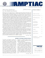
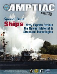
Edward LundquistMCR, LLCWith the growing use of integrated propulsion systems, smartgrids, and power electronics on ships, the venerable standard forelectrical installations on ships – IEEE-Std-45 – is being updated.New supporting standards are being developed to support bothmilitary and commercial ship designs.This task is a large one, and the chair of the IEEE-45 StandardCoordinating Committee, Moni Islam, says both new ideas andmore volunteers are needed to complete the mission. “In theprocess of standards development, we are initiating fundamentalsof design changing how we will design electrical systems in shipsin the future,” says Islam. Islam says he has an all-star team ofexperts to take on this very large task, but more qualified engineersare needed. “We want to encourage people to help with thiseffort,” Islam says.Islam says that those who come forward to work with the standarddevelopment team will join experts from the Navy, CoastGuard, American Bureau of Shipping (ABS), academia, andindustry. And, he says, they will be making a real contribution tothe profession. “All the team members have a say in the proposedstandard,” Islam says.Last revised in 2002, the longstanding standard needs to beupdated to allow for new methods of integrated power systemsand power electronics. Integrated Power Systems being installedaboard the new ships such as Navy’s new DDG 1000 and theRoyal Navy’s Type 45 destroyers feature installed power that isavailable for propulsion, sensors, weapons, and ship service. Sosophisticated power management systems are needed to managethose loads. If part of the system is knocked out, “graceful degradation”of the systems will ensure the most vital loads remain online. Graceful degradation offers reliability, and the use of matureand ruggedized commercial-off-the-shelf (COTS) based technologieswill result in total ownership cost savings.“We want to give this information in simple terms so thateverybody interested in fundamental ship design can contributeto supporting those changes,” Islam says.“We are involved in a new, emerging and rapidly changingtechnology. We are bringing an old technology – electric power –into a new world environment,” says Paul Bishop of the BishopGroup, who chairs the P45.3 Systems Integration and P45.4Mission Systems standards teams as well as the IEEE Power andEnergy Society’s Marine Systems Coordinating Committee. “Weare making things practical today that were not even consideredpossible just 10 years ago.”A large number of standards are currently under development,Bishop says. “These standards are establishing the rules for theelectric transfusion.”“IEEE 45 is the foundation for guiding an engineer in thedesign of a shipboard power system,” says Dr. <strong>No</strong>rbert Doerry, atechnical director at the Naval Sea Systems Command. “Powersystems onboard ships have evolved considerably over the recentAn artist’s rendering of the Zumwalt-class destroyer DDG 1000, a new class of multi-mission US Navy surface combatant ship designed tooperate as part of a joint maritime fleet, assisting Marine strike forces ashore as well as performing littoral, air and sub-surface warfare.(Photo courtesy of US Navy)The <strong>AMMTIAC</strong> <strong>WSTIAC</strong> <strong>Journal</strong>, <strong>Vol</strong>ume 1, Number 2 10http://ammtiac.alionscience.comhttp://wstiac.alionscience.com
past with the increased use of integrated power systems, powerelectronics, and advanced control systems. The traditional 60 Hz.AC450 volt 3 phase ungrounded distribution system is no longerthe favored option for many ship designs. The ongoing update ofIEEE 45 recognizes these changes have happened.”Islam explains the basic change is not complicated. “The traditional450-volt electrical system found onboard ships today isungrounded delta for low-voltage systems; and for medium-voltagesystems high resistance grounding is the common system. Thefundamental difference is that we will be making low and mediumvoltage the same. Low voltage systems will change to resistancegrounding.”The devil is in the details says Joe Piff, an electrical engineerwith MCR Federal who serves on the committee. “We can determinethat we need a standard plug to connect systems,” Piffsays. “But then we have to determine what colored wire goes towhat pin.”IEEE-45 will remain as the overarching standard for electricship design, but eight new “dot” standards have been approved.This progressive new standard will permit new electric-shipdesigns with Integrated Propulsion Systems (IPS). The IEEE-45standard was first released in 1920. To support the new IPSdesigns, the current update is looking at many issues that comeunder the standard, such as design, controls, integration, testingand others.Dennis K. Neitzel, CPE, IEEE Senior Member, director emeritusof the AVO Training Institute in Dallas, says that anyone whohas shipboard electrical experience should be involved with theeffort. “Input from those who know is vital to the usability of astandard.”Islam is looking to the research community to engage andaddress the offshore issues, provide data, and express the results ina form for practical applications. He is looking forward to Officeof Naval Research (ONR) sponsored <strong>Advanced</strong> Electrical PowerSystem (AEPS) engineers sharing the challenges they are facing toaddress protection coordination issues. “We need more work insystem protection coordination, and then it needs to be simplifiedto meet the guidelines expressed through the IEEE standards.This research must be done before it can be addressed at the standarddevelopment level,” Islam says.He is also looking to hear from the Variable Frequency Drive(VFD) manufacturers so they can share their issues related to thesystem-level protection challenges.“I appreciate the offshore industry personnel coming forwardwith issues which must be addressed by various communities,such as research entities, equipment manufacturers, and systemsof system designers,” he says.Individuals who would like to participate in this importanteffort to update IEEE-45 may contact:Moni IslamMoni.islam@ieee.org504-333-5004Captain Edward Lundquist, US Navy (Ret.) is a principal science writer for MCR Federal, LLC and has more than 27 years of publicaffairs, public relations, and corporate communications experience in military, private association, and corporate service. During his 24-yearnaval career, Mr. Lundquist qualified as a Surface Warfare Officer and later served as a Public Affairs Officer. He retired from active dutyin 2000. Lundquist currently is member of the executive committee for the Surface Navy Association, and serves as vice president of theGreater Washington Chapter. He is an Accredited Business Communicator (ABC) and the vice chair of the International Association ofBusiness Communicators Accreditation Council. Lundquist is a graduate of Marquette University in Milwaukee, Wisconsin and holds a master’sdegree in journalism and public affairs from the American University in Washington, DC. He writes frequently for publications includingArmed Forces <strong>Journal</strong>, Unmanned Systems, Naval Forces, Warships International, Maritime Reporter, and others.The <strong>AMMTIAC</strong> <strong>WSTIAC</strong> <strong>Journal</strong>, <strong>Vol</strong>ume 1, Number 2 11http://ammtiac.alionscience.comhttp://wstiac.alionscience.com
New Technical Resource for Scientists and Engineers:<strong>No</strong>ndestructive Testing Overview<strong>No</strong>ndestructive testing is a broadspectrum of analytical techniquesbased on physical principles,and it utilizes technicalaids ranging from theprimitive lenses to stateof-the-artimaging. Asequipment, machinery,and systems becomemore sophisticated anddependent on qualitycomponents, the field ofnondestructive testingbecomes increasingly vital.Although nondestructivetesting has been applied inone form or another for nearlya century, the field continues toadvance rapidly. TheAmerican Society for<strong>No</strong>ndestructiveTesting (ASNT)recently publishedtheThird Editionof its handbookthat presents anoverview of nondestructivetesting tocapture the latest advancementsin the rapidly changingfield. As <strong>Vol</strong>ume 10 in the<strong>No</strong>ndestructive Testing (NDT)Handbook Series, <strong>No</strong>ndestructiveTesting Overview strives to encapsulate the varioustechniques and technologies that constitute nondestructivetesting. It covers each NDT technique insufficient detail to serve as a useful technical referencefor the experienced testing engineer, but also presentsthe content in a manner that can help educate those notpreviously involved with nondestructive testing.The handbook provides a basic introduction to nondestructivetesting and an exhaustive bibliography ofhistorically significant works pertaining to nondestructivetesting.This 594 page reference book on nondestructive testingincludes – among several other topics – chapters onVisual Testing, Liquid Penetrant Testing, Leak Testing,Infrared and Thermal Testing, Radiographic Testing,Electromagnetic Testing, Magnetic Particle and FluxLeakage Testing, Ultrasonic Testing, Acoustic EmissionTesting, Vibration Analysis, Laser Testing, AlloyIdentification, and Strain Measure ment. A glossary isincluded to provide definitions and descriptions oftechnical terms associated with nondestructive testing.The development of the <strong>No</strong>ndestructive TestingOverview handbook was a collaborative effortwith contributions from experts that areworking in this field for academia, industry,and government organizations. The referencetherefore gives a comprehensiveoverview on the proven and potentialapplications of nondestructive testingtechniques. Detailed procedural informationas well as equipment and instrumentationcalibration methods is includedthroughout the book.The <strong>No</strong>ndestructive Testing Overview handbook,which was published in 2012, is currentlyavailable from ASNT. The reference can be purchasedin CD ROM and/or bound hardcover form fromwww.asnt.org.The <strong>AMMTIAC</strong> <strong>WSTIAC</strong> <strong>Journal</strong>, <strong>Vol</strong>ume 1, Number 2 12http://ammtiac.alionscience.comhttp://wstiac.alionscience.com
Jeffrey WidderChristopher PerhalaJames RascoeBattelle Memorial InstituteThis issue features a follow-up to Dr. Widder’s article on variable velocity, non-lethal ballistic weapons, which was published in <strong>Vol</strong>ume 1,Number 1 of the <strong>AMMTIAC</strong>-<strong>WSTIAC</strong> <strong>Journal</strong> (http://ammtiac.alionscience.com/pdf/AWJV1N1.pdf). The original article summarized theapproach to designing an improved non-lethal ballistic system and presented results from testing the new system. The follow-up article in thisissue presents more detail about the system parameters and design, including some of the variables and challenges that face designers of non-lethalballistic weapons. - EditorINTRODUCTIONThis terminal effects study was performed to identify design parametersfor the Battelle caseless, non-lethal projectile and identify therange of impact velocity needed for an escalation of force approach.At the low end of the force spectrum, the impact should cause ashort duration pain with no debilitating effect. At the upper end ofthe force spectrum, the level and duration of the pain should have adebilitating effect for several minutes to hours. In choosing appropriateimpact characteristics for a non-lethal blunt impact weapon,several things must be considered. First, what is the scenario for useand the desired outcome? For instance, one scenario for use is thata non-violent crowd is gathering, and there is risk that the crowdcould grow violent or become agitated due to the presence of instigators.In such a case, the desired outcome may be to prevent escalationand peacefully disperse the crowd; if the bull horn has failedto achieve this task, some level of force is needed.In general, it is best to use a minimal level of force such as teargas, flash bang grenades, and maybe soft-hitting kinetic rounds,such as the Battelle projectile fired to have a low impact velocity.The goal of this tactic is to reduce the number of individuals thewarfighter must confront by dispersing the “casual observers” andthose who do not wish any serious repercussions for themselves. Fora non-agitated crowd, this may be all that is required to get them todisperse; however, if some fraction of the crowd still resists, an additionalincrease in the level of discomfort may be needed to encouragecompliant behavior. At this point, it may be desirable to applya greater level of force to specific individuals that are leading thegroup. The Battelle non-lethal system has the accuracy and scalabilityto target individuals with successively harder hitting fires atranges up to and likely beyond 100 meters.There are two ranges for the increased level of impact that can beused; the first increased range of impact is a small escalation overtear gas and has a low risk of injury for impacts to the torso,abdomen, and extremities. This can be called the “paintball” level ofimpact and can be achieved with the Battelle non-lethal system byfiring in the reduced velocity mode when the range is less than 60meters, or at intermediate muzzle velocity when the range is greaterthan 60 meters. If the person is not wearing heavy clothing orThe <strong>AMMTIAC</strong> <strong>WSTIAC</strong> <strong>Journal</strong>, <strong>Vol</strong>ume 1, Number 2 13padding, the impact will produce a sharp, short duration pain thatwill likely deter less motivated individuals. Persons wearing heavyclothing or padding as a countermeasure will likely not be deterredby this level of impact; a higher level of impact is required.As the level of impact increases, the likelihood of the desiredcompliant behavior also increases, but so does the risk of producinginjuries that can be used by our adversaries to claim excessive forceand achieve a political success against us. It is important to understandwhat the risk of injury is as the impact velocity increases, andtake that into consideration as the level of applied force is increased.At an increased level of impact, simple countermeasures such aspadding can be defeated, and the weapon can be used to temporarilyincapacitate persons to aid in apprehension or disable and repelrock and Molotov cocktail-throwing individuals to ranges wherethey are ineffective. It is this level of impact that the Battelle nonlethalsystem is designed to produce when fired in the higher muzzlevelocity modes. At these higher levels of impact, the large variationin human tolerance to blunt impact and the risk of penetratinginjuries must be considered, particularly for the scenarios in whichthe appearance of excessive force can be counterproductive to overallmission goals.VARIABILITY IN HUMAN TOLERANCE – IMPACT ONNON-LETHAL WEAPONS USAGEThe primary performance goal for non-lethal blunt impact weaponsis that they transfer a sufficient amount of energy to the target tohave the desired effect, whether it is a moderate-to-high level of discomfortor some level of incapacitation that does not cause injuriesthat are permanent or that require medical treatment beyond simplefirst aid. Unlike lethal weapons that are designed to exceed thesethresholds, non-lethal weapons must have a terminal effect that isbetween two not very well defined thresholds. The lower thresholdis the level of discomfort required to produce a compliant behaviorby the target. The upper level is the threshold above which toosevere an injury occurs. Ensuring that the terminal effect of theweapon is between these two thresholds is compounded by the variabilityin human tolerance to blunt impact and pain as well asthings as simple as the thickness and weight of clothing worn.http://ammtiac.alionscience.comhttp://wstiac.alionscience.com
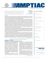
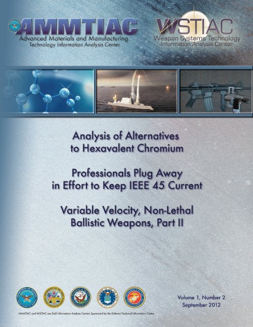
as the Blunt Criterion (BC) where BC = ln(E/(TDW 1/3 )) in which E is the kinetic energyin Joules of the projectile, T is the thickness incm of tissue under the point of impact, W is themass of the impacted person in kg, and D is thediameter of the projectile in cm. The followingrelationship can be used to estimate T,T=kW 1/3 , where k = 0.711 for males and 0.593for females. The BC has recently been reanalyzedand shown to have a linear relationship tothe Viscous Criterion (VC), 7 when the VC ismeasured for impacts with similar hard, flatnosedcylinders on fresh cadavers. The VC is avalidated method for predicting severity ofblunt trauma from an impact. The VC is anexperimentally measured term that relates themaximum in the product of the instantaneousvelocity of tissue or chest wall compression withthe degree of compression to the level of resultinginjury on the abbreviated injury scale (AIS).8 The relationship between VC and BC hasbeen shown by Bir and Vian to allow estimationof the AIS level of injury 9 from the calculatedBC as follows: AIS = 1.33BC + 0.60.The BC is a term calculated from knownprojectile parameters (i.e., mass, diameter,velocity) and from target properties (i.e.,weight and thickness of tissue) that can beassumed for given scenarios. This allows usto graphically show how changing the size ofthe person impacted either increases ordecreases the risk of blunt trauma injury. Italso allows investigation of how changes inmass, diameter, and striking velocity of theprojectile may influence the risk of injury,either increasing or decreasing it. Bearing inmind that the relationship of BC to AIS wasdeveloped with non-compliant flat-nosedcylinders, it likely overestimates the severityof injury when the impactor is of a compliantdesign or the impacted person is wearingheavy or padded clothing.SELECTION OF PROJECTILE PARAMETERSTo be effective against persons using heavyclothing and padding as a countermeasure,and to be effective at temporarily incapacitatinga person, the projectile needs to hit hardand produce significant instantaneous pain.To have an acceptably low risk of injury, theimpactor should produce a predicted AIS levelinjury for an impact to the thorax less than 2,the threshold for moderate injury. An AISLevel 1 injury will not require medical treatment,and AIS Level 2 may require medicaltreatment and certainly will have a longerperiod for full reversal to pre-engagement levelof capability.Battelle non-lethal ballistic system demonstrationat an indoor range. Green earplugs are off hand shots at 35 and 65yards, and the orange ear plugs are offhand,sitting shots taken from 100 yards.Battelle non-lethal ballistic systemdemonstration. A 10 shot group wasfired outdoors from the prone positionat 115 yards (one of the 10 shots hitbelow the target).If we assume that a kinetic energy densityof 30 J/cm 2 is the maximal permissible, basedon risk of penetration beyond tearing of subcutaneouslayers of fat and muscle (i.e., fullprojectile penetration), then we must pick aprojectile cross-section that keeps the totalkinetic energy of the round below thresholdsfor other severe injury. Skull fracture fromimpact with steel drop weights typicallyoccurs over a range of 33 to 75 ft-lbs, 10,11 andfracture of the facial bones has been observedin the automotive crash test studies to occurfrom 30 to 40 ft-lbs for the mandible andmaxilla and 4 to 10 ft-lbs for the zygomaticarch. A kinetic energy threshold below thatfor fracture of the zygomatic arch would resultin an ineffective blunt impact. However, akinetic energy threshold of 30 ft-lbs, which isbelow the fracture thresholds of the otherbones listed, can result in an effective blunttrauma impact.This is consistent with the historic, nonlethalanimal effects studies of the late 1970’sin which the US Army Human EngineeringLaboratories and the Swedish ResearchInstitute correlated the kinetic energy of aprojectile to injury sustained by impacted surrogateanimals. Recommendations to limitkinetic energy for non-lethal projectiles weremade based on their experimental results. TheHuman Engineering Laboratories describedprojectiles with energies below 30 ft-lbs (40.5J) as having a low probability of causing aninjury. Projectiles with energies between 30and 90 ft-lbs (40.5 and 121.5 J) were considereddangerous, and projectiles with energiesabove 90 ft-lbs (141.5 J) were likely to cause“severe damage.” 12Eye injury also must be considered, but likefracture of the zygomatic arch, it occurs atenergies far below what is effective as a bluntimpact. Stewart concluded that eye penetrationby small spheres occurred at an impactenergy density of 6 J/cm 2 plus or minus 1.5J/cm 2 . 13 It is likely any blunt impact weaponwill produce severe eye injury. Exampleswhere paintballs impacted the unprotectedeye have been recorded in many case studies,and impacts to surrogate pig eyes with paintballsat 300 ft/sec (91 m/sec) have been shownto cause rupture and shattering of the eyeglobe. 14If the kinetic energy of the Battelle projectileis limited to a maximum of 30 ft-lbs (40.5J) and a kinetic energy density of 30 J/cm 2 atimpact, the calculated diameter of the projectileis 1.31 cm (0.516 inch). Without anexemption from the Bureau of AlcoholThe <strong>AMMTIAC</strong> <strong>WSTIAC</strong> <strong>Journal</strong>, <strong>Vol</strong>ume 1, Number 2 15http://ammtiac.alionscience.comhttp://wstiac.alionscience.com
Tobacco Firearms and Explosives we are constrained to a projectileof 0.505 to 0.510 that can be fired through a .50 caliber barrel. Theprojectiles developed for the Battelle non-lethal system have a diameterof 0.506 inch which is 2% smaller than our calculated “ideal.”The mass of the presently designed and constructed Battelle projectilesis 8.7 grams. At a striking velocity of 320 ft/sec the projectilehas the maximum 30 ft-lbs of impact energy and an energy densityof 31 J/cm 2 which is 3% over the maximum identified above.The kinetic energy of the projectile described above at an impactvelocity of 320 ft/sec will have a low risk of causing skull fractureand fracture of the mandible and maxilla and low overall risk ofblunt trauma using the kinetic energy threshold mentioned above.Impact to the eyes and orbital bones will result in severe injury.Using the relationship between BC and AIS, given above, a predictionof the AIS level of injury for an impact to the thorax can bemade. For the Battelle projectile at the muzzle, the predicted AISlevel for a 50th percentile male is 1.8 which compares closely withsome of the bean bag rounds, also at the muzzle. The 12 gauge sockrounds impacting at 280 fps has calculated AIS of 1.7 if the sock isassumed to instantaneously open to a 2 inch diameter on impact.Lastly, we can use the models developed at the Edgewood Arsenalreferenced above to look at the risk of liver fracture from impacts tothe abdomen over the liver. The Edgewood Arsenal found experimentallythat if the value of MV 2 /WD < 414, where M is the massof the projectile in kg, V the impact velocity in m/sec, W the massof the impacted animal in kg, and D the diameter of the projectilein cm, none of the animals impacted exhibited liver fracture uponnecropsy. If the value was between 414 and 1,451, then 50% of theanimals exhibited liver fracture upon necropsy. When the value wasover 1,451, all the animals impacted exhibited liver fracture uponnecropsy. 6 The value for the 8.7 gram, Battelle projectile strikingwith a velocity of 320 ft/sec (97.5 m/sec) is 911, which puts this inthe middle of the range where liver fracture occurred in 50% of theimpacted animals. This is also comparable to most other non-lethalballistics which also fall within the 50% range. Since the EdgewoodArsenal did not identify the severity of the liver fracture, severityestimates cannot be predicted from this model. Small liver fractureswill heal without treatment, provided there are no other extenuatingor aggravating conditions.All free flying non-lethal ballistic projectiles have the greatest riskof causing a severe injury at the muzzle where the velocity of theprojectile is at a maximum. If the .50 caliber projectile is fired witha muzzle velocity of 320 ft/sec (97.5 m/sec), it will never exceedthresholds identified above. It will still be an effective blunt traumadeterrent at a range of 70 meters where the impact energy will havedropped to 68% of the 97 m/sec energy. If it is desirable to have alower risk of injury, the Battelle non-lethal system can be fired in alower velocity mode or the system can be designed to fire largerdiameter projectiles so that impact energy density and momentumdensity are lower for the same impact energy.By the use of tactics, techniques, and training, the risk of severeinjury can be decreased by targeting the heavy muscle groups of thelower extremities when circumstance permits or by firing at reducedmuzzle velocity. Further, by not targeting persons who are atincreased risk, specifically children, pregnant women, small-statureadults, the elderly and the malnourished, the risk of severe injury isfurther reduced.REFERENCES1 “<strong>No</strong>n-Lethal Human Effects Fact Sheet,” US Department of Defense <strong>No</strong>n-Lethal Weapons Program, http://jnlwp.defense.gov/pressroom/nlhe.html2 Sperrazza, J. and W. Kokinakis, “Ballistic Limits of Tissue and Clothing,”BRL TN 1645, January 1967.3 Lewis J.H., P.A. Coon, V.R. Clare, and L.M. Sturdivan, “An Empirical/Mathematical Model to Estimate the Probability of Skin Penetration byVarious Projectiles,” US Army Armament Research and DevelopmentCommand, Chemical Systems Laboratory Technical Report ARCSL-TR-78004, April 1978.4 DiMaio, V.J.M., A.R. Copeland, P.E. Besant-Matthews, L.A. Fletcher, A.Jones, “Minimal Velocities Necessary for Perforation of Skin by Air GunPellets and Bullets,” J. Forensic Sci. 27 (4), pp. 894-898, 1982.5 Bir, C.A., S.J. Stewart, and M. Wilhelm, “Skin Penetration Assessment ofLess Lethal Kinetic Energy Munitions,” J. Forensic Sci. 50 (6), pp. 1426-1429, 2005.6 Clare, V.R., A.P. Mickiewicz, J.H. Lewis, and L.M. Sturdivan, “BluntTrauma Data Correlation,” Edgewood Arsenal, May 1975, DTICDocument: ADA012761.7 Sturdivan, L.M., D.C. Viano, H.R. Champion, “Analysis of InjuryCriteria to Assess Chest and Abdominal Injury Risks in Blunt BallisticImpacts,” J. Trauma 56 pp. 651-663, 2004.8 Viano, D.C., and I.V. Lau, “A Viscous Tolerance Criterion for Soft TissueInjury Assessment,” J. Biomechanics, <strong>Vol</strong>. 21, <strong>No</strong>. 5, p. 387-399 (1988).9 Bir, C., and D.D. Viano, “Design and Injury Assessment Criteria forBlunt Ballistic Impacts,” J. Trauma, 57 pp. 1218-1224, 2004.10 Clemedson, C., G. Hellstrom, and S. Lindgren, “The Relative Toleranceof the Head, Thorax, and Abdomen to Blunt Trauma,” Annals New YorkAcademy of Sciences, <strong>Vol</strong>. 152, 1968.11 Schneider, D.C., and A.M. Nahum, “Impact Studies of Facial Bones andSkull,” Proceedings of the 16th Stapp Car Crash Conference, <strong>No</strong>vember 1972.12 Egner, D.O., “The Evaluation of Less-Lethal Weapons,” US ArmyHuman Engineering Laboratory Technical Memorandum 37-77,December 1977.13 Stewart, G.M., “Eye Protection Against Small High-Speed Missiles,”J.Ophth., 51, pp 51-80, 1961.14 Vinger, P., J.J. Sparks, K.R. Mussack, J. Dondero, and J.B. Jeffers, “AProgram to Prevent Eye Injuries in Paintball,” Sports Vision, pp. 33-40.Dr. Jeffrey Widder received his doctorate degree in chemistry from Duke University in 1993 for his research on modellithium electrodes. As a graduate student he developed a passion for metal working and machinery and produced much ofthe laboratory equipment used in his research. Upon completion of his degree, Dr. Widder accepted a research fellowshipthrough the National Research Council to do photo-acoustic spectroscopy of propellants undergoing pyrolysis at the ArmyResearch Laboratory (ARL), Aberdeen Proving Ground. While at ARL, Dr. Widder became involved in non-lethal ballisticsdevelopment and testing. In 1997 Dr. Widder accepted employment with Battelle Memorial Institute and was assignedto their Bel Air, Maryland, office. Troubled by previous problems with the performance of non-lethal ballistics, Dr. Widderconceived of a self-propelling projectile and built a prototype. Battelle provided Independent Research and Development(IR&D) funding to pursue a demonstrable launcher and ammunition. Dr. Widder refined the design of the projectile, set up a testing range, and amanufacturing capability to produce and assemble the projectile components and launchers used to test and demonstrate the systems.The <strong>AMMTIAC</strong> <strong>WSTIAC</strong> <strong>Journal</strong>, <strong>Vol</strong>ume 1, Number 2 16http://ammtiac.alionscience.comhttp://wstiac.alionscience.com
DirectoryCORE OPERATIONS MANAGERMary Priore201 Mill StreetRome, NY 13440315.339.7135; Fax: 315.337.9932Email: mpriore@alionscience.comDEFENSE TECHNICAL INFORMATION CENTERAttn: IAC Program Office (DTIC-I)8725 John J. Kingman Road, Ste 0944Ft. Belvoir, VA 22060-6218703.767.9120, Fax: 703.767.9119Email: iac@dtic.milURL: http://iac.dtic.mil/TECHNICAL INQUIRY SERVICES MANAGERChristian E. Grethlein201 Mill StreetRome, NY 13440-6916315.339.7009, Fax: 315.339.7107Email: cgrethlein@alionscience.com<strong>AMMTIAC</strong> & <strong>WSTIAC</strong> DIRECTORJohn L. Weed100 Valley Road, Ste 102Mount Arlington, NJ 07856973.770.0123, Fax: 973.770.1808Email: jweed@alionscience.comTRAINING COURSE COORDINATORGina Nash201 Mill StreetRome, NY 13440315.339.7047; Fax: 315.337.9932Email: gnash@alionscience.comFor a listing of upcoming materials, manufacturing & testing related events, please visit our website:http://ammtiac.alionscience.com/calendarFor a listing of upcoming weapon systems technology related events, please visit our website:http://wstiac.alionscience.com/calendar