Materials Challenges for the MEMS Revolution - Advanced ...
Materials Challenges for the MEMS Revolution - Advanced ...
Materials Challenges for the MEMS Revolution - Advanced ...
- No tags were found...

You also want an ePaper? Increase the reach of your titles
YUMPU automatically turns print PDFs into web optimized ePapers that Google loves.
AMPTIACA D VA N C E D M AT E R I A L S A N D P R O C E S S E S T E C H N O L O G YThe AMPTIAC News l et te r, Wi n ter 2001<strong>Materials</strong> <strong>Challenges</strong><strong>for</strong> <strong>the</strong> <strong>MEMS</strong> <strong>Revolution</strong>By Wade Babcock and David RoseReducing <strong>the</strong> size of an engineered system is a challenge often faced by designers and nowhere is thismore evident than in <strong>the</strong> field of electronics. The first digital computer known as <strong>the</strong> ElectronicNumerical Intergrator and Computer (ENIAC) was an enormous system constructed from over18,000 vacuum tubes, 1,500 relays, and hundreds of thousands of resistors, capacitors, and inductors.ENIAC weighed 30 tons and required 1800 ft 2 of floor space, all to provide a computationalcapability that was rapidly eclipsed by personal computers and even hand-held calculators.Soon after ENIAC was completed, researchers began to investigate ways to build computers withsmaller, faster, and more capable devices. Computer speeds increased markedly but <strong>the</strong>y were stilldependent upon components that were relatively large and bulky. The invention of <strong>the</strong> integratedcircuit and <strong>the</strong> utilization of lithography enabled numerous discrete devices to be combined andinterconnected with one ano<strong>the</strong>r on a single chip. These technologies also brought about true massproduction on a scale not seen be<strong>for</strong>e, dramatically lowering <strong>the</strong> unit cost of devices.Lithographic processes utilize a printed mask that locally protects <strong>the</strong> conductive top layer of <strong>the</strong>circuit board or device. The board or device with <strong>the</strong> mask applied to its surface is <strong>the</strong>n immersed inan acid that attacks and removes (etches) all surfaces not protected by <strong>the</strong> mask. The mask is laterremoved with a suitable solvent. The result of this etching process is a network of electrically conductivetraces that <strong>for</strong>m <strong>the</strong> circuitry <strong>for</strong>merly provided by wires. As a result, electronic equipmenthas generally became smaller and faster, and requires far less time to manufacture.Lithographic techniques have improved dramatically over <strong>the</strong> past <strong>for</strong>ty years. For instance, during<strong>the</strong> late 60’s, linewidths of 5 microns were being produced experimentally. Today’s linewidths areover 90% smaller, dramatically reducing <strong>the</strong> size of electronic devices. Additionally, many differenttypes of materials can be etched, not just <strong>the</strong> conductive top layer of a circuit board.Researchers now realize that <strong>the</strong> same processes used to fabricate electronic devices may also beemployed to miniaturize and mass produce mechanical systems. By integrating <strong>the</strong>se miniaturemechanical devices with existing electronic capabilities on <strong>the</strong> same chip, a new class of devicesknown as MicroElectroMechanical systems or <strong>MEMS</strong> is emerging.continues, page 2The pre<strong>for</strong>m is <strong>the</strong> backbone or skeleton of acomposite material. Because of this, many of<strong>the</strong> composite system’s properties are stronglyinfluenced, if not dictated, by <strong>the</strong> properties of<strong>the</strong> pre<strong>for</strong>m. Much of <strong>the</strong> cost associated with<strong>the</strong> production of a composite componentinvolves <strong>the</strong> pre<strong>for</strong>m’s raw material cost as wellas <strong>the</strong> labor required to manufacture <strong>the</strong> pre<strong>for</strong>m.A pre<strong>for</strong>m could be made of yarn orsingle fibers of fiberglass, aramid, carbon orceramic, with many configurations and variationsavailable. These options cover <strong>the</strong> spectrumof cost and per<strong>for</strong>mance from utilitarian,low cost applications to very specialized, highp e r<strong>for</strong>mance applications. The compositesindustry prides itself on being able to tailor <strong>the</strong>Spotlight on Technology: Composite Pre<strong>for</strong>msproperties of a component. Much of this tailorabilityis achieved by adjusting <strong>the</strong> variousparameters of <strong>the</strong> pre<strong>for</strong>m.The primary goal of tailoring per<strong>for</strong>mance isto maximize properties (usually mechanical)where <strong>the</strong>y need to be maximized and to allow<strong>for</strong> reduced properties where <strong>the</strong>y might not beas critical. To accomplish this, designers canadjust a multitude of pre<strong>for</strong>m pro p e rt i e s .Starting with <strong>the</strong> base fiber, going on to strandcharacteristics and weave design, a huge arrayof options are possible. As with most aspects ofcomponent manufacture, composite system ornot, <strong>the</strong> cost/per<strong>for</strong>mance ratio is <strong>the</strong> criticaldriver in deciding what pre<strong>for</strong>m technology touse.continues, page 7Volume 5, Number 1Spotlight on Technology … 1Ballistic Armor: An Overview … 9Biodegradable Lubricants … 12NAMIS … 15Dr. Paul MunafoNamed Manager … 16Standard ReferenceMaterial 2100 … 16John W. Lincoln Award … 16Calendar … 17Recent US Patents … 18AMPTIAC Directory … 19MaterialEASE 13Accelerated Degradationcenter insertAMPTIAC201 Mill StreetRome, New York 13440-6916P HON E: 315.3 39.71 17FAX: 315.3 39.71 07E M A I L: a mp t i a c @ i i t ri . o rgA M P T I AC is a DoD Info rmation Analysis Center Ad m i n i s te red by <strong>the</strong> Defense Info rmation Systems Ag e n c y, Defense Te chnical Info r mation Center and Opera ted by IIT Re s e a rch Inst i t u te
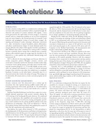
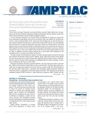
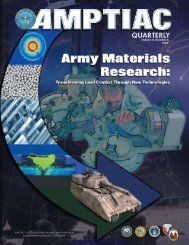
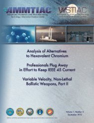
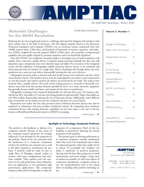
fabricated on silicon wafers. The evolution picked up steamin <strong>the</strong> late 80’s when <strong>the</strong> first simple spring-supported structureswere utilized as accelerometers. This application beganto reach fruition in <strong>the</strong> early 90’s when accelerometers fabricatedin conjunction with control circuitry were integratedon a chip and batch processed as airbag initiators <strong>for</strong> <strong>the</strong>automobile industry.Figure 2: SEM image of pressure-actuated lock from a prototype Navy safe and armingdevice. The long thin beam is a lever anchored in <strong>the</strong> background (upper left) and able tomove upward, out of plane in <strong>the</strong> <strong>for</strong>eground (lower right). Image courtesy of <strong>the</strong> WeaponsDepartment, Indian Head Division, Naval Surface Warfare Center.The current so-called “killer ap” (high growth potentialapplication) <strong>for</strong> <strong>MEMS</strong> appears to be <strong>the</strong> fiber optic switch.<strong>MEMS</strong> technology may be <strong>the</strong> best and most effective wayof switching fiber optic signals within <strong>the</strong> optical domain,eliminating <strong>the</strong> current need to convert optical signals toelectrical signals and back to optical in order to route networktraffic. This would allow increases in speed and bandwidthby eliminating <strong>the</strong> cumbersome and time-consumingprocess of converting and re-converting all signals numeroustimes during <strong>the</strong>ir journey.<strong>MEMS</strong> technology is finding its way into o<strong>the</strong>r areas outsideof your automobile and computer network. Military scientistsare working on devices to directly support <strong>the</strong>warfighter. Examples of <strong>the</strong> technologies being examinedinclude infrared, chemical, and biological agent sensors. Alsobeing considered are MEMs <strong>for</strong> GPS mapping, radio telemetry<strong>for</strong> identify-friend-or-foe (IFF), and smart weapons. Anef<strong>for</strong>t is currently underway to develop <strong>the</strong> capability to generatepower from a very tiny package. DARPA is fundingwork on a postage-stamp sized gas turbine intended to generateas much as 50 Watts of electricity <strong>for</strong> a week to powerall <strong>the</strong> electronic gear that <strong>the</strong> future soldier will carry intobattle.The military services are also working on applying <strong>MEMS</strong>technology to <strong>the</strong> fuzing and safeing devices integrated intotomorrow’s weaponry. In Figure 2, a prototype <strong>MEMS</strong> safeand arming device is shown. A diaphragm is etched into <strong>the</strong>underside of <strong>the</strong> silicon wafer, allowing pressure to push <strong>the</strong>diaphragm and lever upward to disengage a lock. The deviceis one of seven <strong>MEMS</strong> technologies that <strong>the</strong> Naval SurfaceWarfare Center, Indian Head Division is integrating onto asingle-chip <strong>MEMS</strong> safe and arming device. Smaller electronicsystems allow more volume in existing weapons <strong>for</strong> energetics(both fuel and explosives). Next generation systemsincorporating improved guidance and control circ u i t ry,smaller fuzing, and enhanced energetic solutions, will besmaller overall meaning that launch plat<strong>for</strong>ms may carrymore ordnance or more kinds of ordnance systems toi m p rove multi-mission deployment capability. Im p rove delectronics will assure that pinpoint accuracy and precisionwill allow weaponry to be smaller but just as, if not more,effective.<strong>MEMS</strong> may also enable better inventory control by allowingsensors to be imbedded in all types of equipment toaccount <strong>for</strong> degradation and aging of components.Additionally, inexpensive imbedded sensors may enable <strong>the</strong>range of ballistic projectile weapons to be better controlled“on-<strong>the</strong>-fly” by providing barrel and energetic material temperaturein<strong>for</strong>mation to a fire control system <strong>the</strong> momentthat a round is loaded into a weapon. This way, <strong>the</strong> fire controlsystem could account <strong>for</strong> expansion of gun barrels (dueto heating during rapid firing) and adjust trajectories accordingto predicted per<strong>for</strong>mance of <strong>the</strong> round.In <strong>the</strong> medical sciences, <strong>MEMS</strong> may provide portable, lowcost, hand-held tools that will be able to sample and analyzetissue or blood samples quickly. There also exists <strong>the</strong> capabilitythat sensors or actuators could be implanted in <strong>the</strong> bodyto send telemetry or stimulate tissue when queried by externalsystems. For a diabetic, this could allow an implantedFigure 3: Spring supported structure utilized <strong>for</strong> testing <strong>the</strong> elastic responseof <strong>MEMS</strong> structures. For reference, <strong>the</strong> springs are about 100 microns tall and30 microns thick. Image courtesy of <strong>the</strong> Weapons Department, Indian HeadDivision, Naval Surface Warfare Center.device to monitor blood sugar levels and react on that data.O<strong>the</strong>r possibilities include systems that could send signals tomuscle-stimulation implants, giving paralyzed victims limitedmuscle control. <strong>MEMS</strong> also show promise as sensingdevices to monitor exposure to potential chemical or biologicalagents during wartime.In addition to <strong>the</strong> above applications, <strong>MEMS</strong> devicesmust also be developed to test and verify <strong>the</strong> response of<strong>MEMS</strong> components. Figure 3 shows a device used to test <strong>the</strong>continues, page 4The AMPTIAC Newsletter, Volume 5, Number 1 3
elastic response of <strong>MEMS</strong> structures. Here <strong>the</strong> beam visiblein <strong>the</strong> center of <strong>the</strong> structure is free to move in-planeand is supported about 4 microns off <strong>the</strong> wafer’s surface byfour folded springs.<strong>Materials</strong> <strong>Challenges</strong>Of concern to <strong>the</strong> materials community is <strong>the</strong> simple factthat <strong>MEMS</strong> devices must do mechanical things. Microstructureslike springs, actuators, guides, gears, axles andstops behave and interact with one ano<strong>the</strong>r in unique ways.The fundamental problem is <strong>the</strong>se structures are fabricatedusing <strong>the</strong> materials and processes originally developed <strong>for</strong>electronic devices. As such, <strong>the</strong> knowledge base on howelectronic materials behave when used <strong>for</strong> micromechanicalapplications is limited. Only recently has <strong>the</strong> communitybegun to study <strong>the</strong> necessary mechanical propertiesneeded to mature <strong>MEMS</strong> applications.Micro <strong>Materials</strong> Issues in <strong>MEMS</strong><strong>Materials</strong> CharacterizationThe materials routinely used to fabricate <strong>MEMS</strong> devicesare <strong>the</strong> same ones developed <strong>for</strong> use in <strong>the</strong> manufacture ofintegrated circuits. In fact, most of <strong>the</strong> organizations making<strong>MEMS</strong> are using <strong>the</strong> “obsolete” 100mm wafer equipmentthat companies like Motorola, Texas Instruments,Intel and o<strong>the</strong>rs have surplused to upgrade to 150 and200mm wafer equipment. This is not meant to imply that<strong>the</strong> equipment is sub-par in any way, just to emphasize that<strong>the</strong> fabrication techniques and materials used are indeed“hand-me-downs” from <strong>the</strong> IC industry.In <strong>the</strong> last thirty years, much work has been done tocharacterize <strong>the</strong> electrical and <strong>the</strong>rmal properties of electronicmaterials, and how <strong>the</strong>se properties interact to makereliable electrical components. Since electronic devices donot have mechanical functions, <strong>the</strong> materials used to construct<strong>the</strong>m were not well characterized at <strong>the</strong> micro-level.Now that <strong>the</strong>se materials are being used to make beams,springs, gears, or wear surfaces, <strong>the</strong> knowledge base of processing-dependentmechanical properties must be developed.As a result, <strong>the</strong> materials in question are being reexaminedto develop <strong>the</strong> data necessary to address <strong>the</strong>needs of design engineers. This work is still very much in<strong>the</strong> early stages.Macro vs. Micro <strong>Materials</strong> PropertiesResearchers have discovered that material properties measuredat <strong>the</strong> scale of <strong>MEMS</strong> are not necessarily equal to <strong>the</strong>properties measured <strong>for</strong> <strong>the</strong> same bulk, macro-scale materials.For instance, <strong>the</strong> Young’s Modulus of bulk nickel hasbeen measured as 207 GPa. But measurements of Young’sModulus <strong>for</strong> various nickel structures fabricated by depositionand micromachining techniques range from 150 toabout 200 GPa. This discrepancy could have drastic effectsif an engineer designs a structure in a critical device torespond to input based on <strong>the</strong> macroscopically measuredmodulus, and <strong>the</strong> structure responds in an unexpected way.Many devices are fabricated from single crystal silicon,poly-crystalline silicon (polysilicon) or thin-film, polycrystallinemetals such as aluminum, titanium, nickel andsome ferrous alloys. The mechanical properties are obviouslywell understood and characterized <strong>for</strong> single crystalsilicon, even accounting <strong>for</strong> properties dependent on crystallographicdirections. Poly-crystalline materials behave ina very different manner and <strong>the</strong>ir mechanical properties areusually dependent on <strong>the</strong>ir processing history.Some of <strong>the</strong> legacy techniques used to deposit uni<strong>for</strong>mlayers of polymers, insulators (nitrides or oxides of silicon)or metals include epitaxy, sputtering, chemical vapor deposition,evaporation, spin-on methods and electroplating.All of <strong>the</strong>se present unique material challenges and opportunitiesto fine-tune various aspects of material properties.Some create radially dependent microstructures, o<strong>the</strong>rsyield columnar or spherical microstructures. The net effectis that a material that would normally possess isotropicproperties at <strong>the</strong> macroscopic scale may indeed have localizedprocessing-related anisotropic properties.Understanding intrinsic material properties at <strong>the</strong> microscale is only part of <strong>the</strong> problem. <strong>MEMS</strong> fabrication techniquesoften utilize plasma or wet-chemical etching toremove unwanted material. These processes can lead tosurface imperfections due to damage or contaminationfrom <strong>the</strong> etchants.Grain SizeThe dimensions of some structures are often within <strong>the</strong>same order of magnitude as <strong>the</strong> crystal grain size of <strong>the</strong>material used to fabricate it. For example, typical grainsizes <strong>for</strong> an electroplated nickel will be about 0.5 to 2microns and a spring found on a <strong>MEMS</strong> device may beabout 20 to 30 microns across at its smallest dimension.That spring may have only 10 to 20 grains across its width.Classical assumptions regarding grain boundaries and<strong>the</strong>ir effects on mechanical properties may not hold at <strong>the</strong>microscale. Just consider <strong>the</strong> possibility that <strong>the</strong> height of acolumnar grain might be 1/2 to 3/4 <strong>the</strong> total thickness ofa deposited film. How this effects <strong>the</strong> structural stiffness oryield behavior of a structure fabricated in that film is notreadily understood.Properties Depend on ProcessingProcessing history, which evolves specific microstructuralcharacteristics, will have impact on <strong>the</strong> resultant physicalproperties of <strong>the</strong> material. Much of <strong>the</strong> field of materialsscience is based on <strong>the</strong> study of <strong>the</strong> processing-propertyrelationship. In <strong>MEMS</strong>, <strong>the</strong> processing techniques ofteninvolve exposure to temperature variations, chemical baths,gaseous chemicals, ultra-violet light and in some cases x-ray radiation. Incorporation of impurities into <strong>the</strong> materialsduring processing can modify <strong>the</strong>ir mechanical properties.With a thorough knowledge of <strong>the</strong> processing-propertieslink, this aspect may be used to <strong>the</strong> advantage of <strong>the</strong>resulting devices.Property Dependence on Storage/Environmental ExposureAgain, <strong>the</strong> materials heritage in <strong>MEMS</strong> is a legacy from <strong>the</strong>IC industry and <strong>the</strong> countless hours of research and developmentover <strong>the</strong> last four decades to tailor those materialsto stand up to <strong>the</strong> rigors of <strong>the</strong> electrical environment. Thecontinues, page 6<strong>Materials</strong><strong>Challenges</strong><strong>for</strong> <strong>the</strong><strong>MEMS</strong><strong>Revolution</strong>continuedfrompage 34The AMPTIAC Newsletter, Volume 5, Number 1
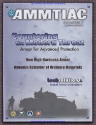
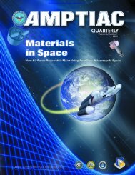
How to Make a <strong>MEMS</strong> Structure: The Oversimplified VersionStart with a silicon wafer. These are typically about 300 to 400 microns thick (that’s 0.3 to 0.4 mm.)The silicon wafer is <strong>the</strong>n heated and reacted with a nitrogen-rich gas such that its surface gets a thinlayer of silicon nitride, typically less than one micron thick.The silicon nitride layer is <strong>the</strong>n patterned.There are various ways of accomplishing this and <strong>for</strong> our purposes a simple example is used. Aphotoresist is applied over <strong>the</strong> entire surface. The resist is <strong>the</strong>n exposed to radiation, typically UV,which causes it to become more soluble to an etchant in <strong>the</strong> exposed areas than in <strong>the</strong> unexposedareas. (This is said to be a “positive” resist; if <strong>the</strong> resist becomes less soluble upon exposure it iscalled a “negative” resist.) The wafer is <strong>the</strong>n etched with a solvent and <strong>the</strong> areas of resist that wereexposed are removed. Then <strong>the</strong> wafer is etched with a solvent that will attack <strong>the</strong> silicon nitride. Butonly <strong>the</strong> areas that are exposed, most of it is under a coating of resist. Then <strong>the</strong> remaining photoresistis removed with some o<strong>the</strong>r etchant, leaving behind a patterned silicon nitride layer.In all cases, materials and solvents are chosen specifically so that <strong>the</strong> solvent etches a specificmaterial much faster than it attacks any of <strong>the</strong> o<strong>the</strong>r materials. In fact, most of <strong>the</strong> materials are chosenbecause <strong>the</strong>y etch much faster (>10 times) in one direction than <strong>the</strong>y do in any o<strong>the</strong>r.A sacrificial layer is applied to <strong>the</strong> entire surface. These are chosen specifically to fill all areas and<strong>for</strong>m a smooth surface.The sacrificial layer is <strong>the</strong>n patterned through an etching process very similar to that discussedabove.Now a structural material is applied. The material varies from process to process; sometimes it ispolycrystalline silicon, o<strong>the</strong>r times it is a thin polymer. And <strong>the</strong> thickness varies depending on devicebeing made. Typical devices are ei<strong>the</strong>r a few microns thick or about 30 to 80 microns thick.The structural layer is patterned, once again using an etching process similar to that describedpreviously.The entire sacrificial layer is etched away.As a final step, a solvent is used that will etch <strong>the</strong> silicon wafer where it is exposed under <strong>the</strong> beam.The sidewalls of <strong>the</strong> etch pit are sloped because <strong>the</strong> wafer is a single crystal of silicon and it etchespreferentially down crystal faces. The depth of <strong>the</strong> pit is controlled ei<strong>the</strong>r by etching <strong>for</strong> a specificperiod of time (silicon etch rates are well documented in various solvents <strong>for</strong> almost any temperature,)or by allowing <strong>the</strong> etch to continue until <strong>the</strong> sidewalls meet.The finished product, a singly supported beam. Or a <strong>MEMS</strong> diving board, over a very small pool.The AMPTIAC Newsletter, Volume 5, Number 1 5
challenge in <strong>MEMS</strong> is to fur<strong>the</strong>r characterize <strong>the</strong> effects ofstorage and exposure on mechanical devices at this scale.Some of <strong>the</strong> questions that arise are:• Do <strong>the</strong> classical mechanics of annealing, recrystallizationand grain growth apply at this scale?• Will kinetic processes involving impurities (both intendedand unintended) be changed by <strong>the</strong> relative proximityof exposed surfaces in some of <strong>the</strong> very small structures?• Are contaminants from <strong>the</strong> environment more or lessaggressive due to increased free surface areas on <strong>the</strong> verytiny structures?Concerns over FrictionOne technology that has seen significant friction-relatedresearch over <strong>the</strong> past 20 years is development of <strong>the</strong> computerhard drive. This device requires a read-write head toskim about 50 nanometers (millionths of a meter) over aspinning disk and “skid” to a soft landing each time <strong>the</strong>disk comes to a stop. The sliding action during spin-upand spin-down have been <strong>the</strong> subject of millions of dollarsin micro- and nanotribological research over <strong>the</strong> past fewdecades. This technology represents a multi-billion dollarper year industry, so it is no wonder <strong>the</strong> investment in itsimprovement has been so great.Now <strong>the</strong> study of friction, or tribology, on <strong>the</strong> microandnano-scale has extended into <strong>the</strong> arena of <strong>MEMS</strong>devices and materials. As one can see, when a relativelynew engineering technology comes along with <strong>the</strong> capabilityto produce machines with gears, sliding contactsand rotors, all on a micro scale, it would follow that awhole new lubrication technology should be considered.When confronted with <strong>the</strong> materials and devices beingfabricated, some of <strong>the</strong> nation’s most respected researchersin <strong>the</strong> fields of micro- and nanotribology differ in <strong>the</strong>irbasic opinions on what is “good” and what is “bad” interms of friction <strong>for</strong> machines. Just <strong>the</strong> case of electroplatednickel being used as a structural material sparks controversywhen one brings up <strong>the</strong> issue of sealing a devicefrom humidity. Some say humidity will cause very highinterfacial friction between nickel parts, o<strong>the</strong>rs believethat it would lubricate (or possibly passivate) <strong>the</strong> interface,lessening friction.Current commercial <strong>MEMS</strong> devices are mostly noncontactlight-signal interrupters or accelerometers. Butapplications <strong>for</strong> mirror devices that rotate or “tip” fromside to side (in fiber optic signal routers or display paneltechnology) are beginning to see demand. Friction, stiction(<strong>the</strong> tendency of very small parts to stick toge<strong>the</strong>rthrough something similar to electro-static attraction) andwear will soon become very important issues to <strong>the</strong> micromaterialscommunity.Conclusions<strong>MEMS</strong> devices have <strong>the</strong> potential to revolutionize <strong>the</strong> waywe currently do many things. Building upon <strong>the</strong> legacy ofelectronic device miniaturization and cost reduction, westand upon <strong>the</strong> cusp of an explosion in new applications<strong>for</strong> <strong>MEMS</strong> technologies. However, much work remains.The variation of material properties away from acceptedvalues at <strong>the</strong> scale of <strong>MEMS</strong> devices is one of <strong>the</strong> fundamentalproblems to be understood. Fabricating waferscale,thin materials that may have anisotropic behaviorand <strong>the</strong>n employing micromachining techniques to fashionmechanical devices results in unknowns that couldimpact device per<strong>for</strong>mance. Also, issues related to frictionand stiction of micro- and nano-scale materials must beaddressed fully.It is clear that more research is necessary to address <strong>the</strong>problems now faced by <strong>MEMS</strong> designers. However, <strong>the</strong>investments needed to fully characterize <strong>the</strong> per<strong>for</strong>manceand behavior of materials used <strong>for</strong> <strong>MEMS</strong> are warranted.Fur<strong>the</strong>r maturation of <strong>the</strong>se processing technologies anddevelopment of <strong>the</strong> associated materials knowledge willenable accurate and predictable device per<strong>for</strong>mance. Thisin turn will allow future applications that could have adramatic and profound influence on many facets of life. ■<strong>Materials</strong><strong>Challenges</strong><strong>for</strong> <strong>the</strong><strong>MEMS</strong><strong>Revolution</strong>continuedfrompage 4AMPTIAC Mailing List Updates WantedThe AMPTIAC Newsletter is currently mailed to over 23,000 customers. It is our policy to provide a free subscription toanyone who has a use <strong>for</strong> it, and to refrain from sending copies to anyone who does not want or cannot use <strong>the</strong> publication.To keep our mailing list current, we need <strong>the</strong> help of our readers. If any of <strong>the</strong> following situations apply, pleaselet us hear from you:• If you are reading a borrowed copy and would like your own free subscription, please ask <strong>for</strong> one.• If you receive <strong>the</strong> newsletter and have no use <strong>for</strong> it, please request removal from our list of subscribers.• If you are getting a copy under <strong>the</strong> wrong name or wrong address, please provide a correction.Your help in keeping our records current will be greatly appreciated. Additions, deletions and corrections may besent by e-mail to amptiac@iitri.org, telephoned to (315) 339-7092, faxed to (315) 339-7107, or mailed to AMPTIAC,201 Mill Street, Rome, NY 13440-6916. ■6The AMPTIAC Newsletter, Volume 5, Number 1
Biodegradable LubricantsThroughout <strong>the</strong> industrial age, natural resources have beenturned into products that are no longer recognizable by <strong>the</strong>microorganisms and enzymes that convert <strong>the</strong>se substances in<strong>the</strong>ir natural state into <strong>the</strong>ir basic building blocks. For example,oil degrades when it exists in its original state but becomes hazardousonce turned into different compounds.“Degradable” entails <strong>the</strong> decomposition of a product into itsbasic components by any means. “Biodegradable” more specifically,is decomposition through biological means, and <strong>the</strong> disappearanceinto <strong>the</strong> environment without harmful effects. However,disposal of biodegradable products must be done correctly inorder <strong>for</strong> its components to properly decompose. It is importantto note that a product’s active ingredients are biodegradable while<strong>the</strong> inactive ingredients are not. The Federal Toxic SubstancesControl Act defines biodegradability as <strong>the</strong> breakdown of organiccompounds, both natural and syn<strong>the</strong>tic, to carbon dioxide,water, <strong>the</strong> oxides or mineral salts of o<strong>the</strong>r elements as well asproducts associated with normal metabolic processes of microorganisms.Scientific Certification Systems (SCS) defines as“biodegradable” only <strong>the</strong> products that are entirely biodegradableunder aerobic and anaerobic conditions, into carbon dioxide,w a t e r, and minerals. Products considered “c o m p o s t a b l e ,”although similar to “biodegradable,” undergo natural degradationof <strong>the</strong>ir solid materials only.[1]The Resource Conservation and Recovery Act (RCRA) establishedfederal authority, through <strong>the</strong> Environmental ProtectionAgency, to control hazardous waste from “cradle to grave.” Thisincludes <strong>the</strong> generation, transportation, treatment, storage anddisposal of hazardous waste. On September 14, 1998, ExecutiveOrder 13101, “Greening <strong>the</strong> Government through Wa s t ePrevention, Recycling, and Federal Acquisition”, was signed. ThisExecutive Order is currently directing federal agencies to procurerecycled and environmentally friendly products. The DoD-issuedHazardous Waste Minimization (HAZMIN) and RCRA policiesare mandating that all DoD installations must reduce <strong>the</strong> amountof toxicity and hazardous waste generated by petroleum oil lubricant(POL) products whenever it is economically viable.[2]The US Department of Defense has used jeeps, trucks, selfpropelledartillery, bulldozers, mobile bridges, watercraft, ships,submarines, cranes, planes and tanks <strong>for</strong> decades. All <strong>the</strong>se vehicleshave caused contamination due to petroleum and its relatedproducts – gasoline, diesel fuel, aviation fuel, lubricating oils andgreases – from accidental spills, improper storage of fluids, malfunctioningof equipment, failure of components, etc.[3] As aresult, <strong>the</strong> Defense Supply Center in Richmond, Virginia, whichdistributes packaged petroleum, oil and lubricant products <strong>for</strong> <strong>the</strong>Defense Department, has ga<strong>the</strong>red data on industrially availablefluids and generated a catalog <strong>for</strong> environmentally safe products.“FY 99 Environmental Products Catalog” is <strong>the</strong> latest edition.Biodegradation StandardsASTM Standard D 5864-95 is a standard method <strong>for</strong> determiningaerobic aquatic biodegradation of lubricants or <strong>the</strong>ir components.ASTM defines biodegradation as “The process of chemicalbreakdown or trans<strong>for</strong>mation of a material caused by organismsor <strong>the</strong>ir enzymes.” Accordingly,Lubricant + O 2 + Microorganisms → CO 2 +H 2 O + More MicroorganismsASTM biodegradation testing identifies two types of test regimes:• The primary test measures only <strong>the</strong> disappearance of <strong>the</strong> originalmaterial and includes chemical changes detected by measurableproperties such as variations in <strong>the</strong> infrared (IR) band.• The ultimate test measures <strong>the</strong> percent of <strong>the</strong> material convertedto carbon dioxide and water. The oxidation of <strong>the</strong> lubricantis directly measurable through <strong>the</strong> evolution of CO 2 (or consumptionof O 2 ).The United States Air Force definition of biodegradability dividesbiodegradable materials into four classes, according to <strong>the</strong> timerequired <strong>for</strong> complete biodegradation:• Class I – 60% degradation after 28 days of testing• Class II – 40% in 28 days and 60% in 84 days• Class II – 40% in 84 days• Class IV – none of <strong>the</strong> above[4]DoD Ef<strong>for</strong>ts in BiodegradationThe US Navy is seeking a biodegradable fluid that is compatiblewith existing fluids, prevents corrosion due to seawater, andpreferably does not leave a sheen on <strong>the</strong> water. The Navy is alsoconcerned about possible pollution hazard from lubricants andhydraulic fluids from machinery that is susceptible to release of oiloverboard through seawater wash off, incidental leakage due todamaged seals, or discharges from failed equipment. T h ePollution Prevention and Material Safety Branch of <strong>the</strong> Navy isassessing commercially available lubricants and hydraulic fluidsthat can replace <strong>the</strong> conventional petroleum products. Theseproducts, also entitled “environmentally preferable lubricants”(EPLs), are usually made from vegetable oils such as rapeseed,corn, sunflower or soybean oil, syn<strong>the</strong>tic esters, polyalkylene glycols(PAGs), or severely hydrotreated petroleum based oils. EPLsvary in <strong>the</strong>ir per<strong>for</strong>mance. For example, vegetable oil-based fluidshave good lubricity and <strong>the</strong>ir viscosity is less dependant on temperaturethan <strong>the</strong> petroleum oils; never<strong>the</strong>less, <strong>the</strong>y freeze at temperatureson <strong>the</strong> order of -15°C and begin to degrade at temperaturesabove 90°C. Syn<strong>the</strong>tic esters are more stable and can operatewithin a wide range of temperatures. Current fluids used aswire rope lubricants (MIL-G-18458) are petroleum-based, containlead and in one case, asphalt. Certain EPLs have been identifiedfrom a database of commercially available lubricants, builtby <strong>the</strong> Navy’s Pollution Prevention and Material Safety Branch asreplacement candidates <strong>for</strong> <strong>the</strong>se lubricants. The products exceedingper<strong>for</strong>mance criteria <strong>for</strong> corrosion protection, lubrication andstability will be tested by <strong>the</strong> ultimate type standard ASTM aquaticbiodegradation and toxicity tests.[5]The Fuels and Lubricants Technology Team of <strong>the</strong> Army Ta n k -Au t o m o t i ve Re s e a rch, De velopment, and Engineering Centers(TARDEC) is developing two parallel programs: (1) hyd r a u l i cfluid re c ycling, and (2) development of environmentally safeh ydraulic fluids and greases. Ac c o rd i n g l y, <strong>the</strong> Army is using inaddition to ASTM D5864-95 method, a recently deve l o p e dASTM test called St a n d a rd Classification <strong>for</strong> Hydraulic Fluids <strong>for</strong>En v i ronmental Impact (ASTM D6046-98a). These test methodswe re developed by <strong>the</strong> ASTM D-12 Subcommittee onEn v i ronmental St a n d a rd of Lubricants. This organization hasd e veloped new biodegradation test methods based on acute tox i c-ity tests established by <strong>the</strong> Organization <strong>for</strong> Economic Co-12The AMPTIAC Newsletter, Volume 5, Number 1
Operation and De velopment (OECD). The Army initiallyfocused on hydraulic fluids, <strong>the</strong> rationale being that <strong>the</strong> technologywould be applicable also to grease. Twenty-six biodegradablefluids, mostly designated as industrial hydraulic fluids, we re studiedand evaluated against MIL-H-46001, <strong>the</strong> military’s own industrialfluid specification.[3] The re q u i rement <strong>for</strong> biodegradablefluids that could function within military specs, made it necessaryto put toge<strong>the</strong>r additional evaluations against MIL-PRF-6083 andMIL-H-46170, two military hydraulic fluids used in tanks ando<strong>the</strong>r armored vehicles and equipment. The initial re q u i re m e n t simposed on biodegradable hydraulic fluids included:• A wide temperature range (-54°C to 125°C)• Ability to protect against wear, corrosion, and cope withheavy weight• Compatibility with elastomers• High temperature oxidation stability• Low volatility• High biodegradability.These preliminary tests resulted in <strong>the</strong> <strong>for</strong>mulationof 11 fluids that were tested against rigorousmilitary specifications. Five hydraulic fluids, four of<strong>the</strong>m being vegetable fluids such as rapeseed andsoybean, and one of <strong>the</strong>m a syn<strong>the</strong>tic polyester type,were ultimately selected <strong>for</strong> field demonstration,based on <strong>the</strong>ir per<strong>for</strong>mance in laboratory testing.The next step – <strong>for</strong>mulation of biodegradablelubricating greases or BLGs <strong>for</strong> <strong>the</strong> Army – proved a much hardertask. An Army biodegradable grease has to per<strong>for</strong>m in accordancewith MIL-G-10924F Grease, Automotive and Artillery(also known as “GAA”), a grease required <strong>for</strong> all Army groundvehicles and equipment. It is important to note that GAA hasbeen replaced by MIL-PRF-10924G, which carries <strong>the</strong> new designation<strong>for</strong> specification purposes.Major problems with <strong>the</strong> development of BLG products stemfrom <strong>the</strong> lack of criteria that would accurately define biodegradabilityand lubrication properties. Also, <strong>the</strong> difficulty with liquefyinggreases impedes <strong>the</strong> re-cycling of <strong>the</strong>se materials. For thatreason, most military greases do not meet <strong>the</strong> DoD HAZMINgoals. Extensive research to generate greases with quantifiablebiodegradability and lubrication properties has been conducted asa result of new DoD requirements.[6][7][8]The original MIL-G-10924 greases consist of a blend of 65%in weight Polyalphaolefin (PAO), 10% petroleum oil, 15% oflithium-complex thickener, and 10% additives. MIL-G-10924greases can operate within a wide temperature range (-54°C to180°C), have excellent water, storage, shear and oxidation stability,possess good anti-wear and load-carrying capacity, and offeradequate saltwater corrosion protection, but have low biodegradability.[2]Table 1 tabulates <strong>the</strong> three BLGs that were <strong>for</strong>mulatedwith a grease manufacturer. BLG-1 and BLG-2 were <strong>for</strong>mulatedon <strong>the</strong> basis of <strong>the</strong> nonbiodegradable MIL-G-10924F grease specifications,while BLG-3 has been produced from a low viscosityblend of ester oils. Each grease contained 15% lithium complexthickener and 10% o<strong>the</strong>r additives.Examination of biodegradability <strong>for</strong> <strong>the</strong> three BLGs, using MIL-G-10924F as a base grease shows that <strong>the</strong> 28 days biodegradabilitya c c o rding to OECD Modified Sturn Test (that defines biodegradationas <strong>the</strong> maximum carbon conversion or carbon dioxide generationunder we l l - c o n t rolled conditions <strong>for</strong> a period of 28 days)ranges from 28% <strong>for</strong> MIL-G-10924F grease to 64% <strong>for</strong> BLG - 3 .The test results indicate that a small amount of biodegradabilityi m p rover (in this case, rapeseed oil) may significantly improve <strong>the</strong>biodegradability of <strong>the</strong> lubricating grease. This is attributable to <strong>the</strong>fact that bacteria like to eat natural ester flavo r.Military greases, as a whole, are designed <strong>for</strong> open lubricationsystems such as automobile wheel bearings, chassis systems, gearboxes,etc. Experimental BLG greases considered by <strong>the</strong> Armyhave to respond to <strong>the</strong> a<strong>for</strong>esaid applications. Table 2 tabulates<strong>the</strong> test protocols and data obtained from testing per<strong>for</strong>mancecharacteristics of BLG.So far, results indicate that hydraulic fluids and greases can satisfyenvironmental requirements and meet military specifications.Due to initial success in tests of biodegradable replacements <strong>for</strong>current fluids such as GAA greases and MIL-H-46170 (FRH)Composition* MIL-G-10924F BLG-1 BLG-2 BLG-3Base oil 75% PAO + 65% PAO 55% PAO 75% Polyol ester +MineralDiester + PAOBiodegradation None 10% 20% Noneimprover(rapeseed oil)*All compositions contain 15% lithium complex thickener and 10% o<strong>the</strong>r additivesTable 1: Experimental biodegradable lubricating greases (BLG)[2]hydraulics, military per<strong>for</strong>mance specifications will be developedin <strong>the</strong> near future to cover <strong>the</strong> biodegradable lubricating greasesand biodegradable hydraulic fluids.It is worth mentioning that in addition to producing biodegradablefluids as replacement <strong>for</strong> <strong>the</strong> current fluids, <strong>the</strong> US Army, incooperation with <strong>the</strong> industry is developing a method <strong>for</strong> re - c yc l i n gh ydraulic fluids.[9][10] The Army has entered into CooperativeRe s e a rch & De velopment Agreements (CRDAs) with commerc i a lcompanies that manufacture certified equipment to re c yc l eh ydraulic oils. As a result of <strong>the</strong>se agreements, industry has deve l-oped technologies that automate <strong>the</strong> process of on-site re c ycling offluids. The methodology is based on re m oval of contaminants fro m<strong>the</strong> fluids and revitalization of fluid additives. Implementation ofh ydraulic fluid re c ycling will enable <strong>the</strong> US military to meet pollutionpre vention re q u i rements, conserve natural re s o u rces, andreduce cost. For example, disposal cost <strong>for</strong> MIL-H-46170 (FRH)can escalate to $3.00 per gallon depending on site conditions, fluidcontamination, and availability of work f o rc e .ConclusionThe need <strong>for</strong> biodegradable fluids and nontoxic lubricants inenvironmentally sensitive areas has been recognized in Europe.Certain European countries have adopted rapeseed oil lubricantsto substitute <strong>for</strong> mineral oil-based hydraulic fluids. In <strong>the</strong> UnitedStates, new regulations will be <strong>for</strong>thcoming in <strong>the</strong> next few years,to substitute lubricants with soybean-based lubricants.Never<strong>the</strong>less, problems related to lack of <strong>the</strong>rmal, hydrolytic andoxidation stability of <strong>the</strong>se fluids will have to be addressed.Lubricants made from rapeseed oil have been used in Europesince <strong>the</strong> beginning of <strong>the</strong> 1980s. Rapeseed oil has better stabilitythan soybean oil but in <strong>the</strong> United States soybean oil is muchless expensive and more likely to win acceptance.continues, page 14The AMPTIAC Newsletter, Volume 5, Number 1 13
Test method Target requirement Rapeseed BLG BLG-3 MIL-10924F (GAA)Dropping point, °C ASTM D2265 240 (minutes) 178 272 278Worked penetration (1/10) mm ASTM D217 265-295 250 289 282Work stability, 100,000 strokes ASTM D217 -25 to 60 > 61 > 32 > 18Roll stability ASTM D1831 -25 to 60 > 22 > 15 > 9Evaporation loss (in % at 180°C, <strong>for</strong> 1 hr) TGA 15, max 2.67 12.1 25.0Oil separation (in %) FED.791.321 10, max 2.5 2.79 1.6Centrifuge, oil separation (in %, 2 hrs at 40°C) Mod, ASTM D4425 18, max 3.8 17.2 8.8Four ball EP, Load Wear Index (LWI), in kgf ASTM D2596 30 minutes 27 38.5 42.2Four ball wear scar diameter, mm ASTM D2264 0.6 max. 0.58 0.53 0.48Copper corrosion ASTM D4048 1b 1b 1a 1bWater stability, (1/10) mm Mod. ASTM D217 -25 to 60 > 100 -8 > 41Saltwater corrosion, 1% NaCl Mod. ASTM D1743 No corrosion Medium corrosion No corrosion No corrosionLow temperature torque (-54°C), Nm Army method Breakaway: 7 31.6 (B) 3.1 (B) 4.2 (B)Running at 4.63 (R) 1.5 (R) 2.2 (R)5min: 5, maxPDSC*, min ASTM D5483 10, min 14.3 (155°C) 23.6 (210°C) 12.9 (210°C)Elastomer compatibility, % ASTM D4289 10, max ND** ND NDBiodegradability, % ASTM D5864 60, min 48.9 64 28Toxicity OECD >1000 ND ND NDGrease life, min, hr ASTM D3527 100, min 30 100 130*Pressure Differential Scanning Calorimeter, **Not DeterminedTable 2: Laboratory test results <strong>for</strong> biodegradable greases[2]Various attempts to establish standards <strong>for</strong> <strong>the</strong> behavior ofbiodegradable fluids are under way. ASTM has developed aprocedure to measure biodegradability of lubricants (StandardBiodegradation of Lubricants or <strong>the</strong>ir Components, ASTMD5864-95). Accordingly, a product is labeled as biodegradableif at least 60% of <strong>the</strong> material is converted to carbon dioxidewithin 28 days under <strong>the</strong> prescribed test conditions. TheASTM biodegradability test entitled Standard Classification<strong>for</strong> Hydraulic Fluids <strong>for</strong> En v i ronmental Impact (ASTMD6046-98a) provides criteria <strong>for</strong> assessing potential toxicity.The US Army has adopted both ASTM tests <strong>for</strong> determining<strong>the</strong> level of safety in using lubricants.The US Navy is participating in a Phase II SBIR to determineif <strong>the</strong> fluids developed in a Phase I SBIR monitored by<strong>the</strong> Air Force, would be beneficial <strong>for</strong> submarine externalhydraulic systems. The Navy requires a fluid that would notdegrade easily in <strong>the</strong> presence of seawater and would not causevalve sticking or affect acoustic properties. O<strong>the</strong>r biodegradabilityprograms with potential applications <strong>for</strong> <strong>the</strong> Navyinclude NAWCAD Lakehurst working with Union Carbideand <strong>the</strong> Applied Research Laboratory at Penn State Universityto develop a lubricant based on polyalkylene glycols. NAVSEAis evaluating a Union Carbide hydraulic fluid with water,diethylene glycol, and polyalkylene glycols (PAGs) inhydraulic power units <strong>for</strong> diver tools.[5]All branches of <strong>the</strong> US Military are searching <strong>for</strong> directreplacement of present lubricants in order to meet biodegradabilityand per<strong>for</strong>mance requirements. Recycling programs toreduce pollution from lubricants may provide fur<strong>the</strong>r solutionsto increasingly stringent regulations.References[1]Degradable, Biodegradable, Photodegradable, Compostable,http://www.gsgs.com/enviro/envirospeak/degrade.html[2]In- Sik Rhee (US Army Ta n k - Au t o m o t i ve Re s e a rc h ,Development, and Engineering Center), 21st Century MilitaryBiodegradable Greases, Presented at <strong>the</strong> National LubricatingGrease Institute (NLGI) 66th Annual Meeting, October,1999, Tucson, Arizona[3]In-Sik Rhee, LePera, M.E., Promoting a Greener Army,Lubes & Greases, Vol. 6 Issue 9, August 1999, pp. 16-19[4]METSS Corporation, Biodegradable, Direct ReplacementHydraulic Fluids <strong>for</strong> MIL-H-5606 and MIL-H-8382, SBIRAF96-161, Military Aerospace Hydraulic Fluids WorkshopProceedings, August 2000[5] Klinkhammer, M.D., Assessing Environmentally FriendlyLubricants <strong>for</strong> Shipboard Use, http://www.dt.navy.mil/mz/lubes.html, August 1997[6] Ei c h e n b e r g e r, H.F., Bi o d e g radable Hyd raulic Lu b r i c a n t sand Overview of Current Developments in Central Europe, 42ndAnnual SAE Earthmoving Industry Conference, SAE PaperSeries No. 910962, April 1991[7]Wain, J., The Development of Environmentally AcceptableHydraulic Oil Formulations, 42nd Annual SAE EarthmovingIndustry Conference, SAE Paper Series No. 910965, April1991[8]Sukys, D., Camino, C., Natural Ester Biodegradable Fluidsand Lubrication Trends <strong>for</strong> <strong>the</strong> Future, Journal of NationalLubricating Grease Institute, Vol. 58, No. 6, pp. 23-25, 1994[9]Mowery, R.B., (US Army Tank Automotive & ArmamentsCommand, Wa r ren, MI 48937-5000), Hydraulic Oi lRe c ycling, http://aec.army. m i l : 8080 / p ro d / u s a e c / e t / p p /fluidrec.htm[10 ] Pu rd y, E.M., Us e r’s Guide <strong>for</strong> Re c ycling Mi l i t a ryHydraulic Fluid, October 1996 ■BiodegradableLubricantscontinuedfrompage 1314The AMPTIAC Newsletter, Volume 5, Number 1
NAMISNational <strong>Materials</strong> In<strong>for</strong>mation SystemThe Defi n i t i ve Source <strong>for</strong> Mate rials Re l a ted in<strong>for</strong>mion and te ch n o l o g yThis article is <strong>the</strong> first of a series discussing one of AMPTIAC’snewest and more innovative offerings to <strong>the</strong> materials community;<strong>the</strong> National <strong>Materials</strong> In<strong>for</strong>mation System, or NAMIS.The first of its kind, NAMIS is a fully interactive web-basedin<strong>for</strong>mation system exclusively devoted to <strong>the</strong> material needs of<strong>the</strong> DOD and its extended community. This initial installmentof ‘News from NAMIS’ provides an overview of <strong>the</strong> system, itsfunctions, and current features. Future installments in laterissues of <strong>the</strong> AMPTIAC Newsletter will cover <strong>the</strong> specifics of<strong>the</strong> individual databases resident within NAMIS.What is NAMIS?In 1998, AMPTIAC began a major technology initiative toconceive and build <strong>the</strong> definitive materials in<strong>for</strong>mation systemto support <strong>the</strong> DoD. T h eNAMIS program is an ef<strong>for</strong>t tod e velop and field a securein<strong>for</strong>mation system <strong>for</strong> use bydesign engineers and materialsp rofessionals invo l ved withmaterials development andselection <strong>for</strong> defense systems.NAMIS is a strategic longtermproject to develop apanoramic, web-based databasesystem replete with materials in<strong>for</strong>mation of <strong>the</strong> highestintegrity and utility. The in<strong>for</strong>mation contained in this systemincludes numerical material properties, graphical in<strong>for</strong>mation,conference proceedings, and several ‘Virtual Libraries’ (see figure),covering <strong>the</strong> spectrum of materials to include metals,ceramics, electro-optical materials, organics, and special functionmaterials. The architecture of NAMIS is modular, beingcomprised of a central web/user interface, with data sets residingin a series of data modules.Conference& WorkshopModules• Proceedings• Index of Papers(including citations)• Keyword Search• Individual Full-textPapersUserInterfaceMaterialPropertyDatabaseModules• Material ID• Material Properities• Data QualityIndicators• Data Sources• Reference CitationsNAMIS General ArchitectureOn-Line HelpUtilityVirtualLibraryModules• Bibliographic dB• Graphical Data• Data Sources• Electronic SourceDocumentation• Full-text TechnicalReportsWhat is available on NAMIS?NAMIS is a growing in<strong>for</strong>mation system, with new modulescoming online periodically. A listing of currently availablemodules can be seen below.How do I access NAMIS?NAMIS may be accessedat http://namis.iitri.org. Most papersand citations may bedownloaded by author i zed subscribers.The open pages of <strong>the</strong>site are available to <strong>the</strong> generalpublic. Examples of suchin<strong>for</strong>mation are confere n c epoints of contact, meetinglocations, agendas, etc. Accessto data and papers is limited to authorized subscribers.Subscriptions are on an annual basis. In<strong>for</strong>mation on subscribingis available on <strong>the</strong> NAMIS home page. ■Conferences & WorkshopsHIGH TEMPLEThe complete proceedings of <strong>the</strong> 20+ yearhistory of <strong>the</strong> Joint DoD/NASA conference onhigh temperature polymersMaterial Property DatabasesIR Windows & DomesA numeric properties database of materials<strong>for</strong> Infrared Sensor Window and DomeApplicationsVirtual LibrariesNASPA database containing 430 full-text documentswritten in support of <strong>the</strong> National AerospacePlane (NASP) Program.EWSA complete compilation of <strong>the</strong> biennialproceedings of <strong>the</strong> DoD ElectromagneticWindows SymposiumIHPTETA database containing full-text documents of 55reports written in support of <strong>the</strong> Integrated HighPer<strong>for</strong>mance Turbine Engine Technology ProgramASIPA compilation of <strong>the</strong> proceedings of <strong>the</strong> annualconference of <strong>the</strong> Aircraft Structural IntegrityProgramNew modules are being developed in each area.The AMPTIAC Newsletter, Volume 5, Number 1 15
Dr. Paul Munafo Named Manager Of NASA Program To Develop New Space <strong>Materials</strong>Dr. Paul Munafo has been appointed manager of <strong>the</strong> <strong>Materials</strong>Processes and Manufacturing Department in <strong>the</strong> EngineeringDi rectorate at NASA’s Marshall Space Flight Center inHuntsville, Alabama.In his new position, Munafo supervises approximately 550scientists, technicians and support personnel responsible <strong>for</strong>developing new materials and manufacturing techniques used in<strong>the</strong> design of spacecraft and payloads <strong>for</strong> launch into space.Munafo joined <strong>the</strong> Marshall Center in 1975 as a materialsresearch engineer. He is a three-time recipient of <strong>the</strong> NASAExceptional Achievement Medal as well as numerous o<strong>the</strong>rNASA awards and commendations.Among his accomplishments in <strong>the</strong> <strong>Materials</strong> Processes andManufacturing Department, Munafo helped develop a metalwith <strong>the</strong> unique and valuable property of being stronger whenhot than when cold. It plays a vital role in <strong>the</strong> Space Shuttle primaryrocket engines. O<strong>the</strong>r projects his department has workedon include development of ball bearings that are 30 percentlighter than steel but 40 percent stronger; and perfecting frictionstir welding — a process that allows metals to be joined toge<strong>the</strong>rin a stronger bond than with conventional fusion welding.A native of Boston, Massachusetts, Munafo graduated fromBoston Technical High School in 1957. He earned a bachelor’sd e g ree in mechanical engineering from <strong>the</strong> Ma s s a c h u s e t t sInstitute of Technology in Cambridge in 1962, and a master’sdegree in mechanical engineering from Tulane University in NewOrleans in1971. Munafo later earned a doctorate degree in materialsscience from Auburn University in Auburn, Alabama. ■Standard Reference Material 2100: Fracture Toughness of CeramicsA new Standard Reference Material (SRM) is now available from<strong>the</strong> National Institute of Standards and Technology <strong>for</strong> fracturetoughness of ceramics. It is <strong>the</strong> first reference material in <strong>the</strong>world <strong>for</strong> any class material <strong>for</strong> <strong>the</strong> fracture toughness property.The SRM may be used to verify fracture toughness testing proceduresand complements <strong>the</strong> new American Society <strong>for</strong> Testingand <strong>Materials</strong> (ASTM) Standard Test Method C 1421-99 as wellas two International Organization <strong>for</strong> Standards (ISO) standardsnow under development. This SRM, <strong>for</strong> which <strong>the</strong> fracturetoughness (K c = 4.57 MPa√m) is known with a high accuracyand precision, should dramatically improve fracture toughnesstesting of brittle materials.SRM 2100 consists of five hot-pressed silicon nitride flexurespecimens cut from a single master billet. The SRM may be usedwith any credible fracture toughness test method, but has beenoptimized <strong>for</strong> beam bending type tests. ASTM C 1421 featuresthree such tests: <strong>the</strong> surface crack in flexure (SCF), precrackedbeam (PB) {also known as single-edged precracked beam(SEPB)}, and chevron notch in bending (CNB) methods. TheSRM specimens are common 3 mm x 4 mm x 47 mm bend barsthat must be precracked by <strong>the</strong> users.For more in<strong>for</strong>mation, contact Mr. George Quinn, CeramicsDivision, NIST, Gai<strong>the</strong>rsburg, MD 20899, geoq@nist.gov, or <strong>the</strong>SRM program office: telephone 301 975 6776, or visit <strong>the</strong> SRMWebsite: ois.nist.gov/srmcatalog. ■John W. Lincoln Award PresentedDr. Alten F. Grandt Jr., Raisbeck Engineering DistinguishedProfessor of Engineering and Technology Integration at <strong>the</strong>School of Aeronautics and Astronautics at Purdue Universtity,West Lafayette, Indiana was presented <strong>the</strong> 2000 John W. LincolnAward. It was given in recognition of his outstanding work overmany years in advancing <strong>the</strong> technology of fatigue and fracturemechanics and applying it to aircraft structural integrity. TheAward was presented at <strong>the</strong> 2000 USAF Aircraft StructuralIntegrity Program (ASIP) Conference in San Antonio, Texas on5 December 2000. The Award, which consists of a gold medaland a certificate of recognition, was named in honor of Dr. JohnW. (Jack) Lincoln of <strong>the</strong> USAF Aeronautical Systems Center,Wright-Patterson Air Force Base, Ohio. Dr. Lincoln is a pioneerand major contributor to <strong>the</strong> development and application ofdurability and damage tolerance technology to insure <strong>the</strong> safetyand longevity of aircraft. The Award has been presented previouslyto Dr. Lincoln (1996), to Mr. Charles Tiffany (1997), toMr. Thomas Swift (1998) and to Professor Jaap Schijve (1999).A plaque with <strong>the</strong> names of <strong>the</strong> recipients is on display at Wright-Patterson Air Force Base, Ohio. ■16The AMPTIAC Newsletter, Volume 5, Number 1
Mark Your CalendarNor<strong>the</strong>ast Regional Mtg. onOptoelectronics, Photonic, & ImagingApril 10 – 11, 2001Rochester, NYContact: A. MitchellSPIEPO Box 10Bellingham, WA 98227-0010 USAPhone: (360) 676-3290Fax: (360) 647-1445Email: alexm@spie.orgWeb Link: www.spie.org23rd Intl. High Technology Safety,Industrial Hygiene & Environ SympApril 10 – 13, 2001New Orleans, LASemiconductor Safety Association1313 Dolley Madison Blvd, Ste. 402McLean, VA 22101 USAPhone: (703) 790-1745Fax: (703) 790-2672Email: SSA@BurkInc.comWeb Link: www.semiconductorsafety.orgWindow & Dome Technologies &<strong>Materials</strong> VIIApril 16 – 20, 2001Orlando, FLSPIEPO Box 10Bellingham, WA 98225 USAPhone: (360) 676-3290Fax: (360) 647-1445Email: spie@spie.orgWeb Link: www.spie.org2001 MRS Spring MeetingApril 16 – 20, 2001San Francisco, CA<strong>Materials</strong> Research Society506 Keystone DriveWarrendale, PA 15086-7573 USAPhone: (724) 779-3003Fax: (724) 779-8313Email: info@mrs.orgWeb Link: www.mrs.org.MRSIMAPS <strong>Advanced</strong> Technology Workshopon Thermal Mgmt. <strong>for</strong> High Per<strong>for</strong>manceComputing & ApplicationsApril 20 – 21, 2001Palo Alto, CAIntl. Microelectronics & Pkgng. Society1850 Centennial Park Dr, Ste. 105Reston, VA 20191-1517 USAPhone: (703)-758-1060Fax: (703) 758-1066Email: imaps@imaps.orgWeb Link: www.imaps.org103rd Annual Mtg. of <strong>the</strong> AmericanCeramic Soc (AcerS)April 22 – 25, 2001Indianapolis, INAmerican Ceramic SocietyPO Box 6136Westerville, OH 43086-6136 USAPhone: (614) 794-5890Fax: (614) 899-6109Email: customersrvc@acers.orgWeb Link: www.ceramics.org27th Annual Mtg. of <strong>the</strong> Society<strong>for</strong> BiomaterialsApril 24 – 29, 2001St. Paul, MNSociety <strong>for</strong> Biomaterials13355 10th Ave North, Ste. 108Minneapolis, MN 55441-5510 USAPhone: (763) 543-0908Fax: (763) 545-0335Web Link: www.biomaterials.orgSAMPE 2001 Symp. & ExhibitionMay 6 – 10, 2001Long Beach CASAMPE IBOPO Box 2459Covina, CA 91722-8459 USAPhone: (626) 331-0616 x 610Fax: (626) 332-8929Email: sampereg@aol.comWeb Link: www.sampe.orgSociety of Tribologists & LubricationEngineers’ 2001 Annual Mtg.May 20 – 24, 2001Orlando, FLSTLE840 Busse HighwayPark Ridge, IL 60068-2376 USAPhone: (847) 825-5536Fax: (847) 825-1456Email: in<strong>for</strong>mation@stle.orgWeb Link: www.stle.orgIntl Thermal Spray Conf. & Expo(ITSC)May 28 – 30, 2001SingaporeContact: Lana ShapowalASM International9639 Kinsman Road<strong>Materials</strong> Park, OH 44073 USAPhone: (440) 338-5151Fax: (440) 338-4634Email: lshapowa@asminternational.orgWeb Link: www.asm-intl.org75th Colloid & Surface ScienceSymposiumJune 10 – 13, 2001Pittsburgh, PAContact: S. GaroffCarnegie Mellon UniversityPhone: (412) 268-6877Fax: (412) 681-0648Email: sg2e@andrew.cmu.eduWeb Link: colloids2001.cheme.cmu.edu12th AeroMat Conf. & Expo(AeroMat 2001)June 11 – 14, 2001Long Beach, CAASM International9639 Kinsman Road<strong>Materials</strong> Park, OH 44073-0002 USAPhone: (400) 338-5151 x 590Fax: (440) 338-4634Email: lshapowa@asminternational.orgWeb Link: www.asm-intl.orgFifth Intl Special Emphasis Symp onSuperalloys 718, 625, 706 & DerivativesJune 17 – 20, 2001Pittsburgh, PATMS184 Thorn Hill RoadWarrendale, PA 15086 USAPhone: (724) 776-9000Fax: (724) 776-3770Email: weissp@tms.orgWeb Link: www.tms.org/cmsNatl. Space & Missile Mtls Symp 2001:A <strong>Materials</strong> Odyssey from Laboratory toSpaceJune 24 – 28, 2001Monterey, CAAnteon Corporation5100 Springfield St, Ste. 509Dayton, OH 45431Phone: (937) 254-7950Fax: (937) 253-2296Email: tcrews@anteon.comWeb Link: www.usasymposium.com59th Annual Device Research ConferenceJune 25 – 27, 2001Notre Dame INContact: Beate HelselTMS184 Thorn Hill RoadWarrendale, PA 15086-7514 USAPhone: (724) 776-9000Fax: (724) 776-3770Email: tmsgeneral@tms.orgWeb Link: www.tms.orgThe AMPTIAC Newsletter, Volume 5, Number 1 17
Recent US PatentsPatent. No. Title5,537,083 Microelectromechanical Signal Processors5,563,343 Microelectromechanical Lateral Accelerometer5,589,082 Microelectromechanical Signal Processor Fabrication5,589,274 Thermal Control Coating5,594,331 Microelectromechanical Powerline Monitoring Apparatus5,610,335 Microelectromechanical Lateral Accelerometer5,617,020 Microelectromechanical-Based Power Meter5,673,139 Microelectromechanical Television Scanning Device andMethod <strong>for</strong> Making <strong>the</strong> Same5,696,312 Accelerated Impact Testing Apparatus5,696,491 Self-Excited Microelectromechanical Device5,717,631 Microelectromechanical Structure And Process Of Making Same5,729,075 Tuneable Microelectromechanical System Resonator5,739,411 Accelerated Impact Testing Apparatus5,757,319 Ultrabroadband, Adaptive Phased Array Antenna SystemsUsing Microelectromechanical Electromagnetic Components5,770,269 Thermal Control Coating5,786,621 Microelectromechanical Integrated Microloading Device5,798,283 Method <strong>for</strong> Integrating Microelectromechanical Devices withElectronic Circuitry5,808,527 Tunable Microwave Network Using MicroelectromechanicalSwitches5,818,599 Apparatus and Method <strong>for</strong> Accelerated Testing of <strong>Materials</strong>5,824,910 Miniature Hydrostat Fabricated Using MultipleMicroelectromechanical Processes5,867,297 Apparatus and Method <strong>for</strong> Optical Scanning with anOscillatory Microelectromechanical System5,867,302 Bistable Microelectromechanical Actuator5,876,856 Article Having A High-Temperature Thermal Control Coating5,880,921 Monolithically Integrated Switched Capacitor Bank UsingMicro Electro Mechanical System (<strong>MEMS</strong>) Technology5,884,868 Radiator Using Thermal Control Coating5,903,099 Fabrication System, Method and Apparatus <strong>for</strong>Microelectromechanical Devices5,905,007 Method <strong>for</strong> Aligning and Forming MicroelectromechanicalSystems (<strong>MEMS</strong>) Contour Surfaces5,909,078 Thermal Arched Beam Microelectromechanical Actuators5,914,801 Microelectromechanical Devices Including Rotating PlatesAnd Related Methods5,919,548 Chemical-Mechanical Polishing of RecessedMicroelectromechanical Devices5,920,417 Microelectromechanical Television Scanning Device andMethod <strong>for</strong> Making <strong>the</strong> Same5,923,995 Methods and Apparatuses <strong>for</strong> Singulation ofMicroelectromechanical Systems5,925,822 Microelectromechanical Cantilever Acoustic Sensor5,927,325 Microelectromechanical Machined Array Valve5,946,176 Electrostatic Discharge Protection UtilizingMicroelectromechanical SwitchPatent. No. Title5,955,817 Thermal Arched Beam Microelectromechanical Switching Array5,959,376 Microelectromechanical Reciprocating-Tooth Indexing Apparatus5,959,516 Tunable-Trimmable Micro Electro Mechanical System (<strong>MEMS</strong>)Capacitor5,962,949 Microelectromechanical Positioning Apparatus5,963,788 Method <strong>for</strong> Integrating Microelectromechanical Devices withElectronic Circuitry5,967,660 Accelerated Thermal Fatigue Testing Of Engine CombustionChambers5,970,315 Microelectromechanical Structure And Process Of Making Same5,994,696 <strong>MEMS</strong> Electrospray Nozzle <strong>for</strong> Mass Spectroscopy5,994,801 Microelectromechanical Gyroscope5,994,816 Thermal Arched Beam Microelectromechanical Devices andAssociated Fabrication Methods6,035,714 Microelectromechanical Capacitive Accelerometer And MethodOf Making Same6,041,600 Utilization of Quantum Wires in <strong>MEMS</strong> Actuators6,054,745 Nonvolatile Memory Cell Using Microelectromechanical Device6,060,895 Wafer Level Dielectric Test Structure and Related Method <strong>for</strong>Accelerated Endurance Testing6,071,819 Flexible Skin Incorporating <strong>MEMS</strong> Technology6,073,500 Ultra-Accelerated Natural Sunlight Exposure Testing6,082,208 Method <strong>for</strong> Fabricating Five-Level MicroelectromechanicalStructures and Microelectromechanical Transmission Formed6,087,638 Corrugated <strong>MEMS</strong> Heater Structure6,087,747 Microelectromechanical Beam <strong>for</strong> Allowing A Plate to Rotate InRelation To A Frame in A Microelectromechanical Device6,089,534 Fast Variable Flow Microelectromechanical Valves6,094,102 Frequency Syn<strong>the</strong>sizer Using Micro Electro Mechanical Systems(<strong>MEMS</strong>) Technology And Method6,114,794 Thermal Arched Beam Microelectromechanical Valve6,124,650 Non-Volatile <strong>MEMS</strong> Micro-Relays Using Magnetic Actuators6,124,663 Fiber Optic Connector Having A MicroelectromechanicalPositioning Apparatus and An Associated Fabrication Method6,126,311 Dew Point Sensor Using <strong>MEMS</strong>6,128,961 Micro-Electro-Mechanics Systems (<strong>MEMS</strong>)6,134,042 Reflective <strong>MEMS</strong> Actuator with A Laser6,135,043 Silicon <strong>MEMS</strong>-Based Polymer Ejector <strong>for</strong> Drag Reduction ofUndersea Vehicles6,137,206 Microelectromechanical Rotary Structures6,140,646 Direct View Infrared <strong>MEMS</strong> Structure6,143,997 Low Actuation Voltage Microelectromechanical Device andMethod of Manufacture6,146,227 Method <strong>for</strong> Manufacturing Carbon Nanotubes as FunctionalElements of <strong>MEMS</strong> Devices6,155,490 Microelectromechanical Systems Scanning Mirror For A LaserScanner6,156,652 Post-Process Metallization Interconnects <strong>for</strong> MicroelectromechanicalSystems ■AMPTIAC Wants Your ContributionsWe hope you find this issue of <strong>the</strong> AMPTIAC Newsletter useful and interesting. You can help us to better serve you by yourcontributions, such as:• Your comments on what you liked and disliked about <strong>the</strong> Newsletter• Your suggestions <strong>for</strong> AMPTIAC data products and services• Technical articles, opinion pieces, tutorials, news releases or letters to <strong>the</strong> Editor <strong>for</strong> publication in <strong>the</strong> newsletterTo contact AMPTIAC, use any of <strong>the</strong> ways listed on <strong>the</strong> back cover, or use <strong>the</strong> feedback <strong>for</strong>m on <strong>the</strong> AMPTIAC webpage.Your contributions are always welcome.18The AMPTIAC Newsletter, Volume 5, Number 1
AMPTIAC DirectoryG ove rnment Pe rs o n n e lTE CH N I CA L MA NAG E R/ COT RDr. Lewis E. Sloter IIStaff Specialist, <strong>Materials</strong> & StructuresODUSD(S&T)/Weapons Systems1777 North Kent Street, Suite 9030Arlington, VA 22209-2110(703) 588-7418, Fax: (703) 588-7560Email: sloterle@acq.osd.milAS S O C I AT E COT RSCERAMICS, CERAMIC COMPOSITESDr. S. Carlos SandayNaval Research Laboratory4555 Overlook Ave, S.W. Code 6303Washington, DC 20375-5343(202) 767-2264, Fax: (202) 404-8009Email: sanday@anvil.nrl.navy.milORG A N I C ST RU C T U R A L MAT E R I A L S& ORG A N I C MAT R I X CO M P O S I T E SRoger GriswoldDivision ChiefUS Air ForceAFRL/MLS2179 Twelfth Street, Bldg 652Wright-Patterson AFB, OH 45433-7702(937) 656-6052Email: Griswold@wpafb.af.milME TA L S, ME TA L MAT R I X CO M P O S I T E SDr. Joe WellsArmy Research LaboratoryWeapons & <strong>Materials</strong> Research DirectorateAMSRL-WM-MC (@CNR Site)APG, MD 21005-5069(410) 306-0752, Fax: (410) 306-0736Email: jwells@arl.milELECTRONICS, ELECTRO-OPTICS,PHOTONICSRobert L. DenisonAFRL/MLPO, Bldg 6513005 P Street, STE 6Wright-Patterson AFB, OH 45433-7707(937) 255-4474 x3250, Fax: (937) 255-4913Email: Robert.Denison@afrl.af.milENVIRONMENTAL PROTECTION& SPECIAL FUNCTION MATERIALSDr. James MurdayNaval Research Laboratory4555 Overlook Ave, S.W. Code 6100Washington, DC 20375-5320(202) 767-3026, Fax: (202) 404-7139Email: murday@ccf.nrl.navy.milDE F E N S E TE C H N I C A L IN F O R M AT I O NCE N T E R (DTIC) POCMelinda Rozga, DTIC-AI8725 John J. Kingman Road, Suite 0944Ft. Belvoir, VA 22060-6218(703) 767-9120, Fax: (703) 767-9119Email: mrozga@dtic.milIITRI Pe rs o n n e lDI R E C TO R, AMPTIACDavid Rose201 Mill StreetRome, NY 13440-6916(315) 339-7023Fax: (315) 339-7107Email: drose@iitri.orgDE P U T Y DI R E C TO R, AMPTIACChristian Grethlein, P.E.201 Mill StreetRome, NY 13440-6916(315) 339-7009Fax: (315) 339-7107Email: cgrethlein@iitri.orgTE CH N I CA L DI R E C TO R SMETALS, ALLOYS, METAL MATRIXCOMPOSITES (ACTING)Edward J. Vesely215 Wynn Drive, Suite 101Huntsville, AL 35805(256) 382-4778Fax: (256) 382-4701Email: evesely@iitri.orgCERAMICS, CERAMIC MATRIX COMPOSITESDr. Lynn Neergaard215 Wynn Drive, Suite 101Huntsville, AL 35805(256) 382-4773Fax: (256) 382-4701Email: lneergaard@iitri.orgTechnical Inquiry ServiceORGANIC STRUCTURA L MAT E R I A L S& ORGANIC MATRIX COMPOSITESJeffrey Guthrie201 Mill StreetRome, NY 13440-6916(315) 339-7058Fax: (315) 339-7107Email: jguthrie@iitri.orgELECTRONICS, ELECTRO-OPTICS,PHOTONICSKent Kogler3160 Presidential DriveFairborn, OH 45433(937) 431-9322Fax: (937) 431-9325Email: kkogler@iitri.orgENVIRONMENTAL PROTECTION & SPECIALFUNCTION MATERIALS (ACTING)Bruce E. Schulte1901 N Beauregard Street, Suite 400Alexandria, VA 22311(703) 382-4778Fax: (703) 998-1648Email: bschulte@iitri.orgReaders of <strong>the</strong> AMPTIAC Newsletter may not be fully aware of <strong>the</strong> inquiryservice available to <strong>the</strong>m through <strong>the</strong> <strong>Advanced</strong> <strong>Materials</strong> and ProcessesTechnology In<strong>for</strong>mation Analysis Center.A real benefit that is derived from any In<strong>for</strong>mation Analysis Center is that ofbeing able to obtain authoritative rapid response to one’s urgent technicalrequests. Because AMPTIAC operates as a full-service center within <strong>the</strong>structure of IIT Research Institute, it is able to draw upon <strong>the</strong> expertise ofa large research organization to provide users of <strong>the</strong> inquiry service withpertinent in<strong>for</strong>mation on metals, ceramics, polymers, electronic, optical andphotonic materials technologies, environmental protection, and specialfunction materials, including properties, process in<strong>for</strong>mation, applications,environmental effects and life extension.The AMPTIAC technical inquiry service is offered free of charge <strong>for</strong> <strong>the</strong> firsteight hours of service. AMPTIAC will use all available resources, includingPh.D. level staff members, to ensure that our support is adequate to addressyour needs. Requests that may require additional time are charged toreflect <strong>the</strong> amount of ef<strong>for</strong>t and level of expertise required to provide auseful answer. Under no circumstance will a user be charged <strong>for</strong> serviceswithout a prior agreement to do so.AMPTIAC’s inquiry service could help save time and money. For morein<strong>for</strong>mation, contact AMPTIAC by any of <strong>the</strong> means listed on <strong>the</strong> backcover of this newsletter.The AMPTIAC Newsletter, Volume 5, Number 1 19
AMPTIACA D VA N C E D M A T E R I A L S A N D P R O C E S S E S T E C H N O L O G YInside this Issue …<strong>Materials</strong> <strong>Challenges</strong><strong>for</strong> <strong>the</strong> <strong>MEMS</strong> <strong>Revolution</strong>Spotlight on Technology:Composite Pre<strong>for</strong>msBallistic Armor: An OverviewBiodegradable LubricantsNAMISAnd more …Please, if you wish tocontact us you may do so at…P HON E: 3 1 5. 3 39 .7 117A D VA N C E D M A T E R I A L S A N D P R O C E S S E S T E C H N O L O G YFA X: 3 15. 3 3 9. 7 10 7E M A I L : a mp t i a c @ i i t ri . o rgh t t p : / / a mp t i a c . i i t ri . o rgA M P T I AC is a DoD Info rmation Analysis Center Ad m i n i ste red by <strong>the</strong> Defense Info rmation Systems Age n c y, Defense Te chnical Info r mation Center and Opera ted by IIT Re s e a rch Inst i t u t eII T R es e a rc h In s t it u te / AM P TI AC2 0 1 M i ll S tr ee tR o m e, NY 1 3 44 0 -6 9 16Non-Profit OrganizationUS Postage PaidUtica, NYPermit No. 566