

Low Frequency Magnetic Shielding - Interference Technology
Low Frequency Magnetic Shielding - Interference Technology
Low Frequency Magnetic Shielding - Interference Technology

Create successful ePaper yourself
Turn your PDF publications into a flip-book with our unique Google optimized e-Paper software.
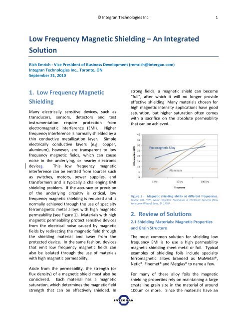
© Integran Technologies Inc. 1<strong>Low</strong> <strong>Frequency</strong> <strong>Magnetic</strong> <strong>Shielding</strong> – An IntegratedSolutionRich Emrich ‐ Vice President of Business Development (remrich@intergan.com)Integran Technologies Inc., Toronto, ONSeptember 21, 20101. <strong>Low</strong> <strong>Frequency</strong> <strong>Magnetic</strong><strong>Shielding</strong>Many electrically sensitive devices, such astransducers, sensors, detectors and testinstrumentation require protection fromelectromagnetic interference (EMI). Higherfrequency interference is normally shielded by athin conductive metallization layer. Simpleelectrically conductive layers (e.g. copper,aluminum), however, are transparent to lowfrequency magnetic fields, which can causenoise in the underlying, or nearby electronicdevices. This low frequency magneticinterference can be emitted from sources suchas switches, motors, power supplies, andtransformers and is typically a challenging EMIshielding problem. If the accuracy or precisionof the underlying circuitry is critical, lowfrequency magnetic shielding is required and isnormally achieved through the use of specialtyferromagnetic metal alloys with high magneticpermeability (see Figure 1). Materials with highmagnetic permeability protect sensitive devicesfrom the electrical noise caused by magneticfields by redirecting the magnetic field throughthe shielding material and away from theprotected device. In the same fashion, devicesthat emit low frequency magnetic fields canalso be isolated through the use of materialswith high magnetic permeability.Aside from the permeability, the strength (orflux density) of a magnetic shield must also beconsidered. Each material has a magneticsaturation, which determines the magnetic fieldstrength that can be effectively shielded. Instrong fields, a magnetic shield can become“full”, after which it will no longer provideeffective shielding. Many materials chosen forhigh magnetic intensity applications have goodsaturation, but higher saturation often comeswith a sacrifice on the absolute permeabilitythat can be achieved.Figure 1 ‐ <strong>Magnetic</strong> shielding ability at different frequencies.Source: Ott, H.W., Noise reduction Techniques in Electronic Systems (NewYork: John Wiley & Sons, © 1976)2. Review of Solutions2.1 <strong>Shielding</strong> Materials: <strong>Magnetic</strong> Propertiesand Grain StructureThe most common solution for shielding lowfrequency EMI is to use a high permeabilitymagnetic shielding sheet metal or foil. Typicalexamples of shielding foils include specialtyferromagnetic alloys branded as MuMetal®,Netic®, Finemet® and Metglas® to name a few.For many of these alloy foils the magneticshielding properties rely on maintaining a largecrystalline grain size in the material of around100µm or more. Since the materials have an
© Integran Technologies Inc. 2equilibrium state grain size of around 1‐10µm,the large grain structure must be achievedthrough annealing the metal at hightemperatures, often in a tightly controlledatmosphere to control impurities.Other foils have an amorphous (i.e. nocrystalline grains) or nanocrystalline structurewhich is normally achieved through complexmanufacturing techniques including rapidsolidification and high frequency annealingprocesses.2.2 Existing <strong>Shielding</strong> SolutionsAlthough specialty foils are very effective EMIshields, they are best suited to shielding simplyshaped parts. There are currently a fewmethods for creating parts with relativelycomplex geometries, described in Figure 2 andFigure 3.Figure 2 ‐ Existing <strong>Shielding</strong> Solutions (Part 1).Figure 3 ‐ Existing <strong>Shielding</strong> Solutions (Part 2).2.3 Foil Lay‐up and Formed FoilsSince sheet metal or foils are manufactured flat,materials that resist forming operations, likeglassy amorphous alloys, must be cut to shapeand laid onto flat surfaces in order to achievethe necessary part shielding. Although thesematerials have excellent shielding performance,this lay‐up approach is a cumbersome methodfor shielding parts with any contour or shape.Other less brittle shielding materials can also becut and formed to the shape required. Forexample, a sensitive transducer measuring afaint analog current might require a “can” ofmaterial to be formed to integrate into theenclosure or circuit board for the device. Thisshape would need to be cut and stamped fromthe original sheet metal or foil supply. Althoughthis process adds cost to the shield, it is not, initself, a particularly challenging operation.Unfortunately, the forming operation reducesthe effectiveness of the shield by introducingdeformation into the material – destroying thekey material characteristic that generates thehigh permeability. To restore the defect‐freestructure, the material must be annealed oncemore in the high temperature controlledenvironment to restore shielding effectiveness.
© Integran Technologies Inc. 3This presents a restriction for customers as theforming operation now has to be coupled withan annealing operation, limiting the possiblemanufacturers, or adding an additional step inthe supply chain.Moving away from shielding efficacy, theforming step also sets a practical size limit ascomplex or small geometries are difficult toproduce. As electronic structures andpackaging shrinks, discrete, formed shields maynot be the optimal solution. Lastly, once thediscrete shield is cut, formed, and annealed, itstill needs to be integrated into the assembly ofthe shielded part. This integration requireslabor and often relies on adhesives, furtheradding to the assembly part count, andcomplicating the assembly cost and complexity.2.4 Metal Injection MoldingFine specialty ferromagnetic powders can nowbe injection molded with a binder to createcomplex parts that are effective low frequencymagnetic shields. After molding, the parts arethermally or chemically treated and thensintered at high temperatures where the binderis removed. Secondary operations aresometimes required to achieve the final shape.Although this process can make effectiveshields in relatively complex forms, partshrinkage must be accounted for, as well asmechanical considerations such as part porosity(2%) and brittleness. As tooling costs can behigh, this method is ultimately best suited forhigh volume but relatively small parts.applications where weight is critical, steel isoften being replaced by other materials such aspolymers or aluminum which have little or nolow frequency shielding capability. Thesematerials must often be combined with one ofthe other aforementioned solutions or thedirect part coating solution discussed in thenext section.3. Alternative solution: directCoating of parts withNanovate EMAn alternative solution is to apply a highmagnetic permeability Nanovate EM coatingdirectly to the surface of a part, as shown inFigure 4. This process is more easily adapted tosmall and complex shield shapes and avoidsmany of the possible drawbacks of a discreteshield, including eliminating annealing steps.2.5 Metal ComponentsFinally, conventional metal components canalso be used for low‐frequency EMI shieldingsuch as steel stampings. For many applications,this can be a very cost effective method but theweight addition can be problematic in someapplications. Much thicker steel stock will berequired to achieve the same shieldingeffectiveness as specialty ferromagnetic alloysand in many cases a minimum thickness of steelis required for the forming operations. In manyFigure 4 ‐ Part coated with a Nanovate EM coating.Coating parts with conductive surfaces hasoften been used for high frequency EMIshielding in electronics applications usingtechniques such as PVD, conductive paints, andelectroless and electrolytic plating. In these
© Integran Technologies Inc. 4cases, the primary requirement is a thinconductive coating. With the recentintroduction of high magnetic permeabilityNanovate coatings, the same concept can nowbe used for low frequency magnetic shielding.3.1 <strong>Magnetic</strong> Properties OF Nanovate EMCoatingsIn contrast to conventional shielding materialswhich derive magnetic properties from theirlarge, un‐deformed grain structure, NanovateEM coatings derive their magnetic propertiesfrom their very small (nanometer, in fact) grainstructure. Similar to large grained shieldingmaterials, Nanovate EM coatings can achievehigh permeability, and therefore similarmagnetic shielding performance. The graphshown in Error! Reference source not found.illustrates the relationship between coercivityand grain size for ferromagnetic materials. Thegraph shows that coercivity is at a minimumwhen grain size is reduced to the nanometerscale or increased to the micron scale.Typically, magnetic shielding materials with lowcoercivity also possess high permeability, and,in turn, exhibit good low frequency magneticshielding characteristics.benefit lies in their processing and designflexibility. These materials are used mostfrequently as a coating directly onto partsubstrates such as metals (e.g. aluminumenclosures), polymers (e.g. thermoplasticformed parts) and composites (e.g. carbon fibercomposite structures), which avoids anyforming operations. The coating can beintegrated directly into the part packaging orenclosure, which reduces part count byeliminating the discrete formed shield andrelated adhesives and labor. Selective coating ispossible, allowing shielding performance thatcan be delivered where it is needed most andavoiding unnecessary added weight. Forinjection molded polymers in particular,monolithic part integration is now possiblewhere the shielding function can be moldeddirectly into the larger electronics enclosure orpart packaging.Figure 6 ‐ Aluminum housing coated with nanocrystallineferromagnetic coating. Source: Integran Technologies Inc.Figure 5 ‐ Trend of coercivity vs. grain size. Source: Adapted from G.Herzer, Mat. Sci. Eng., A133 (1991).3.2 Processing and Design Benefits andlimitations of Nanovate EMWhile the magnetic shielding characteristics ofNanovate EM coatings are good, their realAside from avoiding the forming operation,deformation Nanovate EM coatings does notaffect their grain size and therefore retains theshielding effectiveness, avoiding both a loss inperformance and a re‐annealing step. On theother hand, the long term operatingtemperature must be kept under a threshold of
© Integran Technologies Inc. 5approximately 400°F (varies, depending on alloycomposition) to avoid grain growth back to alarger crystalline equilibrium state. As with anysolution this approach has its own drawbacks.The metal coating operation is a secondaryoperation which adds cost to the part. Inaddition, the thickness and distribution of metalin a typical deposition process fornanocrystalline metals is influenced by partgeometry. Despite these factors, theapplication process is industrially scalable, andthe metal coating approach is effective wherediscrete shields are awkward or impractical.The part also benefitted from increased surfacehardness, and an aesthetically pleasing finish.Polymer parts can also benefit greatly fromdirect coating with Nanovate EM. Complexmoldings can be coated to provide additionalstiffness, strength and surface hardness inaddition to magnetic shielding, thereby tocreating multifunctional parts. Thesemetal/polymer hybrid parts can be lighter andthinner than their fully metal die‐castcounterparts. Error! Reference source notfound.Figure 7 depicts a cell phone housingcoated with Nanovate EM, adding stiffnessand strength to the polymer part. Figure 8shows a similar polymer housing with thecoating applied selectively. This deliversshielding performance where it’s required,eliminating unnecessary weight. Using aselective coating process can enable monolithicintegration of discrete parts in an assembly,reducing part cost.Figure 7 ‐ Polymeric cell phone components coated withnanocrystalline Nanovate shielding. Source: IntegranTechnologies Inc.An example of a metal part which can benefitfrom direct part coating is shown in Figure 6which depicts a complex aluminum machinedhousing that required shielding. The applicationis weight sensitive and required layups of mumetalfoils in most areas and labor intensivework to bend the foils and bond them to shieldthe corners. As an alternative, 50 microns thickNanovate EM coating was applied by IntegranTechnologies. The part has performed well ininitial EMI testing and the majority of the foilscould be eliminated, saving weight and cost.Figure 8 ‐ Polymeric cell phone component selectively coatedwith nanocrystalline Nanovate shielding. Source: IntegranTechnologies Inc.3.3 Material Property Benefits of NanovateEMAnother useful property of nanocrystallineNanovate EM coatings is that they have ahigher strength and hardness than their coarsegrainedcounterpart materials. When appliedto polymer substrates, this higher strength canbe used to dramatically increase the strengthand stiffness of the hybrid part. A relatively
© Integran Technologies Inc. 6weak or flexible polymer enclosure can nowbecome a rigid structural part with gooddurability. The high yield strength and goodductility also make the coating particularly wellsuited for polymer and composite applicationswhich experience a lot of flexing. In bending orflexing applications, lower strength coatingswould plastically deform, and traditional highstrength coatings, which are normally brittle,would crack and fail at low loads. Examples ofthe improvement in mechanical properties ofNanovate EM with respect to conventionalmagnetic shielding foils are shown in Figure 9and Figure 10.Figure 9 ‐ Improved Yield Strength. Source: IntegranTechnologies Inc.Nanocrystalline metals can now be made fullydense, meaning they have no voids or porosity.Having a highly impermeable coating could bebeneficial either for keeping liquids or gasesfrom penetrating the surface of a part, as wouldbe the case for protecting a polymer case fromchemical attack, or from keeping the part fromoutgassing into the environment. This may be asecondary consideration in semiconductor orspace applications.4. SummaryIn summary, while specialty ferromagnetic foilsand sheet metal stock are useful for creatingrelatively simple geometry discrete magneticshields, they require forming, annealing, andassembly steps and are not amenable to smallor complex parts. Metal injection molding andstandard steel parts can also solve manyshielding problems but run into challenges inweight and lower shielding effectiveness.Nanocrystalline ferro‐magnetic metal coatings,such as Nanovate EM offer an alternativesolution for directly shielding metal, polymer, orcomposite parts which can reduce cost bysimplifying the supply chain and assemblyprocess. This metal coating process also opensthe door to small or complex shields whichwere previously impractical with discreteshields. Additional benefits can also be realizedby using the superior mechanical properties ofnanocrystalline metals to strengthen, stiffen,render impermeable, or add durability to apolymeric part. A summary of characteristics ofNanovate EM, and conventional shielding foilis shown in Figure 11.Figure 11 ‐ Summary of Characteristics of Nanovate EM, andConventional <strong>Shielding</strong> Foil.About Integran TechnologiesInc.Figure 10 ‐ Improved Hardness. Source: Integran TechnologiesInc.Integran Technologies Inc. is a world leader inthe development and commercialization ofadvanced nanocrystalline metal coatings and
© Integran Technologies Inc. 7other metallurgical nano‐technologies.Integran’s affiliated companies include:Powermetal Technologies (Carlsbad, CA) whichdevelops and manufactures products for thesports equipment and consumer productsectors; and Integran TechnologiesUSA (Pittsburgh, PA) which is focused oncommercialization of Integran’s technologies inthe United States.Webwww.integran.com


![[ thursday ] morning sessions 8:30 am-noon - Interference Technology](https://img.yumpu.com/23176841/1/190x247/-thursday-morning-sessions-830-am-noon-interference-technology.jpg?quality=85)

